New features

2023.b Version

19 July 2022
Index

New features common to several programs

Applications with a 3D environment

New options bar for entering elements on the workspace

Since version 2020.f, applications with a 3D working environment include a floating toolbar to make it easier to enter or edit model components on the workspace. The options displayed in this toolbar depend on the active view and the element(s) being entered or edited.

This component is now anchored below the application toolbar. This makes better use of the available space in the user interface.

Managing the visibility and object snaps of external elements

In the previous version (2023.a), a tool was implemented in the user interface of some of the programs with a 3D working environment. This tool allows elements from the building's digital model, originating from the associated BIMserver.center project, to be managed from the "Elements read" menu located in the left-hand sidebar of each application. More information is available in the new feature for version 2023.a "Managing the visibility and object snaps of external elements".

In the current version (2023.b) this management of visibility and object snaps is also implemented in:

  • CYPEHVAC Ductwork
  • CYPELEC Distribution (program featuring the 3D working environment from version 2023.b onwards).

Programs included in the Open BIM Workflow

"Export BIM model" option in the connection between applications

As of version 2023.b, Open BIM applications that have a direct link to other tools include the "Export BIM model" option. This option, which is active by default, allows users to decide whether to export the job information produced from the source application before opening the target application.

The possibility to skip the export process saves a significant amount of time when continuing the workflow in several different programs without making changes to the source application. However, it is important to note that if this option is deactivated and changes have been made, they will not be shared in the BIMserver.center project.

Implementing codes and improving their enforcement

Concrete structures

Implementation. PN-EN 1992-1-1:2008/NA:2016-11 (Poland)

Polish National Annex to Eurocode 2 (Design of concrete structures. Part 1-1: General rules and rules for buildings).

Implemented in CYPECAD, CYPE 3D, Reinforced concrete cantilever walls and Embedded retaining walls, for the analysis and design of concrete structures.

CYPE Architecture

Measure angles

The "Measure angles" tool has been added to the "Sketch", "Architecture" and "Furniture" tabs. With this tool, users can measure an angle in the space by marking three points.

Create a level at the elevation of a point

The "Create a level at the elevation of a point" tool has been implemented. It can be found among the tools that appear when the "Levels" option is opened in the "Architecture" tab of the top menu. With this feature, a new level can be created at the elevation of a point by selecting it in the view of the user's choice.

New features and improvements in the "Furniture" tab

In version 2023.b of CYPE Architecture, several new features and improvements have been implemented in the "Furniture" tab:

  • New furniture
    New furniture has been included in the beds, sofas, extractor fans, sinks and vegetation sections.

  • Adjustment in the positioning of shelves, worktops, cupboards and counters
    This setting allows the element to be drawn either centred, to the right or to the left of the entry line.

  • Anchor point for furniture
    This tool allows any piece of furniture to be rotated simply and manually, i.e. it is not necessary to enter a numerical angle as in previous versions. If, when entering a piece of furniture, the anchor point is used to give it a new orientation, the following pieces of furniture will be entered with the rotation indicated in the first piece of furniture.

  • Automatically orienting furniture with respect to walls
    Furniture is automatically oriented during the entry process when the cursor detects a wall, thus making it easier to position furniture correctly. In previous versions, furniture orientation had to be carried out manually.

  • Furniture symmetry tool
    This tool allows users to enter symmetrical furniture with respect to other furniture that has already been entered. This tool improves furniture entry, especially in the case of showers, which had some limitations in previous versions.

  • Opening for a sink in the worktop
    When a sink is placed on a worktop, the worktop's surface is detected and an opening is created in the worktop, placing the sink in the correct position.

  • Editing furniture
    General improvements have been implemented for snapping and editing furniture elements, including tools for measuring areas and angles.

  • "Layer", "Level", and "Group" information for furniture elements

  • Entering furniture using floating windows
    Floating windows allow faster element entry as they do not need to be accepted. Users can easily change one piece of furniture for another of the same type and see it immediately updated on screen.

Open BIM Construction Systems

Exterior floor slabs

In previous versions of the application, after being linked to the BIMserver.center project, all exterior exposed floor slabs entered in the architectural model were added to the "Roofs" group. As of version 2023.b, CYPE Construction Systems includes the "Exterior floor slabs" category in the "Building envelope" section. This group includes the floor slabs that are exposed to the exterior and that have not been defined as roofs. This new category is incorporated into the documents generated by the program and is exported when the model is shared in the BIMserver.center project.

Thermal and acoustic simulation applications will now interpret these construction systems as floor slabs instead of roofs.

Open BIM Analytical Model

Tool for combining spaces

The "Group spaces" tool has been added to the list of spaces in the analytical model and is available via the "BIM Model" button on the toolbar. By running it, users can choose several spaces and the application will group them into a single space, which will contain all the surfaces and edges of the selected spaces. Furthermore, the surface area and volume values of the new space will be calculated.

This tool is particularly useful for spaces that are entered independently in the architectural model but are connected and, therefore, form a single analytical space.

Other improvements and corrections

Open BIM Analytical Model version 2023.b includes the following improvements and corrections of the program for certain cases:

  • Deselecting an adjacent surface
    Adjacent surfaces can now be deselected in the configuration panel of an analytical model surface adjacent to "Surface".

  • Checking adjacent surfaces
    In previous versions, the "The adjacent surface is not defined" check was treated as an error message, it is now a warning.

  • Check for elements of the physical model
    The "No analytical surface has been defined for an element of the physical model" is now unchecked by default.

  • Opening detection
    Opening detection in the automatic analytical model generation process has been improved.

  • "External environment" type spaces
    A problem that could cause warnings on external analytical surfaces due to the "A valid volume must be defined for the space" volume check being carried out in "External environment" type spaces has been corrected.

  • Joining surfaces
    An error that could occur when using the "Join surfaces" tool with more than two surfaces of the analytical model has been corrected.

  • Generating an opening on an analytical surface
    An error that could occur when using the "Generate an opening in an analytical surface based on an opening of the physical model" tool has been fixed.

CYPECAD

Editing deflection groups in beam frames

In version 2023.b, three options have been added for editing the deflection groups of beam frames. Up to this version, deflection groups were generated automatically and no changes could be made. These options are as follows:

  • Automatic
    Allows users to automatically generate the deflection groups.

  • Edit
    Allows users to modify the "Support conditions" and deflection type for each deflection group.

  • Join / Divide
    Allows users to join and divide deflection groups. When selecting a node between two deflection groups, those groups will be joined together. Selecting a node inside a deflection group will split that group.

Exporting enough data on structural elements with steel sections to the BIM model in order to allow their quantities to be generated

As of version 2023.b, CYPECAD exports the quantities of the IFC standard ("IfcQuantitySet") related to structural elements with steel sections to the BIMserver.center project. These quantities can be read by other applications integrated in the Open BIM workflow via the BIMserver.center platform.

For example, the Open BIM Quantities tool can use this information for generating the bill of quantities.

"Parapet" type construction elements

In previous versions, the construction elements that could be entered in CYPECAD were defined between groups ("Beam definition" tab > "Loads" menu). Now the possibility to enter "Parapets" has been implemented. Parapets are defined in the same way as the construction elements between groups, but instead of specifying the end group, the height of the parapet must be defined.

Parapets will not be included in seismic analyses, as opposed to partitions.

When importing a BIM project, elements whose "IfcWallTypeEnum" property is "PARAPET" shall be automatically marked to be imported as construction elements of the "Parapet" type. If they do not have this property, they can be marked manually in order to be generated correctly.

“Sections” submenu

The interface of this submenu has been updated. It consists of the following options:

  • Enter dimension lines
  • Introduce sections (Sections at cut line)
  • Introduce sections (Outside the drawing)
  • Modify
  • Delete

Consideration of transverse reinforcement when calculating the shear resistance in beams

The "Shear resistance calculation" option has been implemented in order to optimise the check and design of the transverse reinforcement of beams. It can be accessed from the "General data" panel (General data > Bars > By position > Beam options > Design / Code checks). 

If this option is activated, the calculation of the shear resistance in beams will always be carried out considering the contribution of the transverse reinforcement and the additional provisions according to the criteria of the code for this type of reinforcement will be taken into account. Otherwise, a check is first made as to whether the element resists the shear resistance without considering the transverse reinforcement.

Other improvements and corrections

CYPECAD version 2023.b includes other minor improvements and corrections of the program for certain cases:

  • Exporting reinforcement bars of beam frame openings to the BIM model

  • Beam reinforcement editor
    The editing of reinforcement bars has been improved so that when the value of the total length is changed, it is modified proportionally on both sides of the bar (if it is a negative moment rebar with respect to the node, and if it is positive moment rebar with respect to its centre).

  • Beam intersection references
    The generation of beam intersection references has been improved when a base reference is defined with more than 5 characters.

  • Exporting to the BIM project
    The size of the exported data has been considerably reduced in order to view the reinforcement of all elements in a BIM project.

  • Transverse reinforcement in the form of column and beam stirrups
    The generation of transverse reinforcement in the form of column and beam stirrups has been improved in accordance with the "Eurocode 8" seismic code. Stirrup anchorage is now carried out with 10ø, while previously it was carried out with 5ø.

  • Improving the import of walls from a BIM project
    In some cases, a wall could not be entered if there was an intersection where the end of one wall was not positioned on the axis of the other wall.

  • Joist floor slab cover
    The joist floor slab cover range has been increased to 8 cm.

  • Fire resistance check
    An error that occurred in jobs that included frames with locked reinforcement and an active fire resistance check has been fixed. After carrying out the analysis, the fire resistance check of frames with locked reinforcement could not be consulted. Now the error no longer appears, although, in jobs where this problem occurs, the frames must be unlocked and reanalysed in order to be able to consult these checks. These checks can also be accessed again if the frame reinforcement is edited and a modification is made.

  • Reports
    An error that occurred when generating a customised report that included the "Beam reinforcement report" and "U.L.S. Checks - Beams" chapters has been fixed.

  • Editing frame reinforcement
    An error that occurred when editing beam frame reinforcement after joining groups has been fixed.

StruBIM Embedded Walls / StruBIM Deep Beams / StruBIM Rebar

Exporting bars from the StruBIM Embedded Walls and StruBIM Deep Beams programs to the BIM model

The StruBIM Embedded Walls and StruBIM Deep Beams programs export the reinforcement of the structural elements they consider to the BIM model. They can now be imported by the StruBIM Rebar program to produce the joint BIM model of the reinforcement from these and other programs.

The programs that currently export bars corresponding to the reinforcement are the following:

  • CYPECAD
  • StruBIM Shear Walls
  • StruBIM Embedded Walls
  • StruBIM Deep Beams

CYPE Connect / StruBIM Steel

Checking anchors

Version 2023.b implements the detailed checking of anchors in accordance with Eurocode EN 1992. Until version 2023.b, the analysis of the connection was carried out by considering the anchors positioned and the non-linear contact between steel and concrete, but without checking the resistance of the anchors.

These new detailed checks can be consulted in the "Analysis" tab, as well as the checks already implemented for the rest of the elements. These checks can be for a single anchor as well as for the group.

In the project options, in the "Codes" dialogue box, the group of options relating to the concrete code for anchor testing has been implemented.

The "Anchors" operation includes the "Check anchors" option. When this option is activated, the program checks the anchors and also allows certain parameters and factors that must be taken into account in this check to be edited.

The connection summary list includes the resistance tables of the anchor group and the individual resistance of each anchor.

Quick access to operations from the 3D view

Up until version 2023.b, the operations entered in the connection were accessed via the side list. In this version, quick access has also been provided by clicking on elements in the 3D view. Selecting elements in the 3D view will open the operation where the element is defined in the left panel.

CYPELEC Electrical Mechanisms

Automatic saving options

CYPELEC Electrical Mechanisms version 2023.b now includes the possibility of automatically saving jobs every so often.

New example job

A new example job has been added for an apartment block with 8 dwellings. In this building, based on the architectural model, the distribution of electrical mechanisms and lighting points is completed with the corresponding checks of the protection volumes in bathrooms and toilets, and the minimum provision in rooms.

CYPELEC Distribution

New 3D work environment

CYPELEC Distribution has changed from a 2D environment to a new 3D work environment, achieving greater capacity in the design and modelling of the electrical installation.

The new 3D work environment achieves the following:

  • Greater geometrical accuracy when placing receivers and nodes that belong to the feeders.
  • Improved distribution of the conduits through which the supply circuits and lines to the receivers run, including the vertical utilities shafts between floors.

The implementation of the 3D work environment, together with other new features presented in this patch, prevents this version 2023.b of the program, and any subsequent versions that are published, from reading any jobs created using versions prior to 2023.b. Nevertheless, should users wish to read jobs from previous versions via CYPELEC Distribution, they should note that this can always be carried out with a version prior to version 2023.b. Thus, using this earlier version, users can edit, modify or simply view jobs from previous versions. Furthermore, previous versions of the program can be downloaded and installed at BIMserver.center should users wish to install them.

For new jobs, we recommend that this latest version is always used.

Importing equipment from the BIM model

CYPELEC Distribution allows lights contained in the BIM project to be imported from lighting design programs such as CYPELUX. This extends the number of programs containing electrical equipment that can be imported into CYPELEC Distribution. Currently, these programs are as follows:

  • CYPELUX
  • Open BIM DAIKIN
  • Open BIM BOSCH
  • Open BIM PANASONIC

The loads and equipment imported from the BIM model can be quickly converted into receivers by using an icon on the toolbar called "Assign receivers". The table displayed in the image lists the different loads and electrical equipment imported along with their power consumption so that a receiver with the necessary electrical features can be assigned to each one of them.

Receiver library

The receiver library has been added to speed up the introduction of receivers with electrical load characteristics of the same type. This tool is located in "General options" > "Types of receivers". In the receiver editing panel, the following must be indicated:

  • Reference.
  • Type of load involved (lighting, emergency, electrical outlet, motor, lifting device, generic).
  • Electrical features.
  • Customised symbols if required.

Improved assignment of lines and circuits inside the conduits

The conduit editing panel has been modified to allow feeders to be defined. The upper part of the panel shows the supply lines to switchboards or link nodes, and the lower part shows the circuits belonging to the switchboards.

The automatic generation of lines and circuits inside the conduits is also improved. This tool is represented by an icon on the toolbar called "Generate conductors".

Improved tool for generating branches

Due to the change from the 2D to the 3D work environment of the program, the "Generate branches" tool has been modified. Help on how to use it has now been included, indicating the steps to be followed:

  1. Selecting the nodes to which the conduits are to be placed.
  2. Selecting the node from which the conduits are to be placed.  
  3. Selecting the level at which the horizontal conduits are to be entered.

This generation of branches can be carried out either from junction boxes to receivers, pattress boxes or other junction boxes, or from switchboards to junction boxes.

New example jobs

Two examples have been added for an electrical workshop which has opted for an interior installation and an example of an apartment building with 8 dwellings in which, apart from the interior installation, it also distributes the feeders.

CYPELEC Core

Import and checking of the specifications from the CYPELEC Distribution program

Should the BIM project contain electrical distribution information provided by the CYPELEC Distribution program, this information will be processed by CYPELEC CORE so that this program shows the electrical project specifications to be met in the left-hand margin of the work area.

Compliance with these project requirements is based on the verification of the following points:

  • The connection hierarchy of the wiring diagram must be followed so that all lines and circuits are defined and connected according to the imported diagram.

  • The requirements must be met for each of the lines and circuits. As a result, there are three possible scenarios:
    • The measuring length must be met for lines belonging to feeders and supply lines to switchboards or sub-switchboards.
    • If a circuit belongs to a switchboard and a circuit with a concentrated load is chosen, the total active power demand of the circuit and the measuring length must be met.
    • If a circuit belongs to a switchboard and a circuit with distributed load is chosen, the definition and distribution of each of the loads along the supply circuit must be met, in addition to the active power demand and measurement length, and the electrical properties of each of the loads must be met for each of them.

It is worth mentioning that in order to meet the requirement of the measurement length of a circuit, the sum of the design length plus the sum of the additional length must be equal to or greater than the required length. Both lengths are present in the edit panel of a circuit as shown in the following image.

CYPEPLUMBING Water Systems

New features in label management

The use of project labels has been improved. For this purpose, the following features have been added:

  • Element identification
    The item corresponding to the label is highlighted when the label is selected.

  • Move label in 2D mode
    This tool allows users to move the element labels in the installation in the XY plane.

  • Move label in 3D mode
    Allows users to move the element labels in the installation in the XYZ plane.

  • Move label to initial point
    Allows the initial position of the label to be restored after it has been moved.

Open BIM Quantities

Name of IFC entities

As of version 2023.b, in the BIM project component tree of the "Quantities of the BIM model" tab, a translated text can appear next to the IFC entities. This makes it easier for users to identify the codes used in the standard IFC format for the most common entities.

Selecting the active set of measurement rules

A button has been added to the "Sets of measurement rules" list components that are available from the toolbar of the "Quantities of the BIM model" tab. In previous versions, the active set of measurement rules was the one selected in the list. Now, via this button, users can explicitly indicate the active set of measurement rules in the project.

BIM model layers

As of version 2023.b, Open BIM Quantities offers three different ways of displaying the BIM model component tree in the "Quantities of the BIM model" tab. Up until now, the elements could be arranged according to the IFC entity to which they belong (IfcWall, IfcSlab, IfcSpace, etc.) or the spatial structure (IfcSite->IfcBuilding-> IfcBuildingStorey, etc.). In this update, the "Layers" button has been added to the "View" group of options in the application toolbar. By clicking on it, the tree is organised according to the layers defined in the IFC model. In this case, the layer components are grouped together in a tree branch being assigned the name of that layer.

New "Assign all" option in the sets of measurement rules

The "Assign all" option has been added in the "Assign codes" panel of a cost database in a set of measurement rules. With this tool, items used in the rules of measurement can be updated. If there is an item in the cost database with the same code as in a rule, the latter will be updated with the database's properties (work section, code, unit and reference). When the process is complete, a summary is displayed with the codes of the items that have been updated.

New structure of the "Quantities" panel in the "Quantities of the BIM model" tab

The "Quantities" panel has been improved. The following elements are now included in its structure:

  • A main branch has been added which contains all the elements and also indicates the position of the IFC model in the component tree.
  • Items' quantity detail lines can now be expanded and collapsed.
  • The quantity of each item is now calculated.
  • The tags of an item's detail lines can now be displayed.
  • The partial and accumulated subtotal lines defined according to the procedure described in the new feature "Subtotal line management from the set of measurement rules" have been added.

Subtotal line management from the set of measurement rules

As of version 2023.b, Open BIM Quantities allows the subtotals in the quantity detail lines to be generated from the sets of measurement rules. To do this, the tags associated with the rules of measurement are used. 

Now, in the "Tags" window that appears in the editing panel of an item, the "Generation of subtotals" option is included. From this field, users can choose whether to generate partial or accumulated subtotals. These subtotals are linked to the first tag entered in the list and a subtotal line will be created in the quantity details each time the value changes. For this reason, at least one tag must be entered in the item to be able to generate subtotals from a rule of measurement.

Updated example jobs

The French example job "Immeuble de bureaux" has been added along with its cost database and set of measurement rules ("Français - Immeuble de bureaux").

The Spanish example job "Unifamiliar aislada" has been updated along with its cost database ("España - Unifamiliar aislada").

Open BIM Quantities / Applications with a "Bill of quantities" tab

Selecting the active cost database

A button has been added to the "Cost databases" list components, available from the toolbar in the "Bill of quantities" tab. In previous versions, the active cost database was the one selected in the list. Now, using this button, users can explicitly indicate the active cost database in the project.

Applications with a "Bill of quantities" tab

"Sort" tool

The "Sort tree" option has been added to the "Edit" group of the toolbar in the "Bill of quantities" tab. The option is also available in the "Project database" and "Cost databases" editing windows. This feature allows users to sort the work sections and/or items by their code and in alphabetical order.

Visible columns

Due to the increase of available options, the way to activate or deactivate the visibility of the columns in the bill of quantities table or in the databases has been modified. For this purpose, the "Columns" button has been added in the "View" group of the toolbar in the "Bill of quantities" tab, as well as in the editing windows of the "Project database" and the "Cost databases". Clicking on it displays a panel where the visible columns, which are sorted by category, can be selected.

Along with those available in previous versions, the following columns have been added:

  • General parameters
    • ABCD

  • Valuations
    • PartVal(%)
    • PartValuatQuant
    • PartValAmnt
    • OrigVal(%)
    • OrigValuatQuant
    • OrigValAmnt

Using the description instead of the summary for concepts in reports

The "Show the complete description instead of the summarised description" option has been added in the "BoQ Reports" configuration panel. When this option is checked, the text entered in the "Description" tab of its definition in the "Project database" is used as a reference for the items. Otherwise, the text entered in the "Summary" field is used.

Job certifications

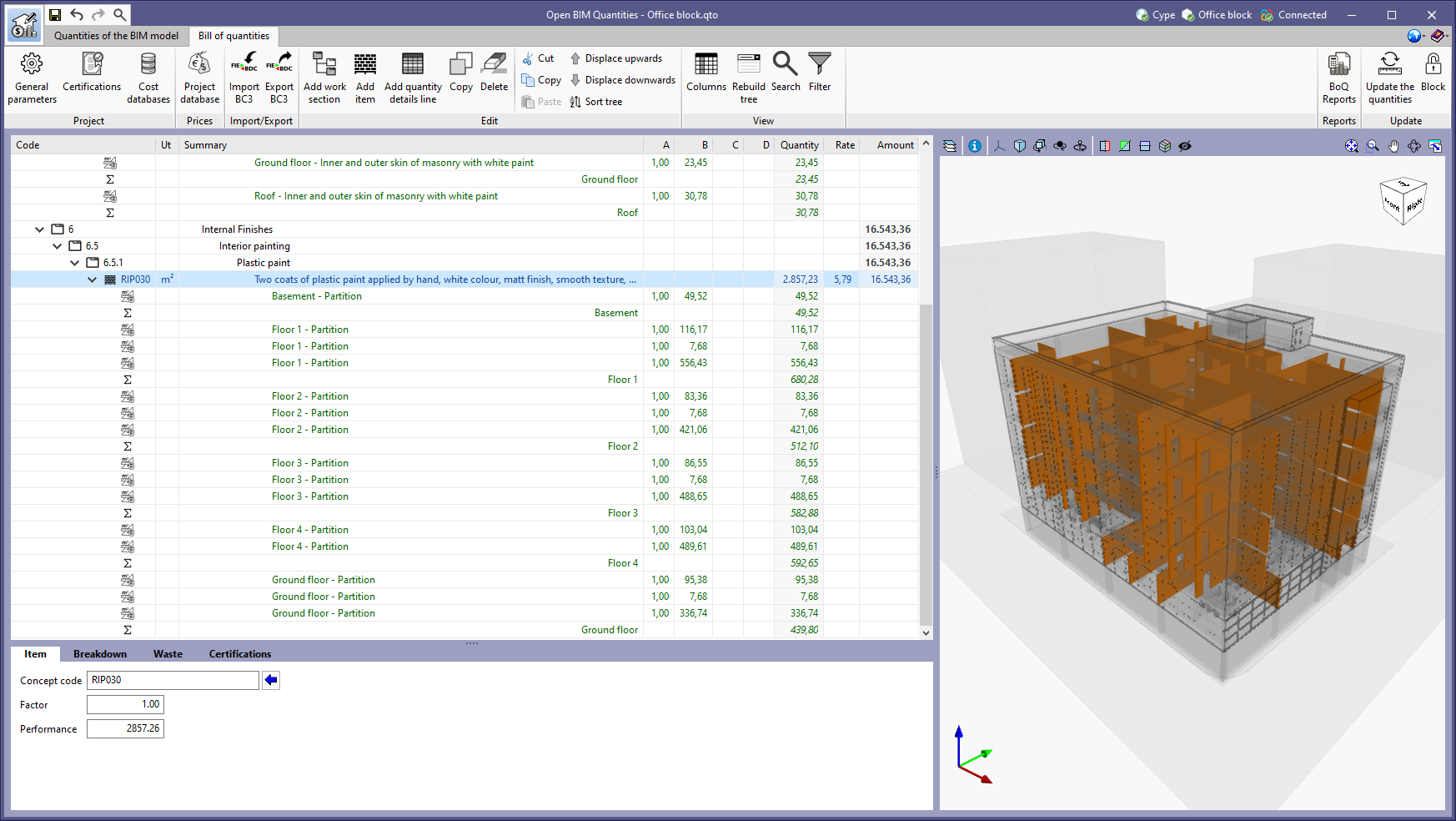
As of version 2023.b, job certifications can be registered and managed from the "Bill of quantities" tab. A job certification consists of economically quantifying the job carried out up to a given moment in accordance with the items included in the bill of quantities that has been accepted and signed between both parties.

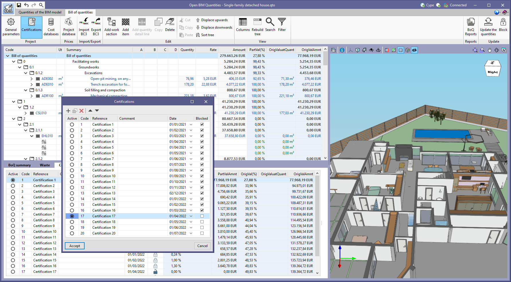
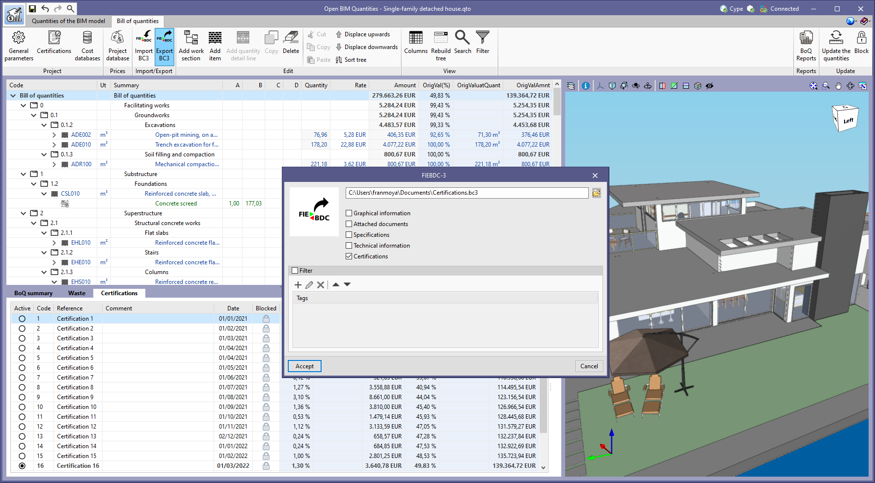
To define the job certifications, the "Certifications" button has been added to the "Project" group in the toolbar. A job certification has the following user-configurable parameters:

  • Active
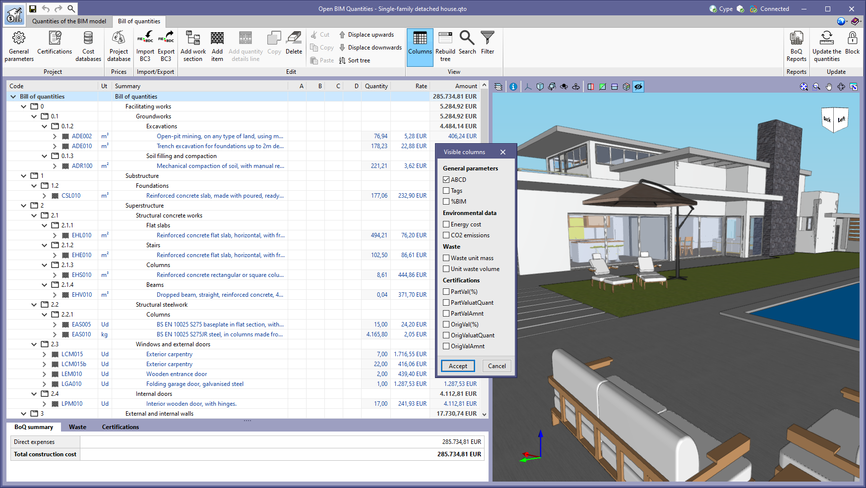
    Indicates which certification is active in the list. The columns of the "Certifications" group (see the "Visible columns" new feature included in the 2023.b new features for applications with a bill of quantities tab) shall refer to the active certification.
  • Code
    Sets a unique identifier for the certification.
  • Reference
    The certification reference. It will be displayed in the documents generated by the application.
  • Comment
  • Date
    The date on which the certification is to be submitted.
  • Blocked
    Allows the certification to be locked to avoid it being editable from the bill of quantities table.

Once the job certifications have been defined, the quantities can be valued from the new "Certifications" tab found in the editing panel of a bill of quantities concept. The way in which the executed quantity is indicated depends on the type of item:

  • Items without breakdown
    The quantity is entered from the "Certifications" tab of the item.
  • Items with breakdown
    The quantity is entered from the "Certifications" tab of the quantity detail lines.

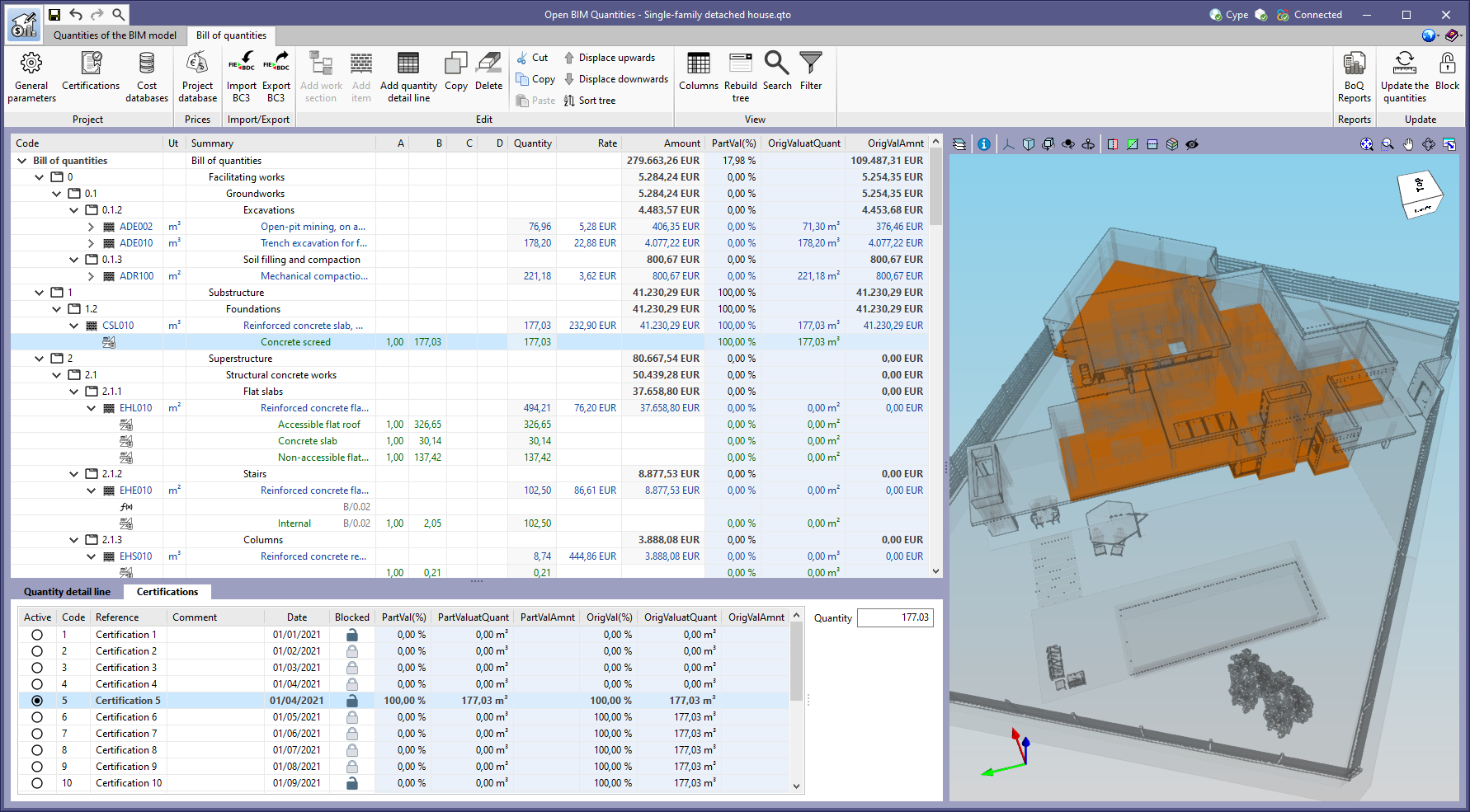
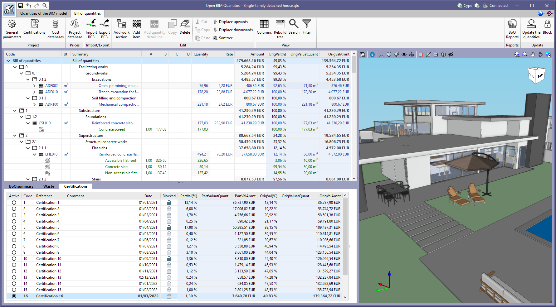
The "Certifications" tab can also be used to consult the results of the job certifications in a work section or in the complete bill of quantities. This panel displays a list that, in addition to the general data of each certification, includes the following columns:

  • PartVal(%)
    Partial valuation percentage
  • PartValuatQuant
    Partial valuation quantity
  • PartValAmnt
    Partial valuation amount
  • OrigVal(%)
    Percentage valued at origin
  • OrigValuatQuant
    Quantity valued at origin
  • OrigValAmnt
    Amount valued at origin

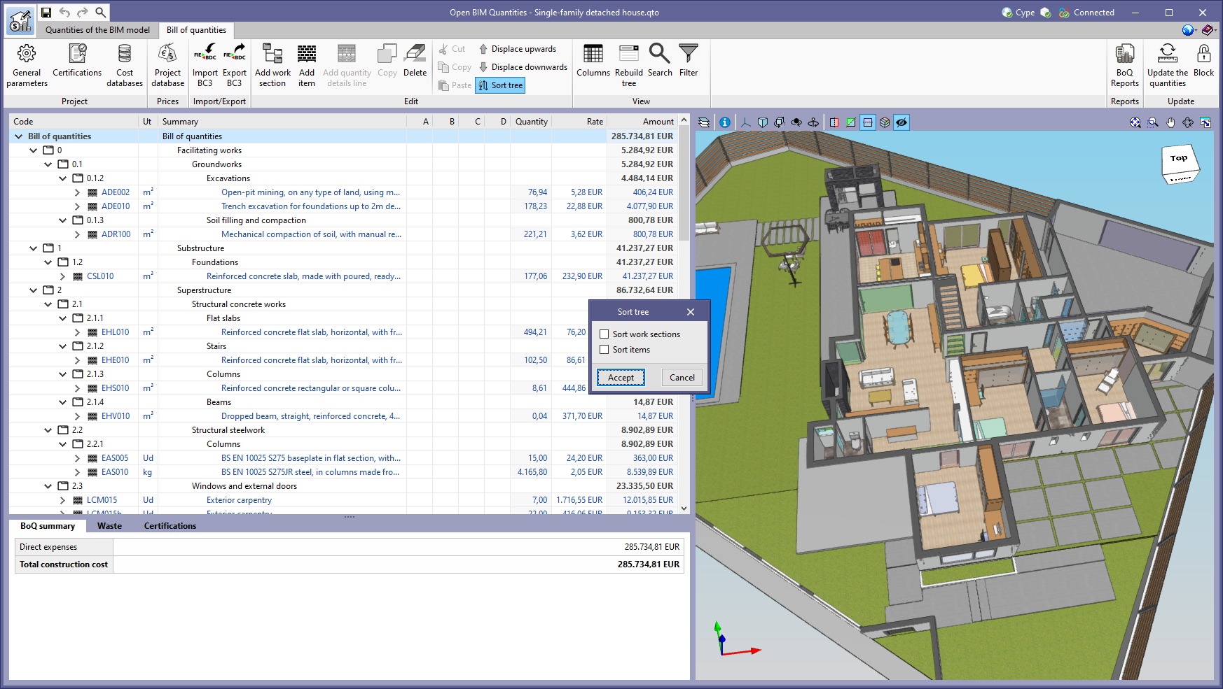
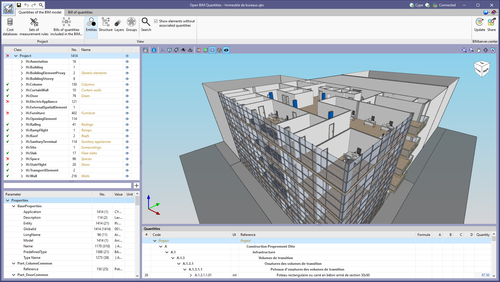
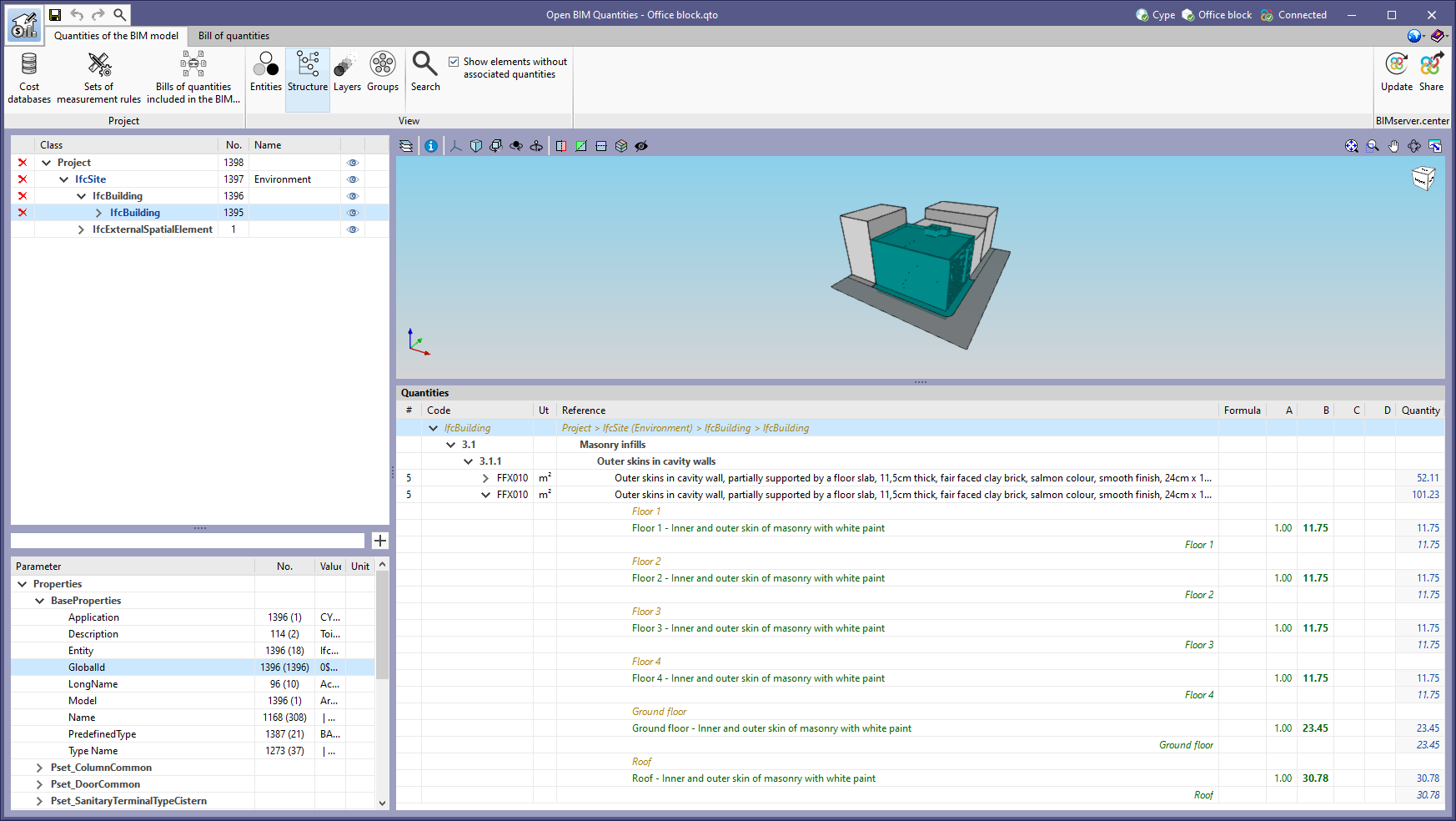
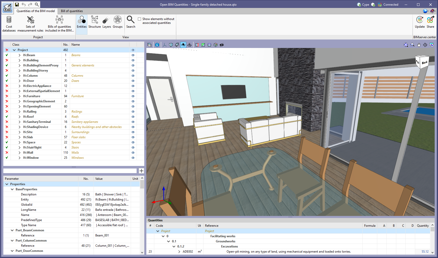
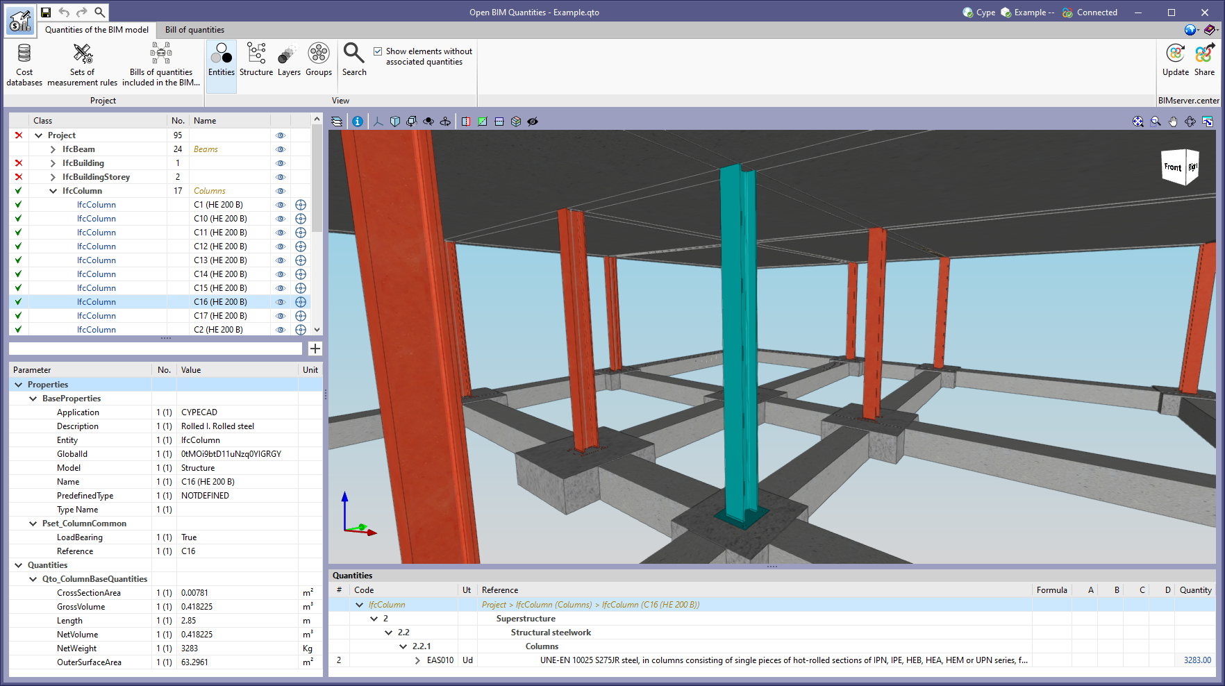
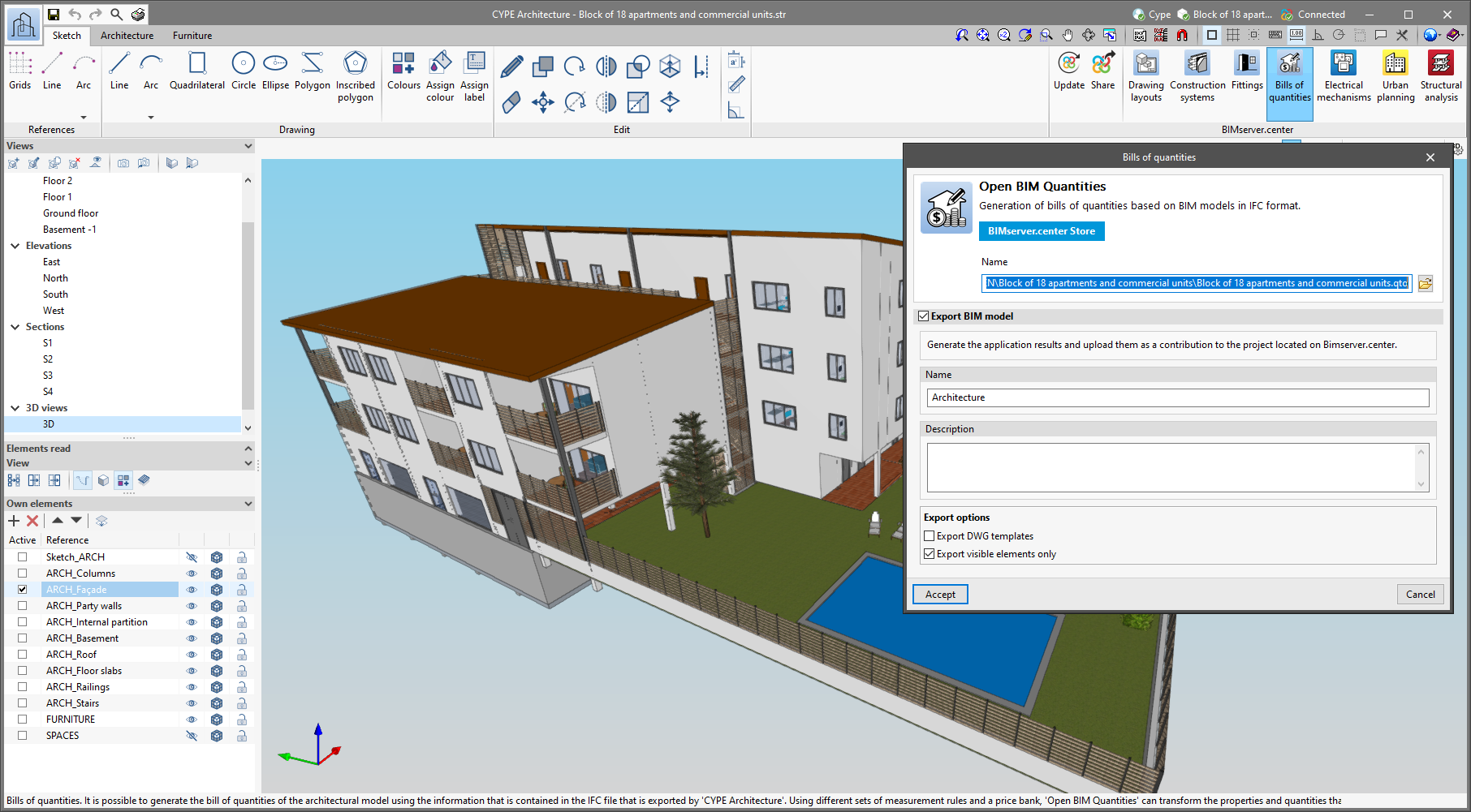
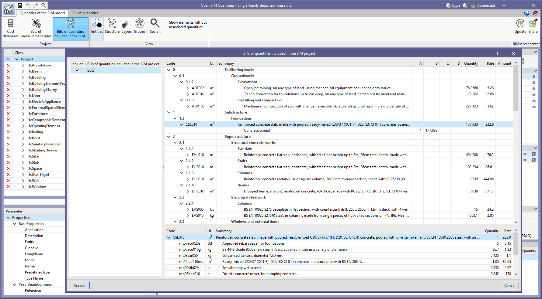
Please note that, in a conventional workflow, the job certification is carried out after the project's bill of quantities has been generated. For this reason, when working on a BIMserver.center project, it is common for the contribution corresponding to the bill of quantities to already exist. However, the Open BIM Quantities application allows you to read the project bill of quantities via the "Bills of quantities included in the BIM project" option, available from the toolbar in the "Quantities of the BIM model" tab. This way, the project's bill of quantities can be loaded directly and certifications can be created on it without the need to re-generate the quantities.

As of this version (2023.b), when using the FIEBDC-3 export format(.bc3), job certifications can also be included. As stated in the FIEBDC-3 standard specification, each certification is exported in a separate file with a ".bc3" extension. The name of the file containing the certification (to origin) will have the same name as the bill of quantities file with the addition (concatenation) of "#certificationNNNN" where NNN is the certification number.

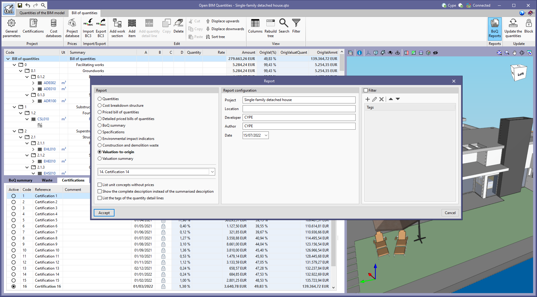
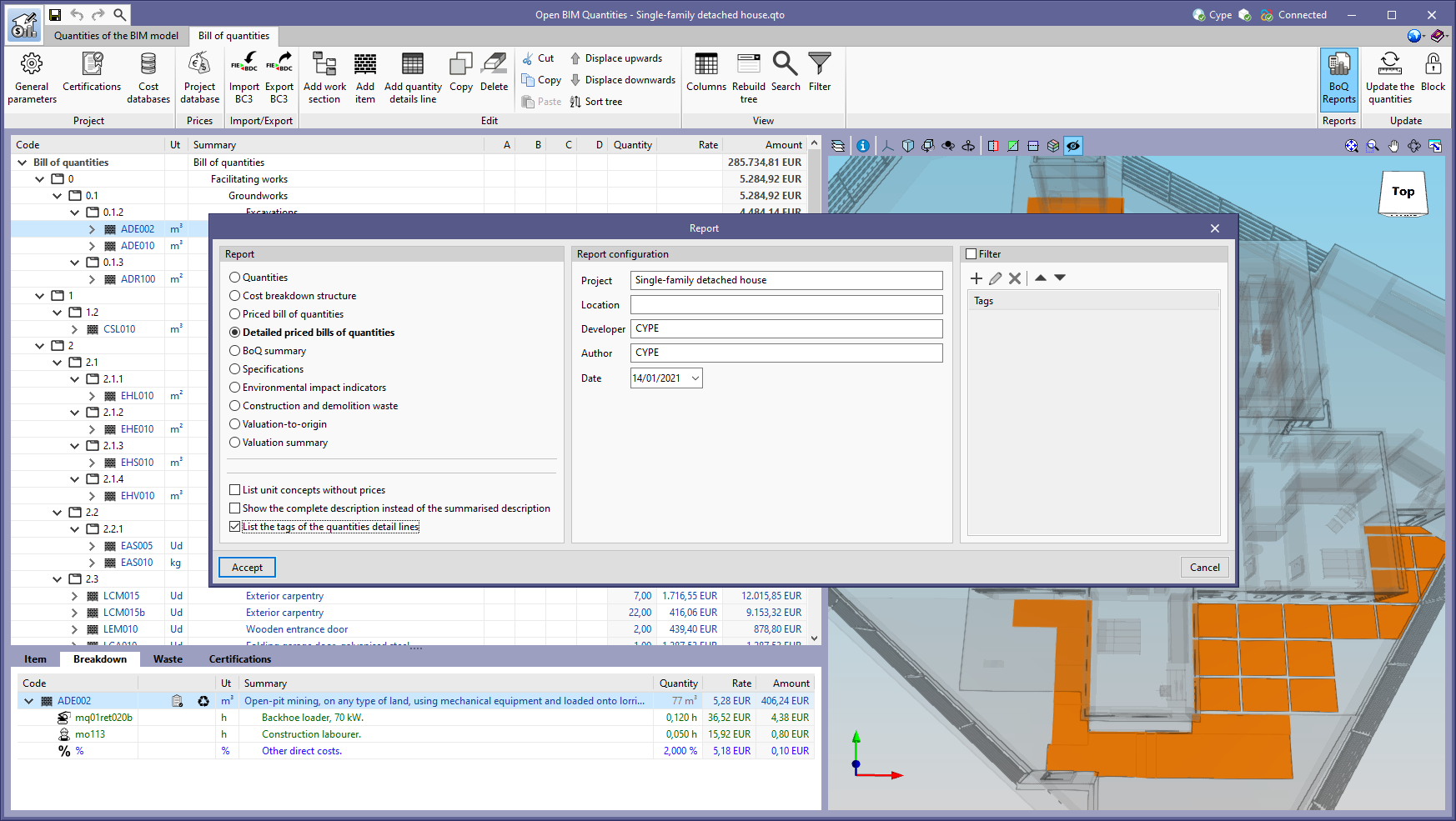
In order to generate the job certification documents, the "Valuation to origin" and "Valuation summary" reports have been added. When selecting one of them from the "BoQ Reports" option in the toolbar, the job certification must be indicated.