New features common to several programs
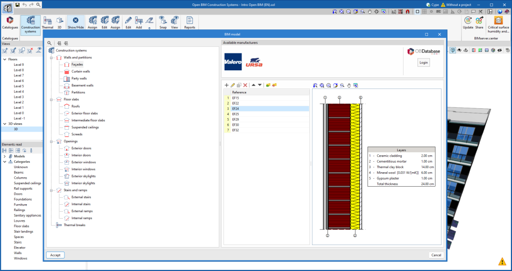
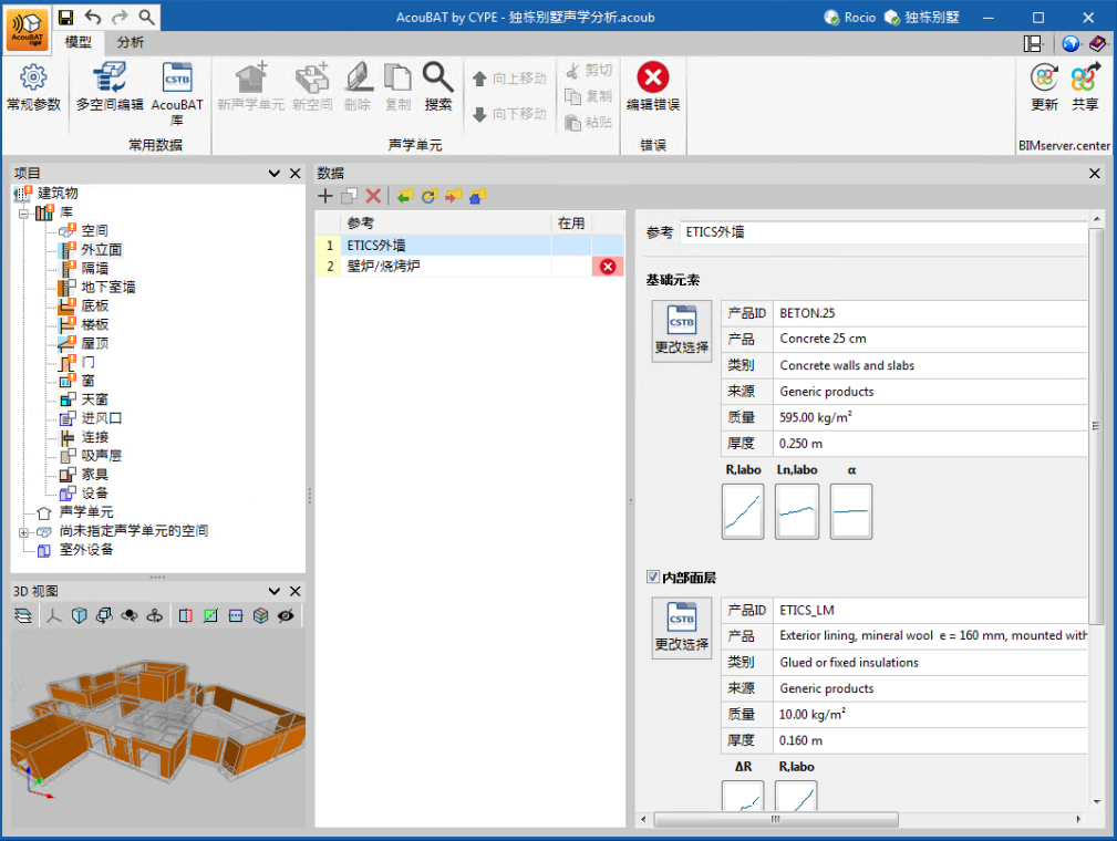
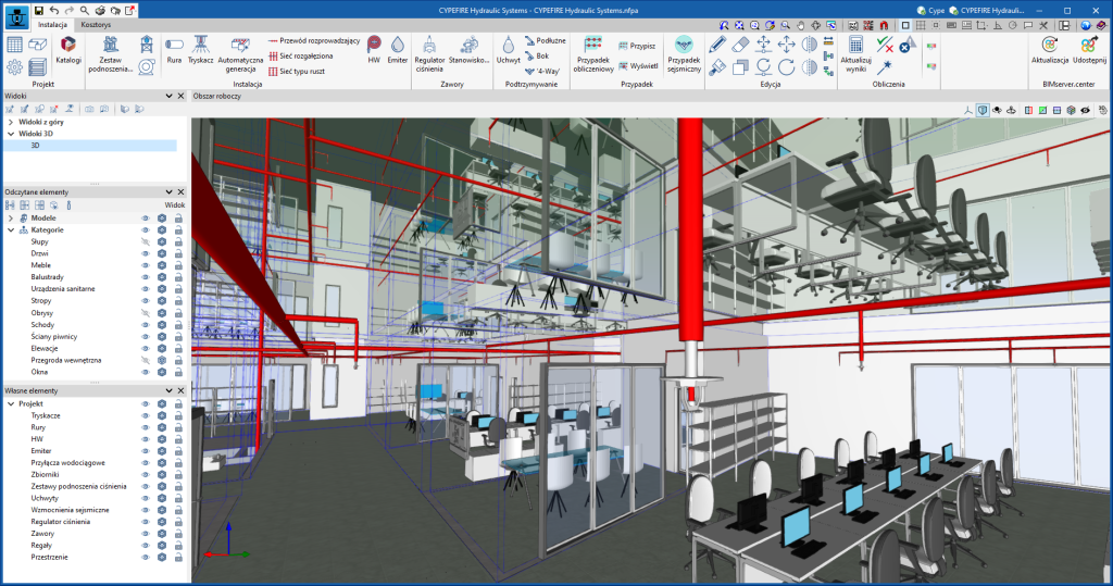
Version 2024.c of the CYPE programs listed below incorporates product libraries from different manufacturers so that they can be downloaded and used in the BIM model generated by the program.
- CYPE Architecture
- CYPE Construction Systems
- CYPELEC REBT
- CYPELEC NF
- CYPELEC PV Systems
- CYPELUX
- CYPELUX CTE
- CYPELUX EN
- CYPELUX SCE
- CYPEPLUMBING Water Systems
- CYPEFIRE
- CYPEFIRE Hydraulic Systems
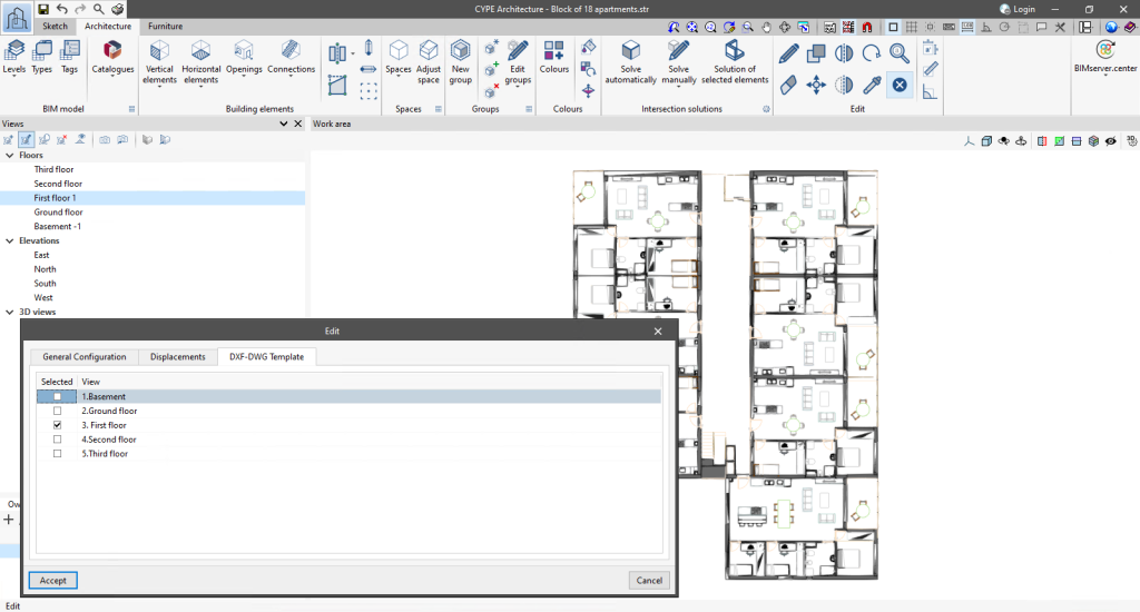
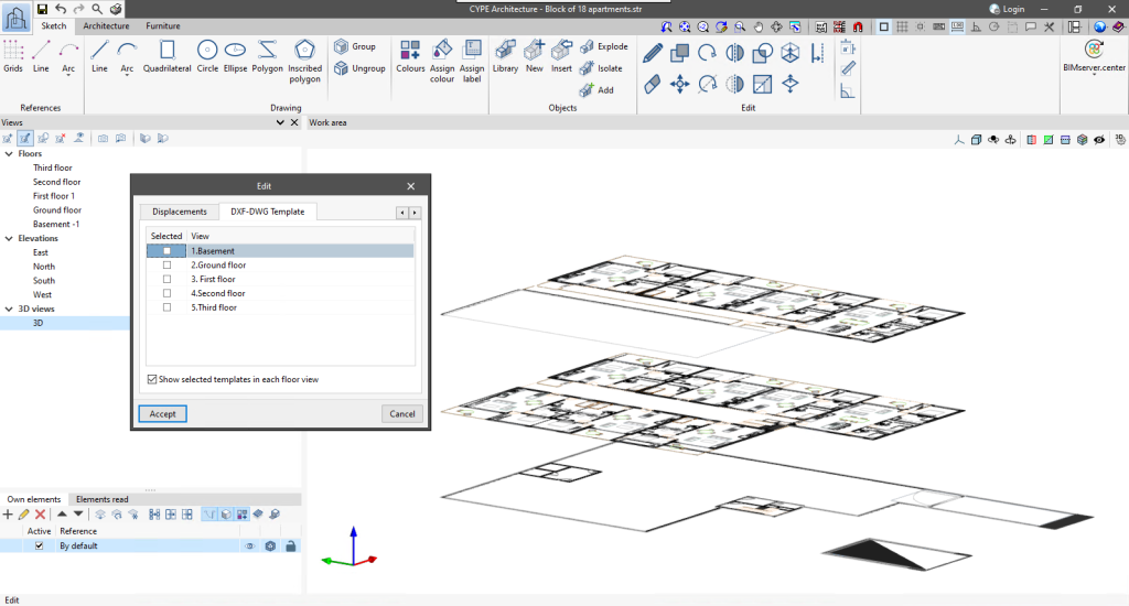
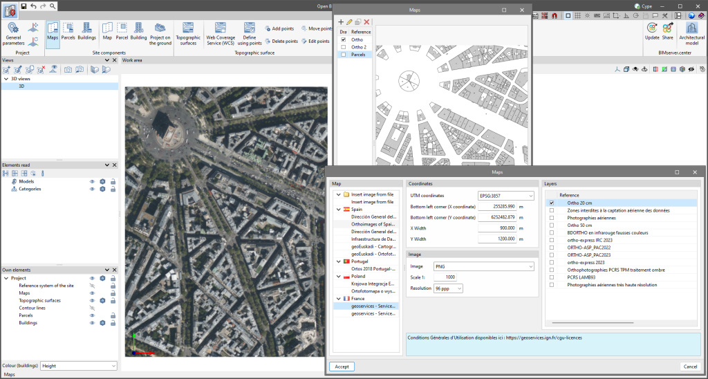
As of version 2024.c, applications with a 3D working environment can manage the visibility of templates from the view configuration panel. For this purpose, the "DXF-DWG templates" tab has been added, where a list of all the templates imported into the project is displayed together with a checkbox to indicate which ones should be shown in the view.
Implementing codes and improving their enforcement
Concrete structures
In version 2024.c of CYPE Connect and StruBIM Steel, the national annexes to Eurocode 2 have been added for the following countries:
- EN 1992-1-1 (Design of concrete structures. Part 1-1: General rules and rules for buildings)
- Germany
DIN EN 1992-1-1/NA:2015 - Austria
ÖNORM EN 1992-1-1/NA:2018 - Belgium
NBN EN 1992-1-1 ANB:2010 - Bulgaria
BDS EN 1992-1-1:2005/NA:2015 - Cyprus
CYS EN 1992-1-1/NA:2019 - Croatia
HRN EN 1992-1-1/NA:2015 - Denmark
DS/EN 1992-1-1 DK NA:2021 - Slovenia
SIST EN 1992-1-1:2005/A101:2006 - Spain
AN/UNE EN 1992-1-1:2015 - Estonia
EVS EN 1992-1-1:2005/NA:2015 - Finland
SFS EN 1992-1-1/NA:2016 - France
NF EN 1992-1-1/NA:2007 - Greece
ΕΛΟΤ EN 1992-1-1:2005/ΝΑ:2010 - Ireland
IS EN 1992-1-1/NA:2010-01 - Italy
UNI EN 1992-1-1/NA:2010 - Latvia
LVS EN 1992-1-1:2005/NA:2020 - Lithuania
LST EN 1992-1-1:2005/NA:2011 - Luxembourg
ILNAS EN 1992-1-1:2004/AN:2020 - Malaysia
MS EN 1992-1-1:2010/NA - Norway
NS EN 1992-1-1:2004/NA:2021 - The Netherlands
NEN EN 1992-1-1+C1:2011/NB:2020 - Poland
PN-EN 1992-1-1:2008/NA:2016-11 - Portugal
NP EN 1992-1-1:2010/AN - United Kingdom
BS EN 1992-1-1:2004/NA:2005 - Czech Republic
ČSN EN 1992-1-1/NA:2011 - Romania
SR EN 1992-1-1:2004/NB:2008 - Serbia
SRPS EN 1992-1-1/NA:2015 - Singapore
SS EN 1992-1-1:2008/NA - Sweden
SS EN 1992-1-1:2005/NA:2010-12 - Switzerland
SN EN 1992-1-1/NA:2014
- Germany
- EN 1992-4 (Design of concrete structures. Part 4: Design of fastenings for use in concrete)
- Germany
DIN EN 1992-4/NA:2019 - Austria
ÖNORM EN 1992-4 - Cyprus
CYS EN 1992-4:2018/NA:2019 - Croatia
HRN EN 1992-4:2019/NA:2022 - Estonia
EVS EN 1992-4:2018/NA:2018 - France
NF EN 1992-4:2018/NA:2022 - Latvia
LVS EN 1992-4:2018/NA:2019 - Norway
NS EN 1992-4:2018/NA:2019 - The Netherlands
NEN EN 1992-4:2018/NB:2019 - United Kingdom
BS EN 1992-4:2018/NA:2019 - Serbia
SRPS EN 1992-4/NA:2020 - Singapore
SS EN 1992-4:2021/NA - Switzerland
SN EN 1992-4/NA:2019
- Germany
Rolled and welded steel structures
In version 2024.c of CYPE Connect and StruBIM Steel, the national annexes to Eurocode 3 have been included for the following countries:
- EN 1993-1-1 (Design of steel structures. Part 1-1: General rules and rules for buildings)
- Germany
DIN EN 1993-1-1/NA:2010-12 - Austria
ÖNORM B 1993-1-1:2007 - Belgium
NBN EN 1993-1-1/ANB:2008 - Bulgaria
BDS EN 1993-1-1/NA:2008 - Cyprus
CYS EN 1993-1-1:2005/NA:2009 - Croatia
HRN EN 1993-1-1:2014/NA:2015 - Denmark
DS EN 1993-1-1 DK/NA:2019 - Slovenia
SIST EN 1993-1-1:2005/A101:2006 - Spain
AN/UNE EN 1993-1-1/NA:2013 - Estonia
EVS EN 1993-1-1:2005/NA:2015 - Finland
SFS EN 1993-1-1/NA:2019 - France
NF EN 1993-1-1/NA:2007 - Greece
ΕΛΟΤ EN 1993-1-1:2009/NA - Ireland
IS EN 1993-1-1/NA:2005 - Italy
UNI EN 1993-1-1/AN:2010 - Lithuania
LST EN 1993-1-1:2005/NA:2011 - Luxembourg
ILNAS EN 1993-1-1:2005/AN-LU:2011 - Norway
NS EN 1993-1-1:2005/NA:2008 - The Netherlands
NEN EN 1993-1-1+C2:2011/NB:2011 - Poland
PN EN 1993-1-1:2006/NA:2010 - Portugal
NP EN 1993-1-1:2010/AN - United Kingdom
BS EN 1993-1-1:2005/NA:2008 - Czech Republic
ČSN EN 1993-1-1/NA:2011 - Romania
SR EN 1993-1-1:2006/NA:2008 - Serbia
SRPS EN 1993-1-1/NA:2013 - Singapore
SS EN 1993-1-1:2010/NA - Sweden
SS EN 1993-1-1/NA - Switzerland
SN EN 1993-1-1/NA:2016
- Germany
- EN 1993-1-8 (Design of steel structures. Part 1-8: Design of joints)
- Germany
DIN EN 1993-1-8/NA:2010-12 - Austria
ÖNORM B 1993-1-8:2015-11 - Belgium
NBN EN 1993-1-8/ANB:2010 - Bosnia
BAS EN 1993-1-8/NA:2019 - Bulgaria
BDS EN 1993-1-8:2005/NA:2011 - Cyprus
CYS EN 1993-1-8:2005/NA:2019 - Croatia
HRN EN 1993-1-8:2014/NA:2014 - Denmark
DS EN 1993-1-8 DK/NA:2019 - Slovenia
SIST EN 1993-1-8:2005/A101:2006 - Spain
AN/UNE EN 1993-1-8:2013 - Estonia
EVS EN 1993-1-8:2005/NA:2006 - Finland
SFS EN 1993-1-8/NA:2019 - France
NF EN 1993-1-8/NA:2007 - Greece
ΕΛΟΤ EN 1993-1-8:2005/NA:2010 - Ireland
IS EN 1993-1-8:2005/NA:2005 - Italy
UNI EN 1993-1-8/AN:2010 - Latvia
LVS EN 1993-1-8:2005/NA:2014 - Lithuania
LST EN 1993-1-8:2005/NA:2010 - Luxembourg
ILNAS EN 1993-1-8/AN-LU:2011 - Norway
NS EN 1993-1-8:2005/NA:2009 - The Netherlands
NEN EN 1993-1-8+C2:2011/NB:2011 - Poland
PN EN 1993-1-8:2006/NA:2011 - Portugal
NP EN 1993-1-8:2010/AN - United Kingdom
BS EN 1993-1-8:2005/NA:2008 - Czech Republic
ČSN EN 1993-1-8:2006/NA:2012 - Romania
SR EN 1993-1-8:2006/NB:2008 - Serbia
SRPS EN 1993-1-8:2012/NA:2013 - Singapore
SS EN 1993-1-8:2010/NA:2016 - Sweden
SS EN 1993-1-8/NA - Switzerland
SN EN 1993-1-8:2005/NA:2016
- Germany
Cold-formed steel structures
Loads on structures. Wind loads
Loads on structures. Seismic loads
Reglamento INPRES - CIRSOC 103. Reglamento argentino para construcciones sismorresistentes. Parte I – Construcciones en general (2018).
Reglamento INPRES - CIRSOC 103. Reglamento argentino para construcciones sismorresistentes. Parte II – Construcciones de hormigón armado (2021).
Implemented in CYPECAD and CYPE 3D.
Loads on structures. Snow loads
Safety in case of fire
Improvements in the implementation of the SCIE regulation with Portaria n.° 135/2020, de 2 de junho (Portugal)
In version 2024.b, the Portuguese fire safety regulation "Regulamento Técnico de Segurança contra Incêndio em Edifícios (SCIE)" was implemented in CYPEFIRE for projects of type "Utilização-tipo I - Habitacionais". Version 2024.c extends the types of projects that can be solved in CYPEFIRE with the SCIE regulation according to "Portaria n.° 135/2020, de 2 de junho" and they are as follows:
- Utilização-tipo II «Estacionamentos»
- Utilização-tipo III «Administrativos»
- Utilização-tipo IV «Escolares»
- Utilização-tipo V «Hospitalares e lares de idosos»
- Utilização-tipo VI «Espectáculos e reuniões públicas»
- Utilização-tipo VII «Hoteleiros e restauração»
Plumbing
Gas
CYPE Architecture
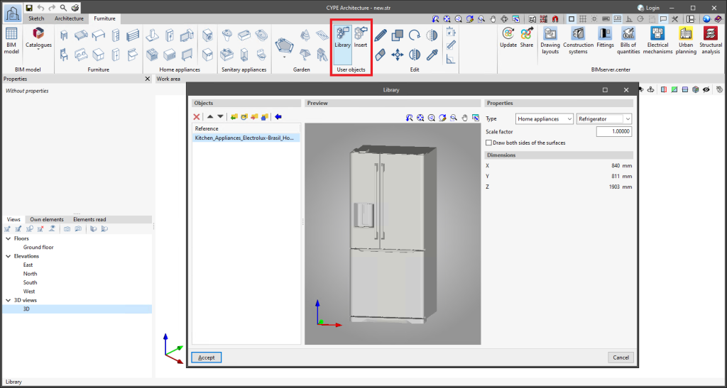
CYPE Architecture allows users to import furniture objects and create their own library. The library allows objects to be imported in ".ifc", ".obj" and ".step" formats.
In the "Furniture" tab, there is now a new "User objects" section with two options:
- Library
From here, users can import objects and create their own library that can be used in the current project or in other CYPE Architecture projects. The library also allows users to modify the properties of the imported object (type, scale factor, drawing both sides of the surface areas). - Insert
This option is used to insert the objects available in the user library. When searching for objects to insert them, they are sorted according to the classification indicated in the library.
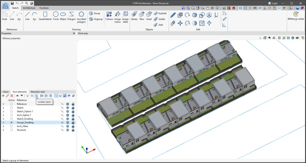
The "Isolate layer" option has been implemented in the "Own elements" section. This option allows users to isolate the active layer, turning off the rest of the layers available in the project.
To turn all the layers of the project back on, simply click on the visibility column of the project's own elements and select "Show all".
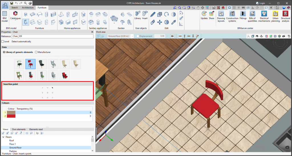
Version 2024.c includes two improvements concerning the insertion point:
- New "Edit insertion point" receiver
This new receiver can be found in the "Building elements" section of the Architecture tab. It allows multiple editing of the insertion point of beams and columns. - Furniture objects allow the insertion point to be selected when the furniture is entered.
Open BIM Construction Systems
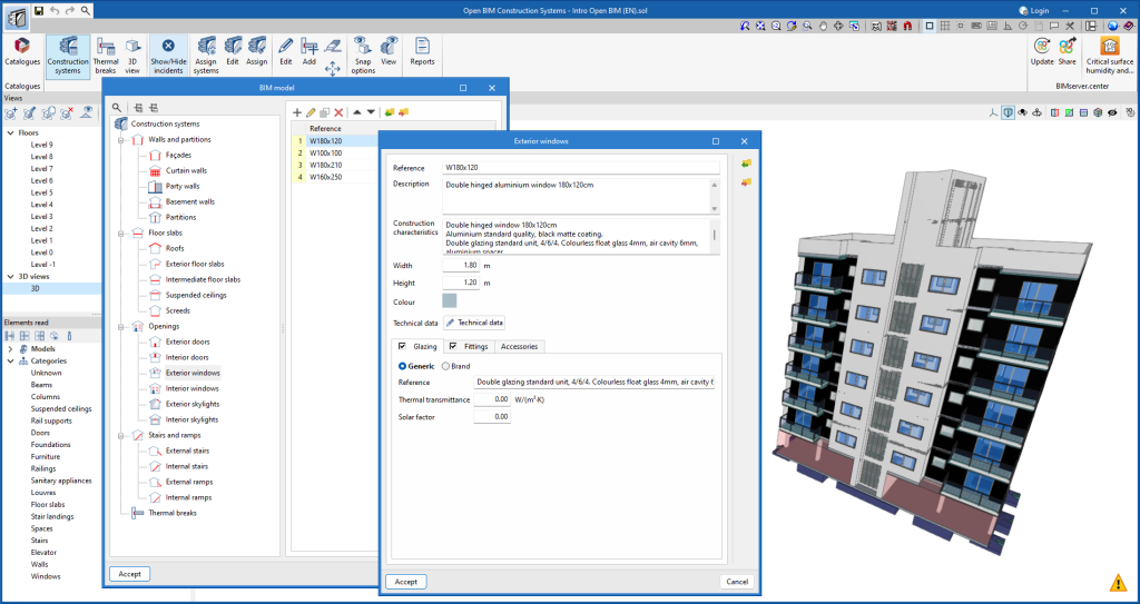
The following changes have been made to the definition of windows, doors and skylights:
- The "Height" and "Width" fields have been added.
- In windows and skylights, the characteristics for "Glazing", "Fittings" and "Accessories" have been separated into tabs. The technical data associated with the glazing and fittings can be found within these tabs.
- Manufacturer products can now be selected when defining the fittings.
IFC Builder
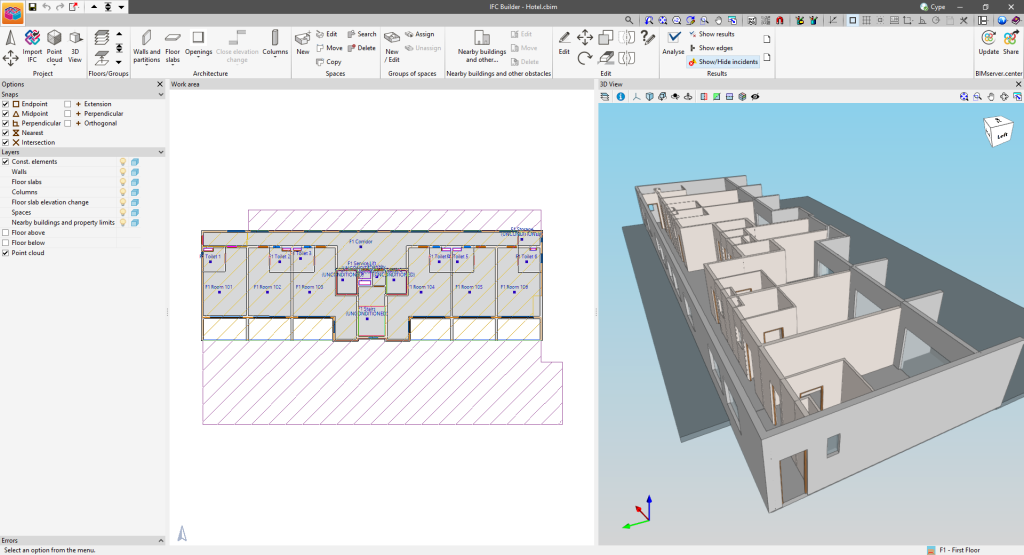
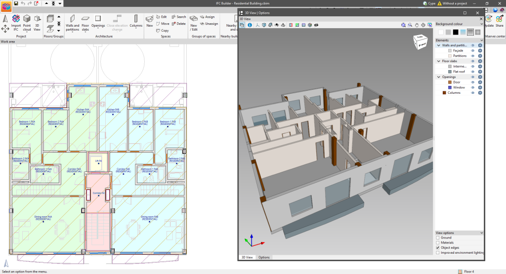
As of version 2024.c, IFC Builder includes the new dockable window system (implemented in other programs in version 2023.e) which replaces the main screen user interface. The interface is now composed of the "Work area", "Options" and "3D View" windows. These can be moved and resized. These windows can be floating windows, pinned to a location within the main application dialogue box, dragged out of the main application dialogue box, or even moved to another monitor.
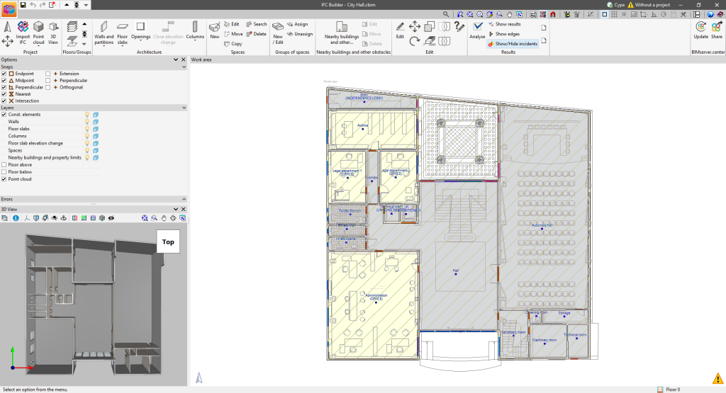
The following changes have been made to the layout of the application toolbar buttons:
- The toolbar tabs have been grouped into a single menu.
- The options for "Point cloud", "Walls and partitions", "Floor slabs", "Openings" and "Columns" are now drop-down menus.
- The option to import an IFC file has been added to the toolbar via the "Import IFC" option. This way, importing is not needed during the process of creating a new job.
CYPECAD
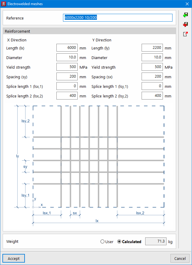
As of version 2024.c, CYPECAD now allows users to include electrowelded mesh for use in the analysis of flat slabs in a similar way to the use of the base reinforcement. As well as designing the reinforcement taking into account the electrowelded mesh, the program also allows users to detail the reinforcement, obtain reports and drawings as well as detailed measurements of the reinforcement.
Electrowelded meshes are part of a new CYPECAD module, so in order to use them, users must have the corresponding permission in their user license.
Electrowelded mesh and base reinforcement
For analysis purposes, the electrowelded mesh and the base reinforcement are treated in the same way, bearing in mind that, when designing the slab reinforcement, both elements provide a uniform mechanical ratio throughout the slab.
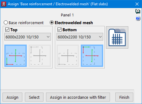
For flat slabs, the program now allows users to choose between assigning base reinforcement or electrowelded mesh.
When selecting the "Electrowelded meshes" option, the program allows users to choose from all the references defined in the library. New meshes can be added to the library by defining their reference and characteristics.
The X and Y axes of the mesh can be made to coincide with the reinforcement axes of the slab, or they can be rotated by 90°.
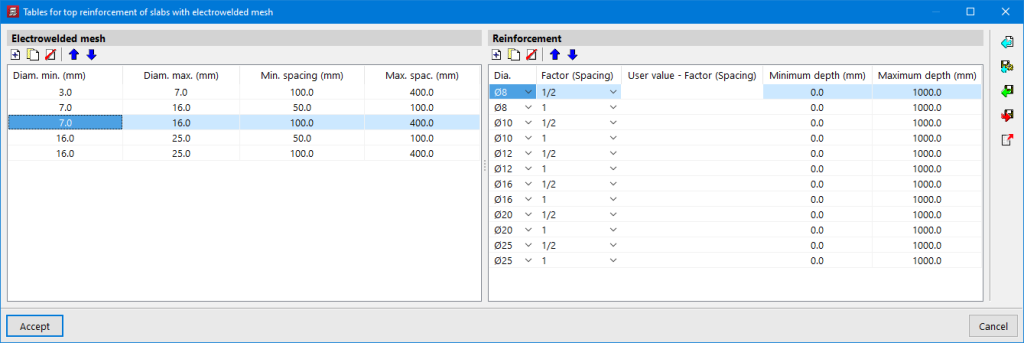
The program designs the necessary reinforcement bars in addition to the mesh, using the reinforcement tables for slabs with electrowelded mesh.
Editing electrowelded meshes
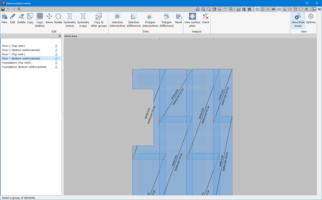
If meshes have been assigned to any of the panels, the "Electrowelded meshes" option will be activated in the "Flat/Waffle slabs" menu in the "Results" tab. After analysing the job, the program will automatically generate a mesh distribution proposal for the top and bottom reinforcement of the flat slab sections, which can be checked and modified using this option (Electrowelded meshes). The editor allows users to delete, move and trim the existing meshes. It also includes different features to make it easier to enter new mesh in the desired areas.
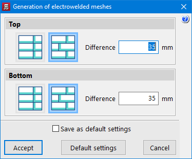
The criteria for automatically generating the mesh distribution can be configured in the menu "Job" > "Floor slab options" > "Generation of electrowelded meshes".
The layout of the electrowelded meshes should ensure that the floor slab panel is completely covered by the mesh panels, taking into account that each panel should overlap with the next one in the overlapping area.
Electrowelded meshes report
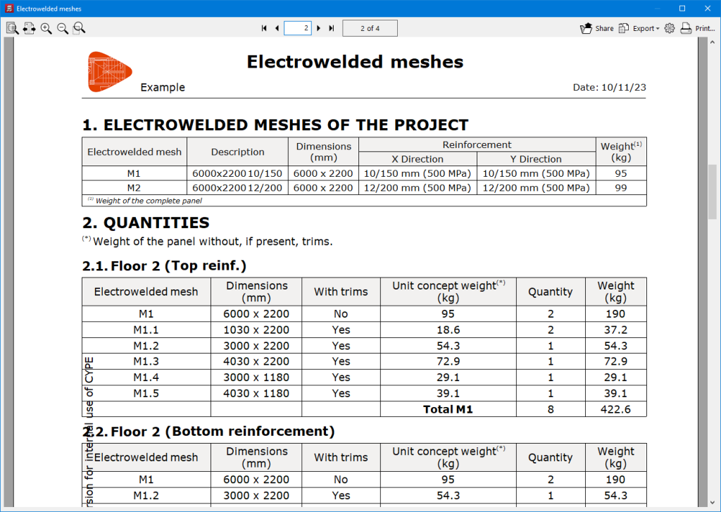
The "Reports" menu of the program includes the new "Electrowelded meshes" report, which contains information on the types of mesh used in the job as well as their characteristics and the quantity of panels per floor, taking into account, where appropriate, the necessary trimming to adapt them to the geometry of the floor slab.
Electrowelded meshes drawing
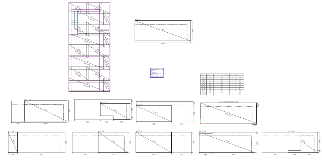
The "Drawings" menu of the program includes the new "Electrowelded mesh" type of drawing. As with other CYPECAD floor plans, the elements to be shown can be configured in this drawing by means of a series of options.
The drawing shows a floor with the layout of the electrowelded meshes, a detailed model of the different meshes used in the job, and details of each of the trimmed panels. A summary table with the quantities and weights of each of the elements in the drawing is also included.
CYPECAD version 2024.c includes the following improvements and corrections to the program for some specific cases:
- The "Redesign" option has been added ("Results" tab > "Flat/Waffle slabs" menu. This option already existed in the same menu, in the "Match reinforcement" option. By launching it, the groups of flat or waffle slabs in which any modifications have previously been made to the base reinforcement, electrowelded mesh or matching lines are redesigned.
- An error that occurred when checking contour lines when a minimum value was set higher than the maximum value of the current view has been fixed.
- An error that occurred in "BIMserver.center > Share" if there was a corbel associated with a column that was exempt on the lower floor has been fixed.
- In "General options" > "General drawing options", users can now display the axes corresponding to the symbols of the flat slab floors identified with a red colour for the X-axis direction and a green colour for the Y-axis direction.
- The import of IFCs for walls where the program that generates the IFC does not describe the material layers has been improved. In these cases, the wall thickness is obtained from the specific property for the measurement.
- In the frame editor, an error that could occur in some specific cases when extending a reinforcement bar after having changed the "Assembly options" to "On-site" has been fixed.
- The export to Arquimedes and BC3 files has been improved. For the blinding concrete surface, a value of 0 was previously exported for a foundation beam in contact with slabs on the ground, which was not embedded in a slab.
- An error that could very occasionally occur in "Results > Envelope > Analytical Model" and in "BIMserver.centre > Share" if the "Analytical Model" option was checked, has been fixed.
- The 3D view of walls has been improved. In the case of beams embedded in the wall, the lower and upper sections of the wall overlapped with the beam. This has occurred since version 2022.c due to the changes made for the implementation of "Concrete wall continuous reinforcement in intermediate floors".
- The drawing of "Sections" has been improved. In waffle slabs with different rib widths in x and y, these would be displayed as interchanged.
- An error that occurred when a wall was in contact with a slab whose plane was not parallel to the plane assigned to the beam associated with the wall has been solved. A warning is now displayed so that users can resolve this situation.
- An error that occurred when generating the "Reinforced concrete and masonry wall elevations" drawing in the case of walls in contact with timber joist floor slabs has been fixed.
- An error in the geometry check options of the groups has been fixed. After the check was carried out, the information for linear or point loads outside the plan was not displayed. This error appeared in version 2024.a when another error was fixed.
- An error that could very rarely occur when displaying the 3D view of a job in which non-rectangular pile caps had been defined and which had intersections with centring or tie beams, has been fixed.
- An error that occurred when checking envelopes of composite beams has been fixed. Due to a correction in a recent version, this error arose and only affected composite beams.
- The update of DXF/DWG templates has been improved. When updating templates, if new layers appear, they are made visible automatically. Before, they had to be activated manually.
- The "Beams" > "Define beam" and "Beams > Adjust" snaps have been improved. The "Columns", "Walls" and "Beams" lines from "BIM model templates" are now taken into account.
- The copying of "Editing resources" from one floor to another has been improved. Results no longer need to be lost in order to make a copy of these elements.
- The checking of the flexural strength of columns, in accordance with ACI 318-19 Article 18.7.3.1, by considering the increased axial force in addition to the continuity of the column above the checking point has been improved.
CYPE 3D
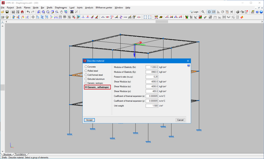
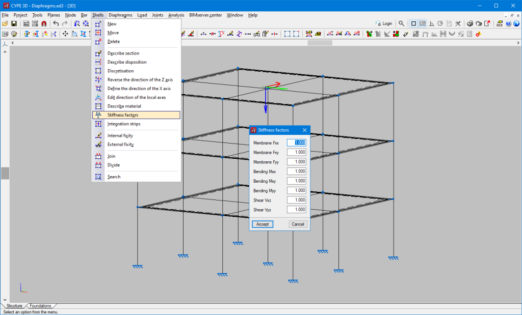
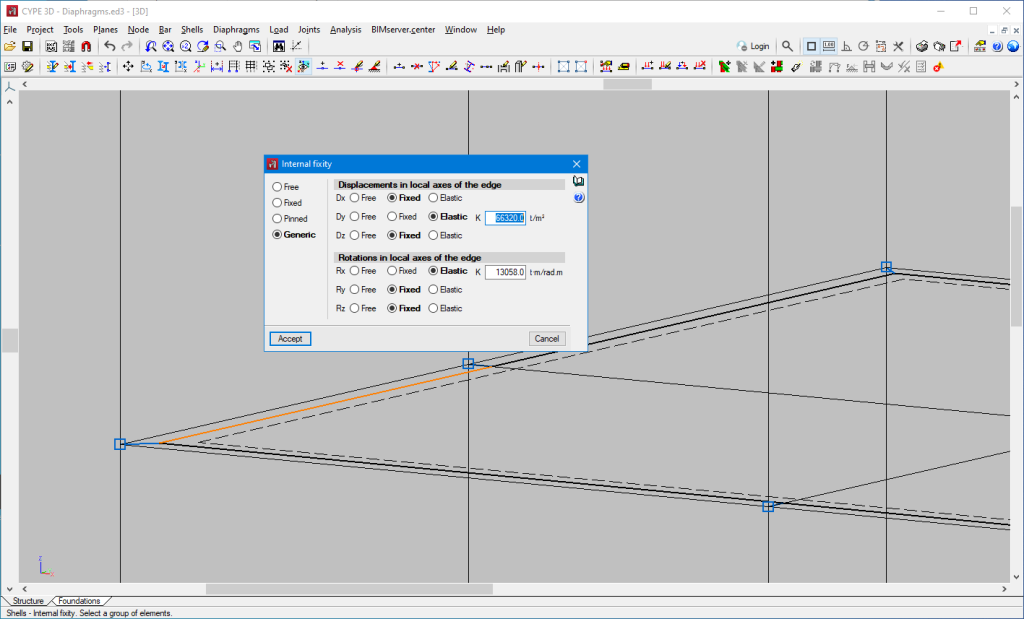
In version 2024.c rigid diaphragms have been implemented in CYPE 3D. The relative displacements between nodes belonging to the same rigid diaphragm are restricted. Therefore, each diaphragm can only rotate and move as a whole.
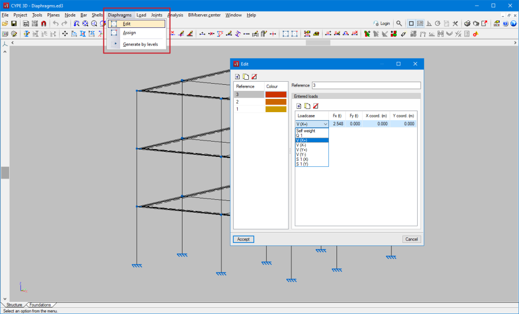
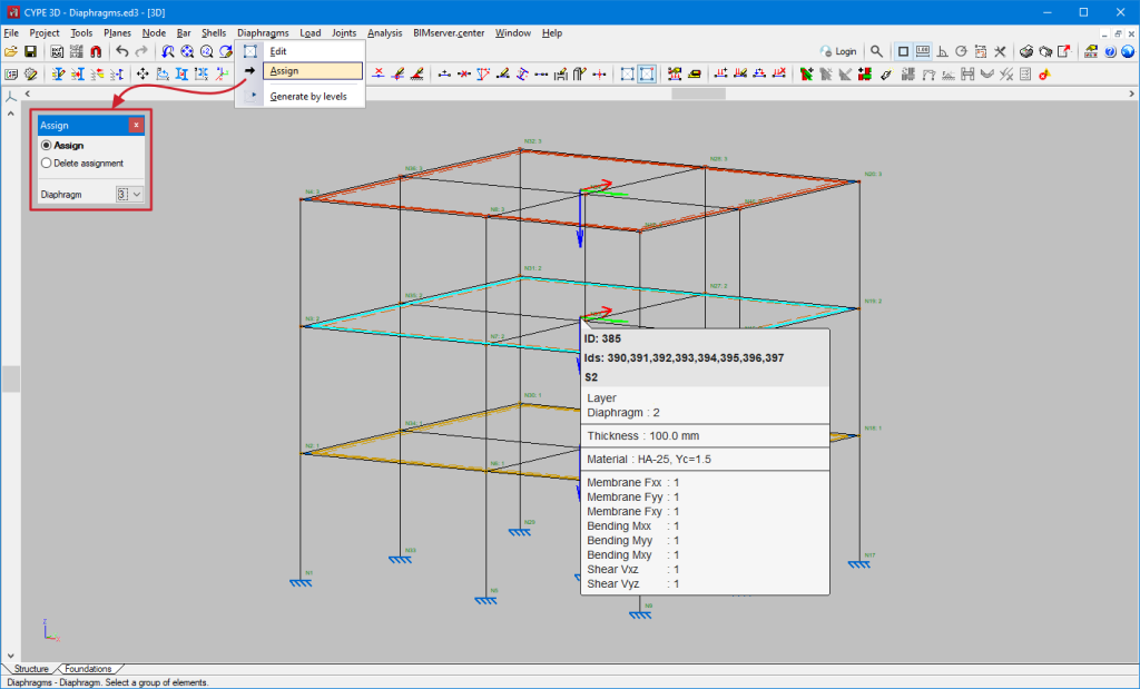
In the "Diaphragms" menu the following options can be found:
- Edit
Allows users to define and edit the diaphragms. Loads can be defined for each diaphragm. To do this, in the "Entered loads" table, users can select the loadcases, the load in the global "X" direction, the load in the global "Y" direction and the coordinates of the application point.
- Assign
Allows users to assign a diaphragm to a selection of nodes or shells. Furthermore, the assignment can be removed.
- Generate by levels
If levels have been defined, this tool generates a diaphragm for each level and assigns that diaphragm to all nodes in the level.
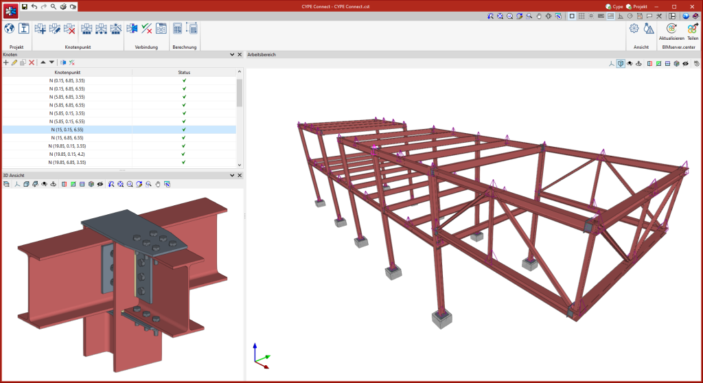
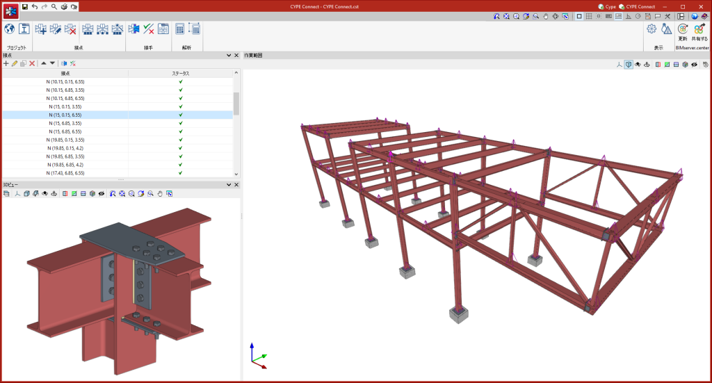
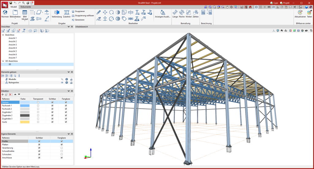
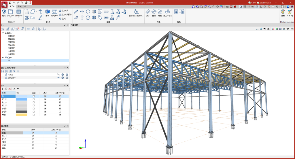
CYPE Connect / StruBIM Steel
As of 21 September 2023, all downloads of the CYPE Connect and StruBIM Steel applications (versions 2024.b and later) from the the BIMserver.center platform will be available for installation in German and Japanese.
These applications can now be installed in the following languages:
- Catalan
- English
- French
- German
- Italian
- Japanese
- Polish
- Portuguese
- Russian
- Spanish
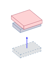
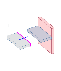
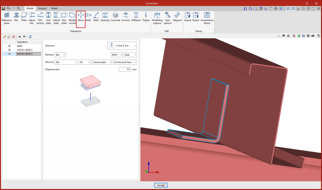
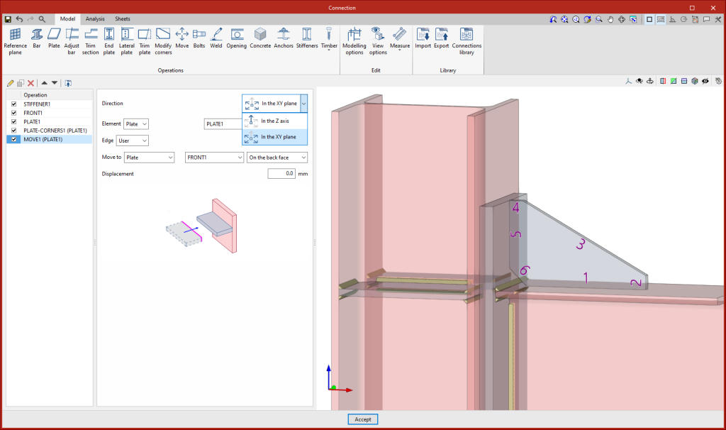
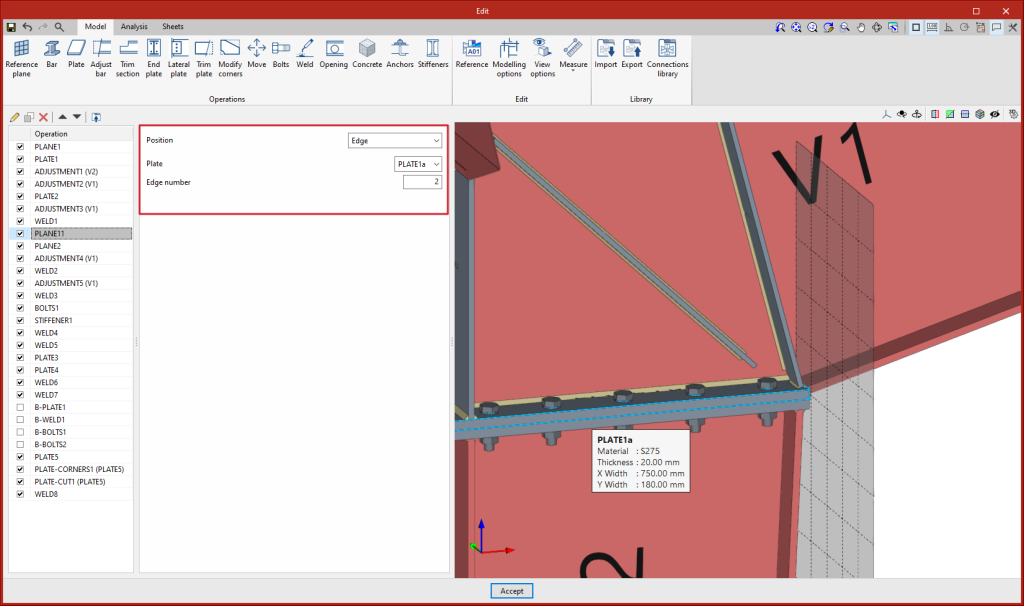
A new operation has been implemented to move bars or plates taking another element as a reference. This operation has two options, to move in the direction of the "z" axis or to move in the "xy" plane of the selected element. By means of these movements, the position of one element is linked to another. Should the reference element change its dimensions or position, the selected element will automatically move with it.
- In the Z axis
Moves a plate or a bar, starting from the selection of one of its plates, in parallel until one of its faces attaches to the face of another element. To perform this movement, both faces must be parallel.
- In the XY plane
Moves a plate, in its plane, until one of its edges reaches the plane defined by the face of another plate. It also moves a bar, from the selection of one of its plates, in the plane of the plate until one of its edges reaches the plane defined by the face of another plate.
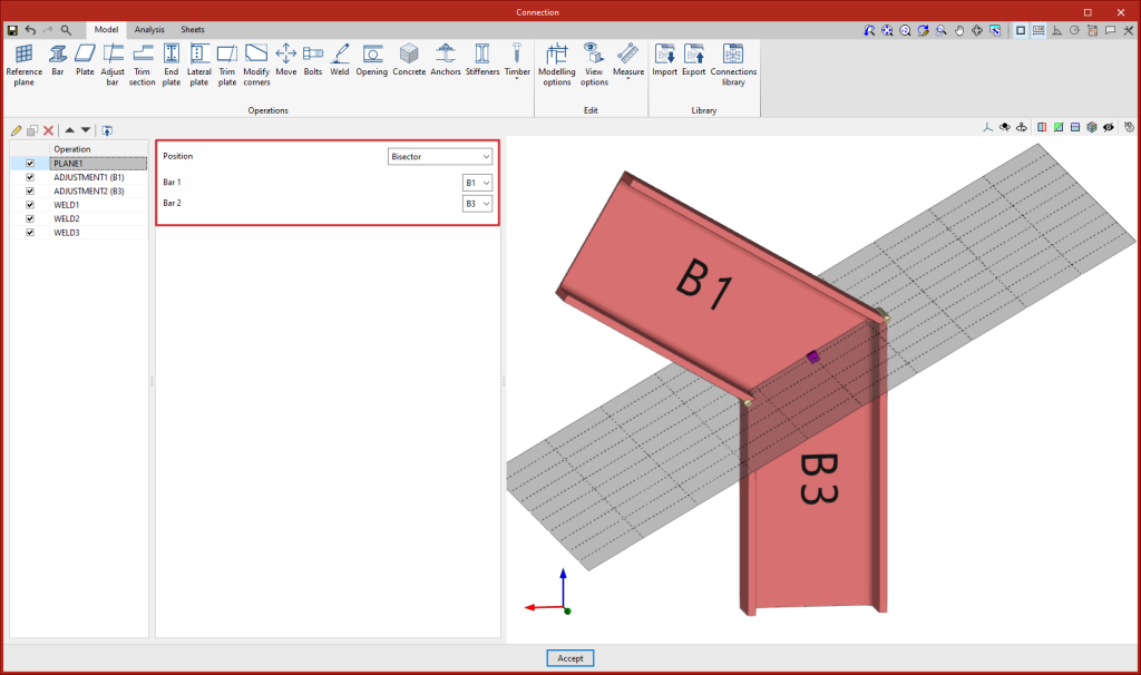
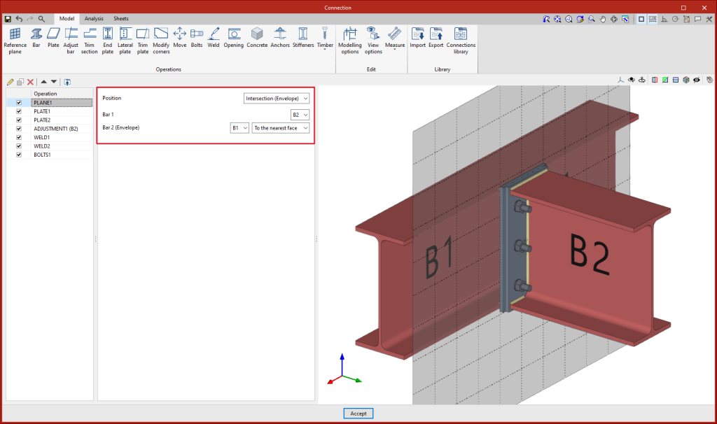
As of version 2024.c, the "Reference plane" operation includes the "Intersection (Envelope)" option to define reference planes at the intersection between a bar and the envelope of another bar. This plane can be used as a reference for attaching plates, adjusting bars, etc.
Options existing up to 2024.c allow planes to be defined in any position, the advantage of using these new options is that the position of the plane is referenced to other elements so that if the dimensions or the position of the bars change, the position of the plane will also change. This is particularly useful when combined with the use of the connection library.
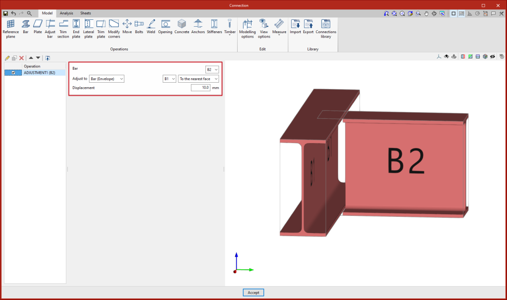
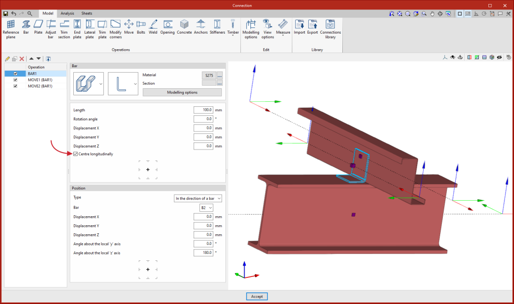
As of version 2024.c, the "Adjust bar" operation includes the option for adjusting bars to the envelope of other bars. Up until version 2024.c, to make a similar adjustment in the case of the web of an open section, users had to adjust and apply a displacement, which varies according to the width of the bar.
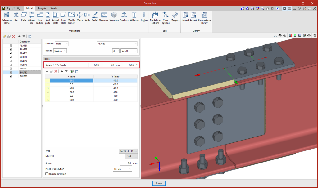
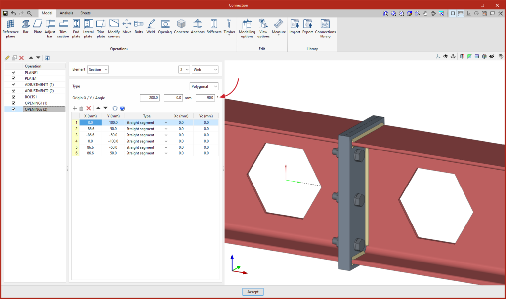
The editing of the origin of the local reference system of openings, bolts and anchors has been implemented. Above the coordinate editing table, the "Origin" section appears with the editing of the "X" and "Y" displacements and the rotation angle. These displacements are applied to the group of elements contained in the table. For bolts, the original reference system corresponds to that of the first plate, for anchors and openings it corresponds to that of the selected plate.
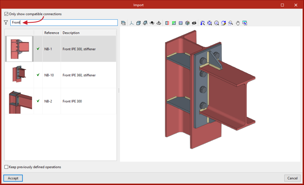
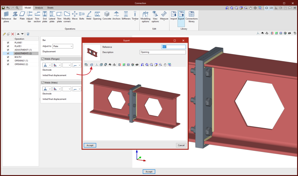
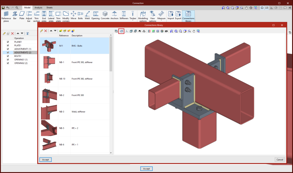
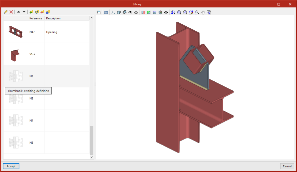
As of version 2024.c, the connection library includes a thumbnail view of the connection. This view helps users to locate connections. The export panel shows a thumbnail view by default. Clicking on "Capture the current view" will update the thumbnail by capturing an image of the 3D view.
The connections saved in the library prior to version 2024.c will appear with the thumbnail yet to be defined. To capture the thumbnail, simply click on "Capture the current view (Thumbnail)".
StruBIM Steel
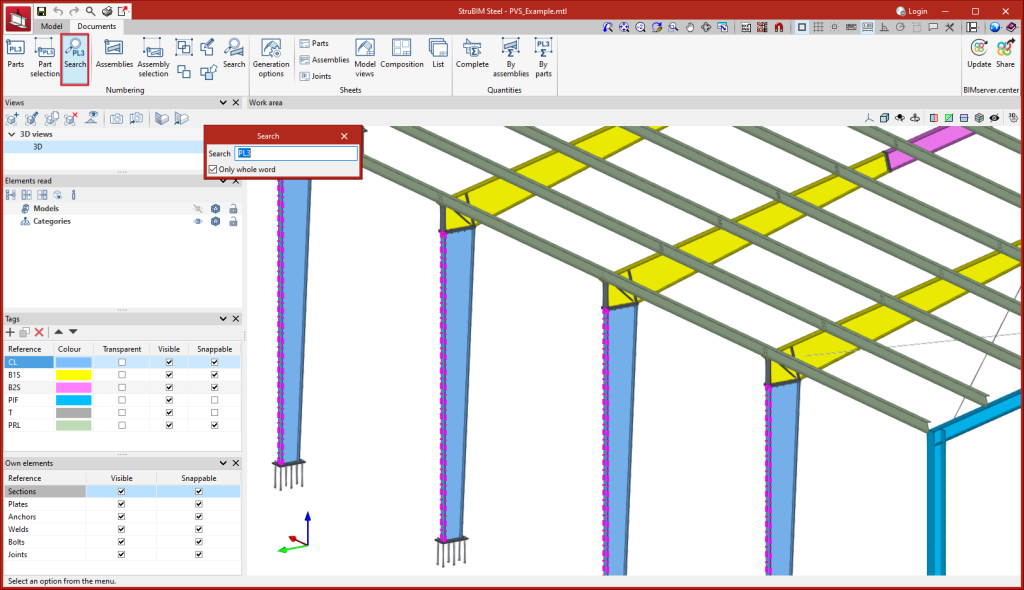
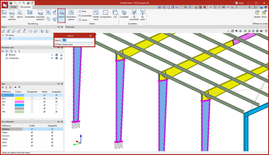
Two new search tools are implemented in StruBIM Steel version 2024.c, one to search for parts and one to search for assemblies. When selecting the tools a panel appears that allows users to enter the reference to be searched for, in the 3D view the elements corresponding to the search will be marked.
CYPEFIRE
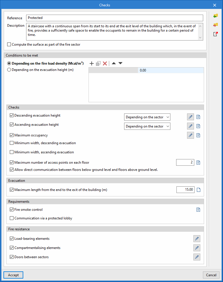
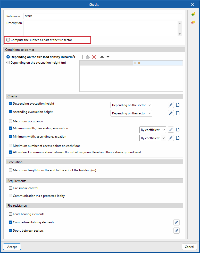
As of version 2024.c of CYPEFIRE, users can manage the maximum distance travelled from the end of the staircase in the check panel ("Evacuation" section, "Maximum length from the end to the exit of the building" option).
To do this, simply activate the check on the panel and specify the maximum permissible distance.
Evacuation origins are used to associate the occupation (or part of it) of a space with an evacuation route, in order to check evacuation paths, lengths and exits.
This new tool allows us to consider the evacuation of spaces which, due to their characteristics, do not require an evacuation route in their interior (dwellings) or which, due to their size or geometry, do not require one either.
It can also be used to distribute the occupation of a single space over different spans of the evacuation route.
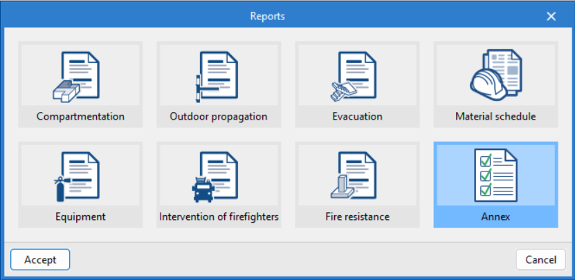
In the management of the reports, a new type of report, the Annex, has been included. In this report, users can find additional information on the fire sectors included in the project.
This information can be checked, modified and created from the checks applicable to each of the fire sectors in the standard.
CYPEFIRE / CYPEFIRE Hydraulic Systems
In order to improve user experience and learning, the categorisation of errors displayed by CYPEFIRE and CYPEFIRE Hydraulic Systems has been improved.
All errors are now ranked from most serious to least serious and both programs will display the highest ranked errors first. In most cases, the correction of these errors solves less serious errors and also displaying and correcting them in stages can contribute to a better understanding of the job.
CYPETHERM EPlus
New descriptive report of the thermal envelope in the simulated model and limit transmittance checks
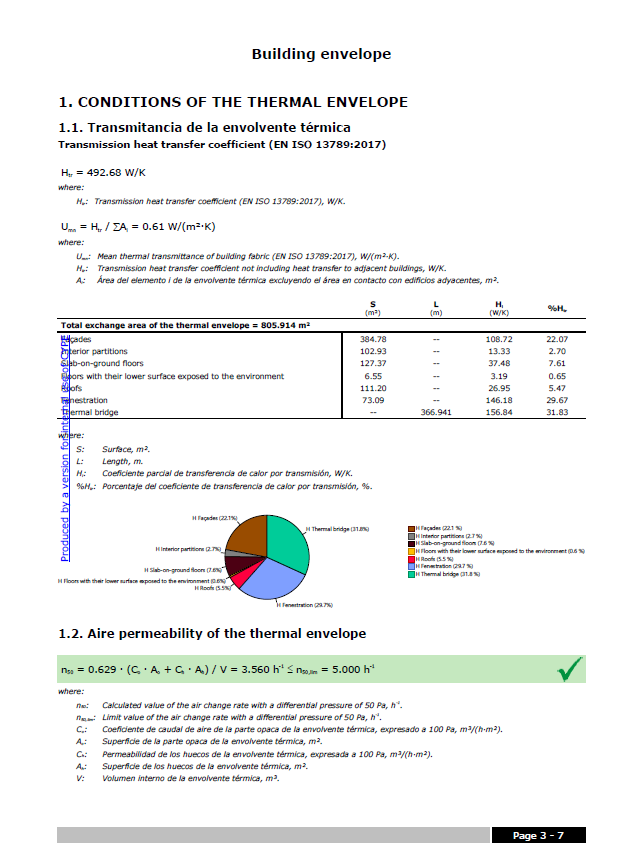
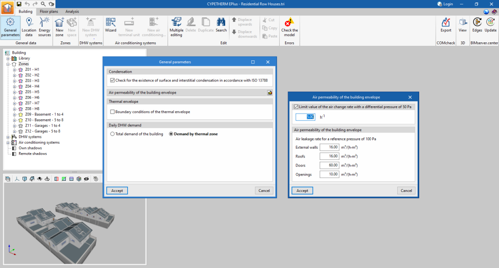
The results output of the program has been enhanced with the new "Building envelope" report, available in the toolbar of the "Analysis" tab. This new report, which can be accessed without having to analyse the model, provides the results of the transmission heat transfer coefficient calculated according to EN ISO 13789:2017 and the air permeability of the thermal envelope. A breakdown by elements is provided and the thermal transmittance (U) value of each element is compared with the limit value set by the user.
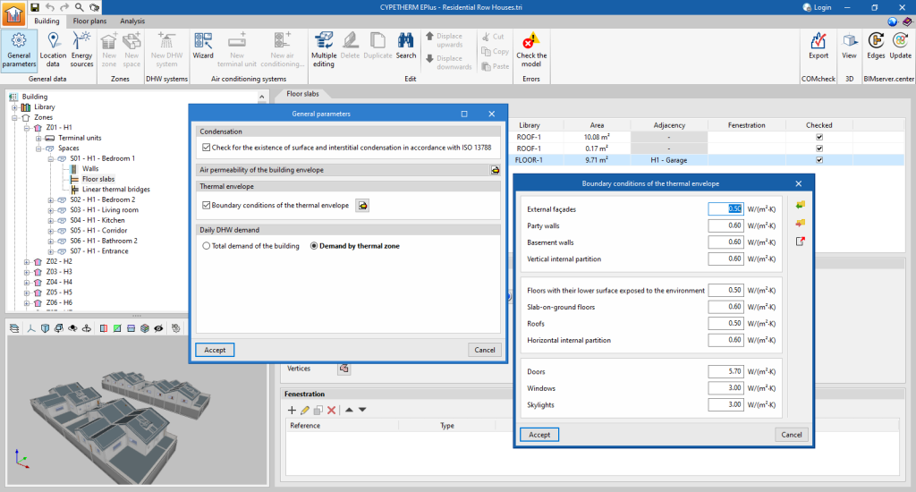
The limit transmittance values for each type of building element can be set in the "Building" tab, under "General parameters", where the new "Thermal envelope" section appears. By activating the "Boundary conditions of the thermal envelope" checkbox, the program will check the limit transmittance of the building elements both in the "Check" button of the model and in the new "Building envelope" report.
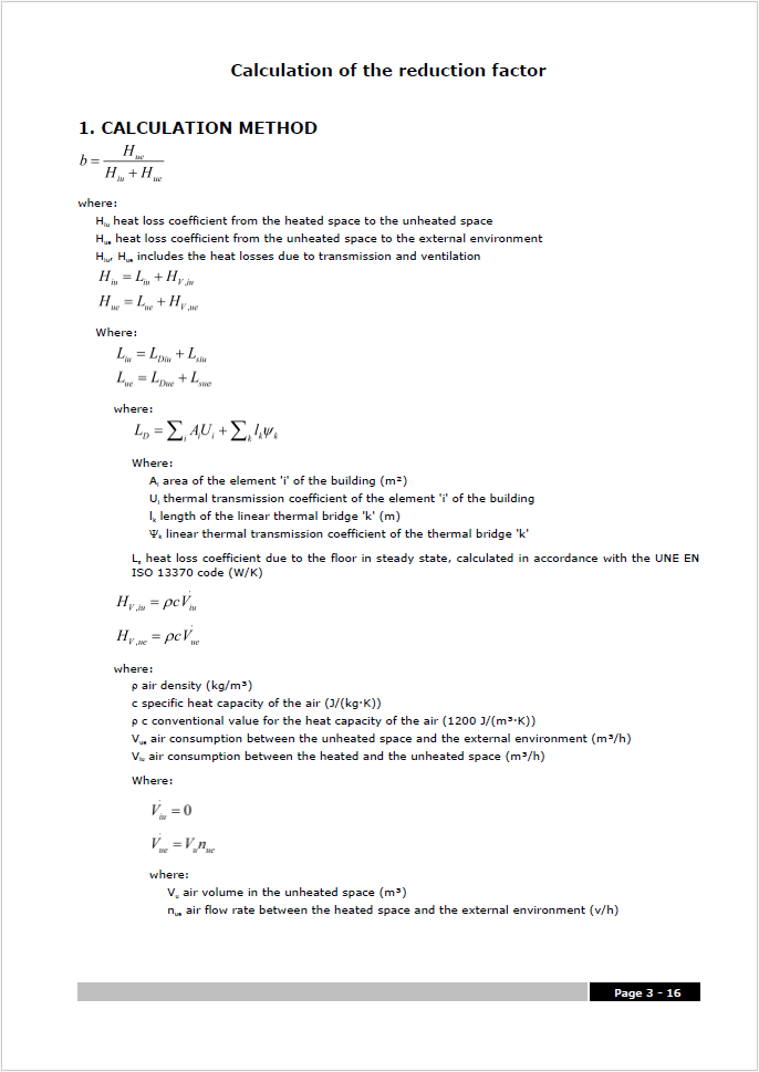
Within the "Complementary reports", we have added the "Calculation of the reduction factor (b)" report, which contains the methodology and detailed results from the calculation of the heat transfer to the unconditioned spaces of the building in accordance with EN ISO 13789:2017.
The results provided in this new report are used in the calculation of the heat transfer coefficient of the building envelope report.
As a result of the simulation, a new file with .csv extension is produced which contains the calculated values of the indoor air temperatures of the zones and the outdoor air temperature, for each hour of the year. These numerical values coincide with those represented graphically in the complementary "Internal comfort" report.
The new temperature results file is available in the _dat directory next to the file containing the job:
… \ […]_dat\Energyplus\Project_cons.res\Zone air temperatures.csv
Arquimedes
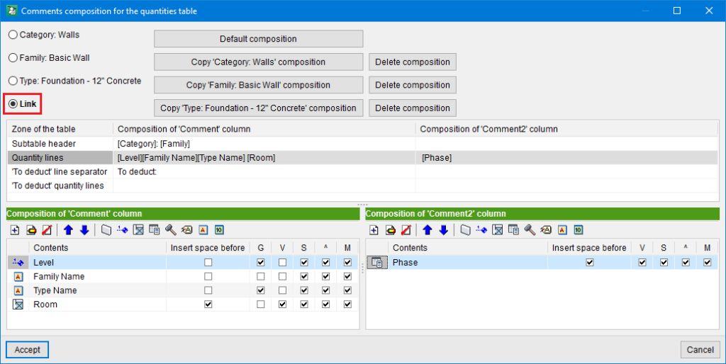
In Arquimedes version 2024.c, the "Link" option has been added to the "Comments composition for the quantities table" dialogue box. This dialogue box is opened by clicking on the edit button with the same name: "Comments composition for the quantities table", which is located next to the combination used for the extracted quantities.
The "Link" option refers to the Entity-Item linkage (assignment between the Revit entity and the Arquimedes item). This linkage has a combination for extracting quantity lines and, among other things, two comment compositions (one for each comment column, "Comment" and "Comment2"). Using the "Link" option, each of these comment compositions can now be customised for the link so that it does not affect any other links.
Entity-Item links are unique. Therefore, if the comments for the link are customised and the "Link" option is activated, this change only affects that link or Entity-Item assignment.
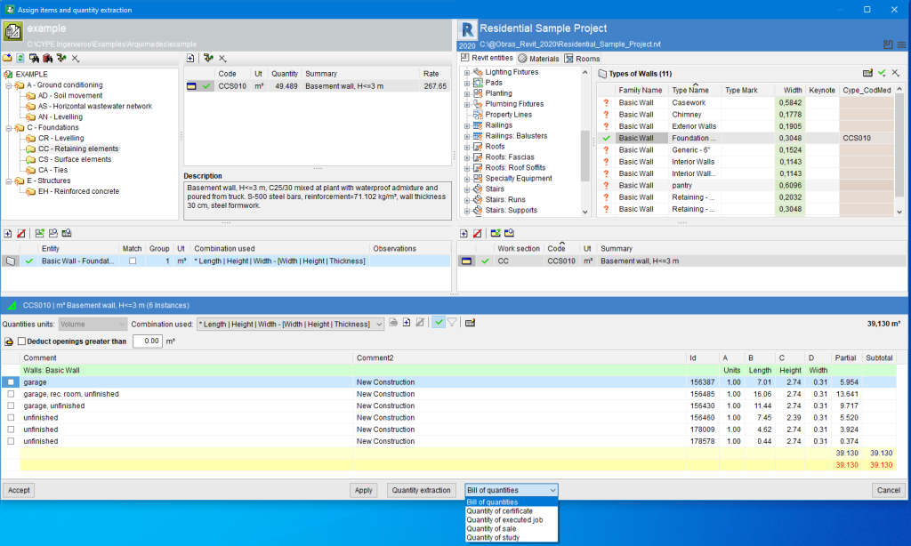
Next to the "Quantity extraction" option, a drop-down menu has been implemented in Arquimedes version 2024.c that allows users to select the type of quantities table to be used for extracting quantities.
If the quantities are to be extracted for a certificate table, it should be noted that quantity extractions are not cumulative, but partial (the contents of the quantities in the "Assign items and quantity extraction" window are always transferred to the quantity tables). Therefore, this table provides a partial quantity in progress and not at source. This means that the certificate has not been closed. The same applies if the quantity is extracted for the completed job table.
Open BIM Quantities
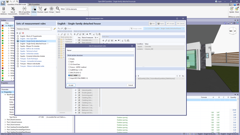
New predefined work section structures have been added for creating a new "Set of measurement rules" (in Open BIM Quantities) or a "Mapping file" (in applications with a "Bill of quantities" tab):
- RICS NRM 1-3
This includes the sections of the New Rules of Measurement (NRM) as defined in volumes “NRM 1: Order of cost estimating and cost planning for capital building works” and “NRM 3: Order of cost estimating and cost planning for building maintenance works”. - DIN 276 2018-12
This includes the cost groups defined in DIN 276 2018-12. - GuBIMClass
System for classifying building elements according to their main function in a BIM environment.
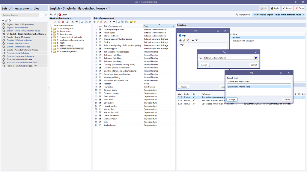
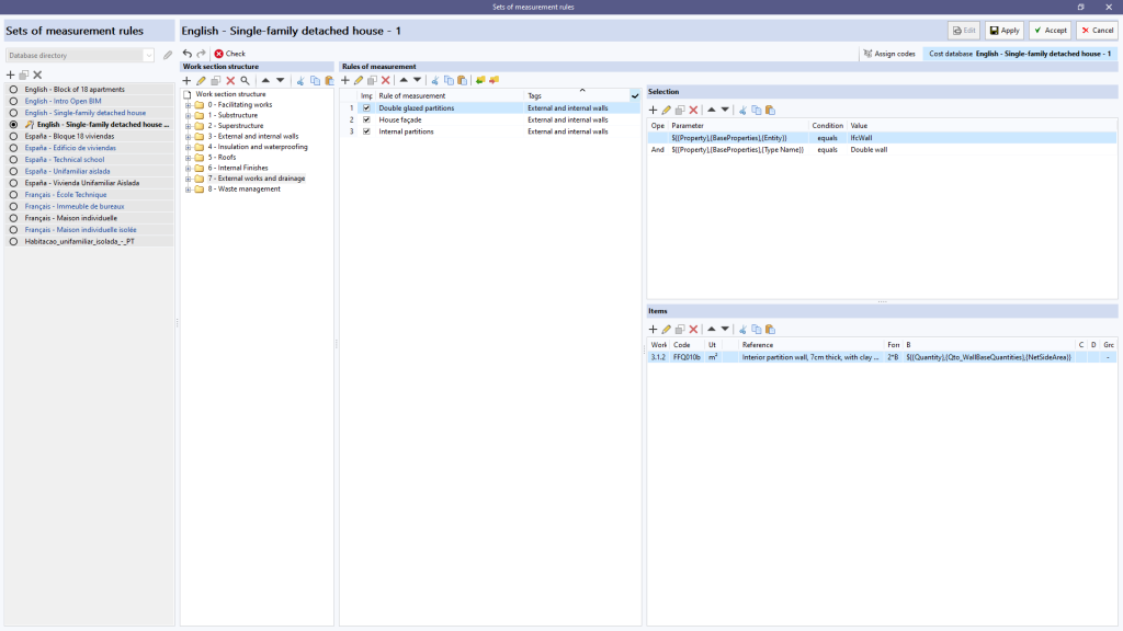
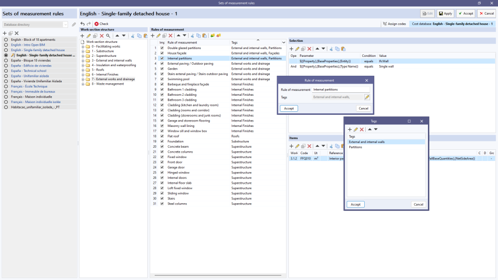
As of version 2024.c, tags can now be associated with the rules of measurement defined within a "Set of measurement rules". When editing the reference of a rule, the "Tags" field now appears, allowing several independent text strings to be inserted. In order to make it easier to enter tags, when adding or modifying a tag, a button appears, with a blue arrow icon, which launches a list of the tags defined so far.
In the list of rules of measurement, a "Tags" column has been added which not only shows the tags linked to each rule but also allows the elements that appear in the list to be filtered. To do this, a button has been added to the column header. Clicking on this button displays a window where a list of tags can be specified. When accepting the window, only the rules that contain the entered tags will be displayed. This makes it easier to manage rules when there are a large number of rules in the project.

