New features common to several programs
Rotating model components with the element selection tool
As of version 2023.g, applications with the "Element selection tool" (this tool was implemented in version 2021.e) can rotate model components about their vertical axis. Pressing the space bar on the keyboard will rotate the selected objects by 90°, from their current position, in an anticlockwise direction.
Applications with a 3D environment. Level management
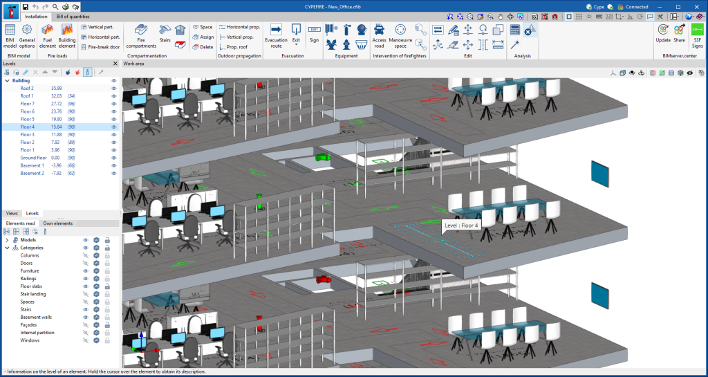
As of version 2023.g, applications with a 3D work environment can include a new feature that allows users to associate the elements of their model with levels (the programs that have this utility in version 2023.g are listed at the end of this new feature). The levels can correspond to the floors of a building or any other reference plan required for the model.
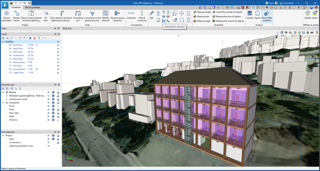
The level management menu is included in the applications by means of a dockable window. In this panel, there is a drop-down list with the buildings and levels defined in the model, as well as the available options (create, edit, delete, assign, etc.).
The options in the "Levels" window allow new buildings and levels to be entered in the model. Levels must be defined within a building. Next to each level, we can see its elevation and, shown in brackets, the number of associated model components. Their visibility in the work area can also be activated or deactivated.
Using the "Assign elements to a level" option, we can select components of the model from the work area and associate them with the level selected in the list. The "Unassign elements to a level" option allows the reverse operation to be carried out. To help users when using these tools, the elements that belong to the selected level will be shown in green and those that belong to another level will be shown in red. The "Information on the level of an element" option is also available, with which it is possible to inspect an object from the work area and obtain its current level. Finally, the "Automatic level assignment" option associates the components of the model to the defined levels automatically. To do this, the geometry of the element is analysed and the level immediately below it is searched for.
When linking to a BIM project, the application can read the buildings and levels of the contributions. These will be listed in the "Levels" window in blue and we can assign model components to them. To avoid congruence issues between contributions, buildings and levels that have been read from the BIM project cannot be edited.
The levels are exported in IFC format via the "IfcBuildingStorey" entity. As this is an entity included in the standard, applications from other manufacturers that work with IFC files can read the levels and their relationship with the components of the model.
In this 2023.g version, the level management window has been included in the following applications:
- CYPEFIRE
- CYPEFIRE Hydraulic Systems
- CYPEHVAC
- CYPELEC Distribution
- CYPELEC Electrical Mechanisms
- CYPELEC PV Systems
- CYPEPLUMBING Water Systems
- Open BIM Analytical Model
- CYPE Lightning
- StruBIM Rebar
Implementing codes
Loads on structures. Wind loads
Implementation. MS 1553:2002, AMD. 1:2013 (wind loads Malaysia)
MS 1553:2002, AMD. 1:2013. Code of practice on wind loading for building structure. AMENDMENT 1
Implemented in CYPECAD.
Loads on structures. Seismic loads
Implementation. REP 2021 (seismic loads Panama)
Reglamento de Diseño Estructural para la República de Panamá – 2021 (REP 2021)
Implemented in CYPECAD and CYPE 3D.
Water supply
Implementation. RENISDA (water supply Bolivia)
"Reglamento nacional de instalaciones sanitarias domiciliarias (RENISDA)".
- "Instalaciones domiciliarias de agua potable".
Implemented in CYPEPLUMBING Water Systems.
Water evacuation
Implementation. RENISDA (water evacuation Bolivia)
"Reglamento nacional de instalaciones sanitarias domiciliarias (RENISDA)".
- "Instalaciones domiciliarias de evacuación de aguas residuales".
- "Instalaciones domiciliarias de drenaje pluvial".
Implemented in CYPEPLUMBING Sanitary Systems.
Open BIM Site
New WMS services for obtaining maps
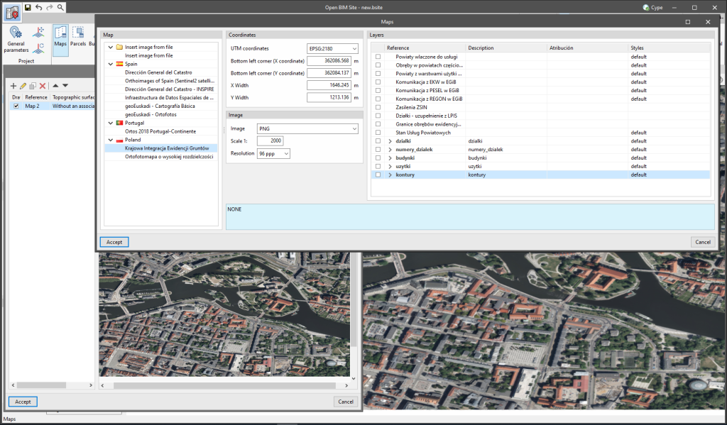
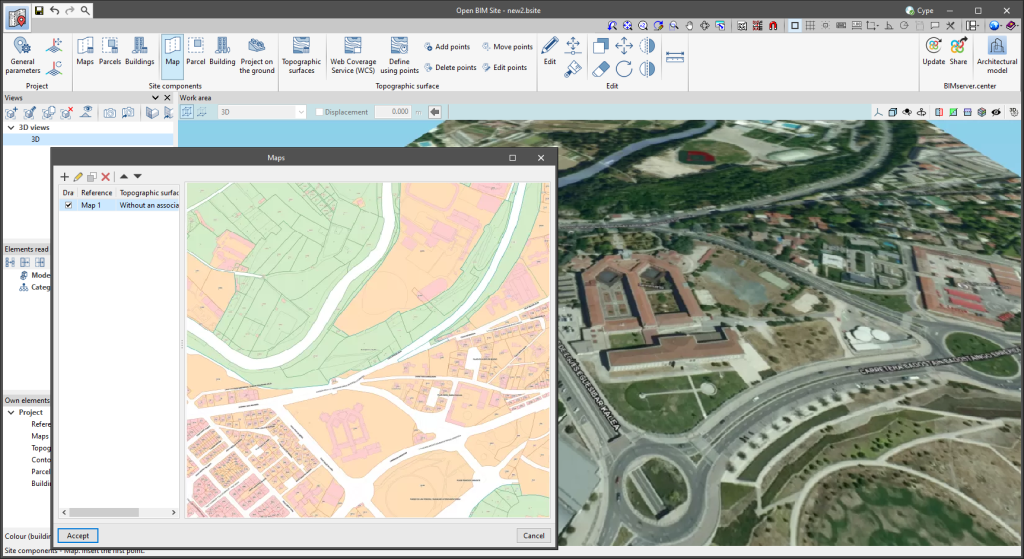
As of version 2023.g, Open BIM Site allows users to obtain maps via WMS services from the following data sources:
- Spain
- Infraestructura de Datos Espaciales de Navarra
- geoEuskadi – Cartografía Básica
- geoEuskadi – Ortofotos
- Poland
- Krajowa Integracja Ewidencji Gruntów
- Ortofotomapa o wysokiej rozdzielczości
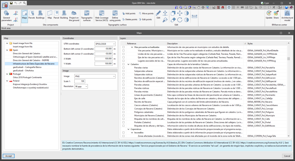
Improved map configuration window
The following changes have been made to the map configuration window:
- The options available in the configuration window for maps from WMS services can now be obtained from the description of the service itself. This is done via the "GetCapabilities" request defined in the OpenGIS specification for WMS.
- The sources are located in the left sidebar of the window and organised in a tree. This makes it easier to identify the WMS services associated with each country.
- In the UTM coordinate selection of the WMS services, all reference systems are displayed in EPSG code.
- The layers available in the WMS services are now displayed in a tree structure according to the service description. They also include the "Description", "Attribution" and "Styles" columns.
CYPECAD
Improvements and corrections
CYPECAD version 2023.g includes the following program improvements and corrections for some specific cases:
- An option has been implemented that allows the check for the minimum bending resistance of columns to be omitted from the capacity design for Eurocode 2 and its National Annexes. Using this option, Eurocode 8 paragraph 5.2.3.3(2) can be considered where columns are exempt from the check in the circumstances described in this article.
- An error in the design of beams with stirrup-carrying reinforcement that occurred in some particular cases and with beams of small widths has been corrected.
- The article description has been corrected in the check of the number of bars for columns, according to the design criteria for ductility of Eurocode 8.
- A one-off error in the maximum reinforcement ratio check according to Eurocode 8 seismic design criteria has been corrected.
- An error in the checking of stirrup spacing outside the critical zone in columns for NSR 10 (Colombia) has been corrected.
- An error in the wet service factor in the timber checks for CIRSOC 601 (Argentina) has been corrected.
- Beam design has been improved, prioritising complete stirrups rather than overlapping stirrups in the event of torsion.
- The modification to clause 6.4.5, Punching shear resistance of slabs and column bases with shear reinforcement, of EN 1992-1-1:2004/A1:2014 has been implemented.
- An error in the load combinations used for designing foundations as a reinforced concrete element, which occurred when selecting the Spanish structural code "Código structural" and the criteria for foundations from the Spanish building code CTE DB SE C, has been corrected.
- The checking of deflection in contour plots has been improved. When selecting "Worst case combination", instead of showing the contour plots of the selected combination, those of the self-weight loads were shown, although the analysis of the deflection was carried out correctly. Now, the values corresponding to the selected combination are displayed.
- The checking of the fire resistance of columns has been improved. If a column span crosses several floors, the check is carried out with the values entered in the floor above. Previously, in some of these cases, no such check was carried out.
- An error that could occur in "General data" when editing "Criteria of reinforcement by ductility" or "Building elements" when changing the seismic code has been corrected.
- An error that occurred when changing the section of a column from rectangular to circular, or vice versa, on the first floor using the column reinforcement editor, has been fixed.
- The export of columns to IFC has been improved. The angle at which it has been defined is now included.
- The "Forces in flat/waffle slab nodes" panel has been improved. Now the whole tables are displayed without the need to scroll horizontally.
- The display of curved stair floor slabs in 3D views has been improved.
- An error that occurred during foundation design when there were loads on a foundation element whose associated load case was deactivated has been fixed.
- The editing of portal frames has been improved. Users can now use "Undo" and "Redo" after modifying "Deflection groups".
- An error that occurred when editing a tendon with an end that was very close to but not intersecting another tendon has been fixed.
- The export of floor slab reinforcement has been improved. Some floor slabs were not using the covers defined for them.
- The installation of example jobs has been improved. If no example jobs are available in the installation language, the example jobs available in English are installed.
- The design of columns for buildings with low ductility reinforcement criteria has been improved, based on what is specified in the Portuguese National Annex NP EN-1998-1:2010 / A1 2013 concerning point 4.4.1. When considering the low ductility criteria, the check of the "Global and local ductility conditions (NP EN-1998-1:2010, 4.4.2.3)" is no longer considered.
CYPE Connect / StruBIM Steel
StruBIM Steel
Improved connection creation
Up until StruBIM Steel version 2023.g, StruBIM Steel's "Connection" tool allowed a connection to be created from a selection of bars.
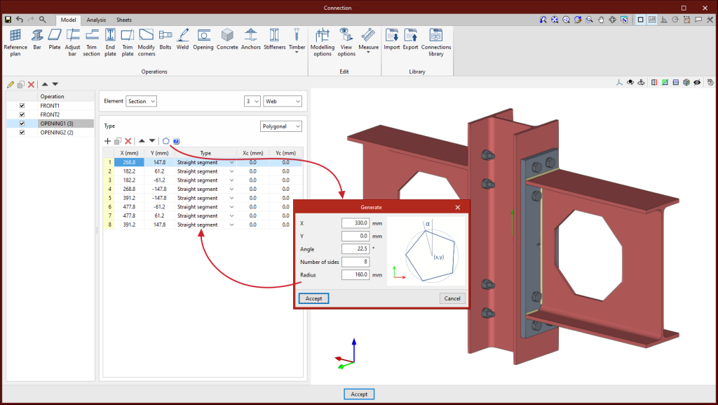
As of version 2023.g, a connection can now also be selected as a pattern. After selecting the connection pattern, another group of bars can be selected to apply the same connection and, in addition, to group them together. To do this, with the bars selected, simply right-click to apply the connection pattern. This operation can even be repeated on another group of bars to apply the same connection again.
Improved accessory creation
Up until StruBIM Steel version 2023.g, the "Accessories" tool allowed an accessory to be added to a bar by selecting an intermediate position on its axis.
As of version 2023.g, an accessory can also be selected as a pattern. After selecting the accessory pattern, users can select other points at which to apply the same accessory. If possible, the entered accessories will be grouped from the same pattern.
Update of displacements from the BIM project
Up until version 2023.g, the update of bars from the BIM project updated both the bar section as well as the displacements, rotation and position.
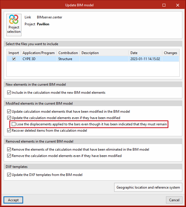
As of version 2023.g, the displacements and rotation can be maintained in the BIM project update.
The bars generated from the BIM project include the "Keep the displacements applied to the bars if the design model is reloaded" option in the "Insertion point" section. When this option is deactivated, all the parameters of the bars are updated. When the option is activated, the level parameters are not updated. This option will be deactivated by default, allowing updates to be carried out. When a bar is assigned a level, the option is automatically activated.
Improved "Join" y "Divide" bars
As of StruBIM Steel version 2023.g, after dividing or joining bars, the connections that were defined for those bars will remain, if and when possible.
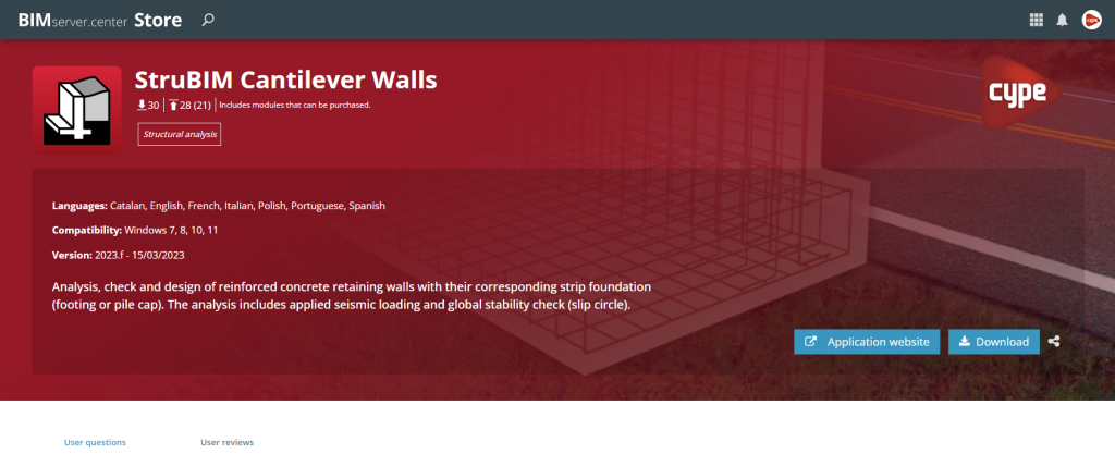
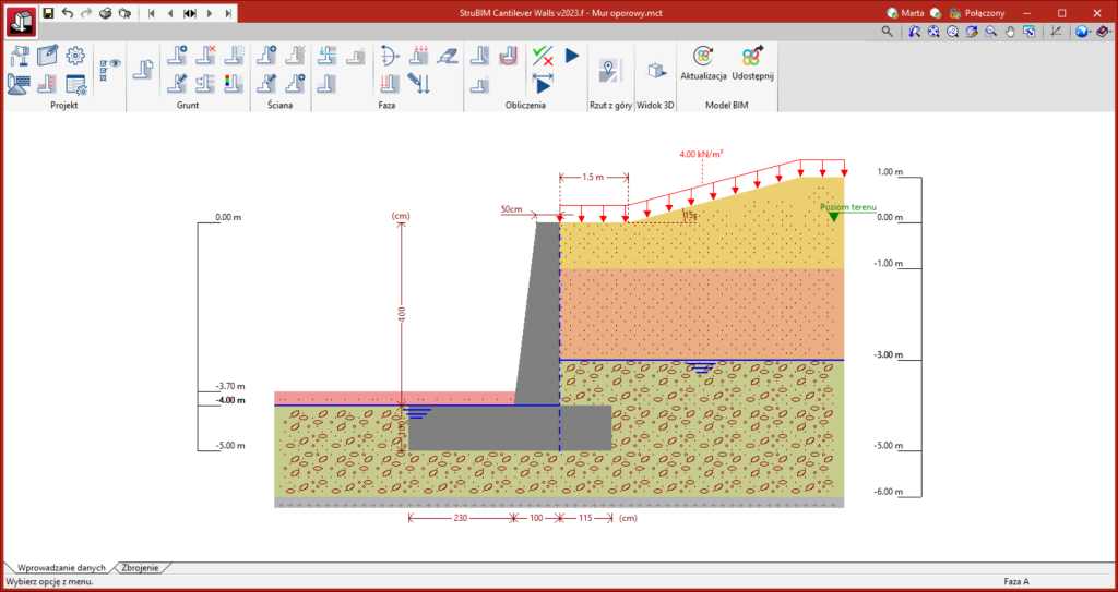
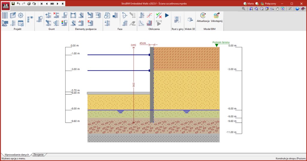
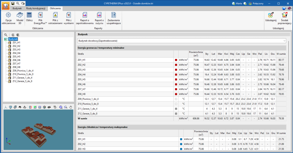
StruBIM Cantilever Walls / StruBIM Embedded Walls / CYPETHERM EPlus
Installation in Polish
From 15 February 2023, downloads of the StruBIM Cantilever Walls and StruBIM Embedded Walls applications (versions 2023.f onwards) from the BIMserver.center platform, can now be installed in Polish. Installation in Polish is also available for CYPETHERM EPlus for downloads from BIMserver.center on or after 21 March (versions 2023.f onwards).
StruBIM Rebar
New editing tools
Within the "Edit" group of the application toolbar, the following options have been added to modify the geometry of the grounding conductors:
- Add points
Allows new vertices to be added to the polyline describing the geometry of the conductors. - Delete points
Allows vertices to be deleted in the polyline describing the geometry of the conductors. - Join
Allows two conductors to be joined together. The reference of the unified conductor will be the one corresponding to the first conductor selected in the operation. - Divide
Allows a conductor to be divided into two conductors. The reference of both conductors will be the one corresponding to the original conductor. - Extend/trim element
Allows a conductor to be extended or trimmed to the outline or projection of another conductor. First, select the element to be used as an outline and then the conductor to be modified. If the second conductor extends beyond the contour, the clicked segment will remain. - Extend/trim to corner
Allows the ends of two conductors to be extended or trimmed to make a corner. When selecting the second conductor, the part of the element to be retained must be specified.
Composite elements of the IFC model
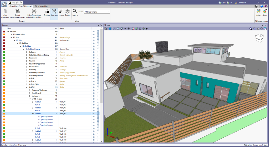
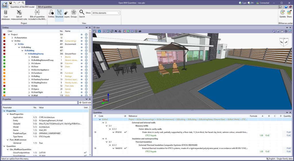
As of version 2023.g, Open BIM Quantities can read and display IFC model elements ("IfcElement") that contain other elements. This feature allows users to explore the relationships between different elements of the model in a more complete and detailed way.
When using the "View" mode by "Structure", components that are part of an element can be seen in the "Entities" tree. Examples of such a situation are walls ("IfcWall") and the relationship with their openings ("IfcOpeningElement"), as well as the subordinate parts of a building element ("IfcBuildingElementPart") and their relationship with the main component.
Computable built areas
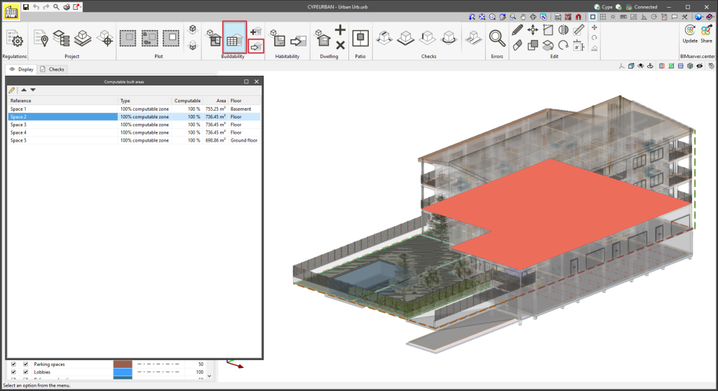
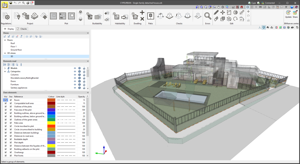
CYPEURBAN version 2023.g includes new tools regarding computable built areas:
- New check for computable built areas according to use
Check the maximum built area, computable in square metres, according to the different uses of the building. The tool allows IFCSpace to be imported and mapped to the different uses of the building. - Computable built area table
The table shows all the computable built areas of the job and allows users to browse through them while they are highlighted in the 3D model. The table allows the surfaces to be sorted according to computation, use or storey. - Assign properties of computable built areas
Allows users to change the properties of the computable built areas: computation and use.
New patio checks
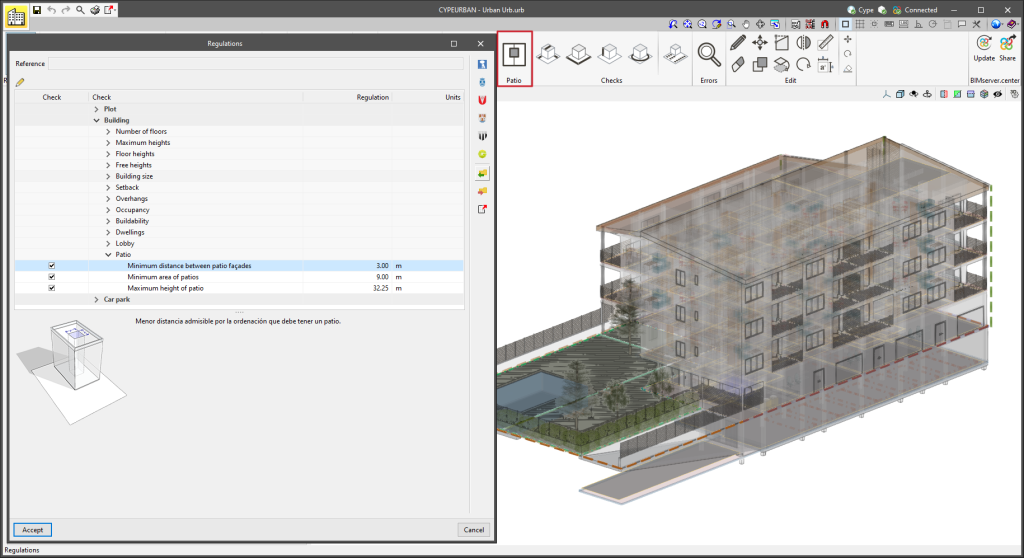
In CYPEURBAN version 2023.g, the following checks have been implemented for patios:
- Minimum area of patios
Smallest surface area allowed for the layout of a patio. - Minimum distance between patio façades
Smallest allowable distance between the façades of a patio due to the layout of the patio. - Maximum height of patio
Highest admissible height for the layout of a patio.
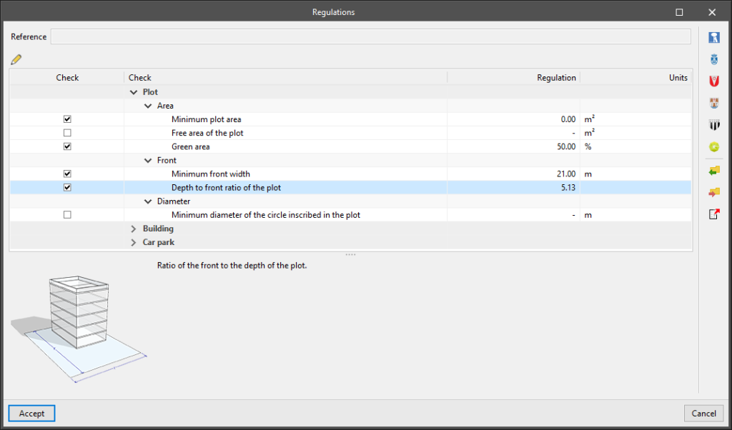
Free area of the plot
In CYPEURBAN version 2023.g, users can define the smallest permissible free surface area that the plot must have. The free plot areas can be imported from other programs via the "IFCSpace" entity by mapping.
CYPEPLUMBING Sanitary Systems
CYPEFIRE Hydraulic Systems
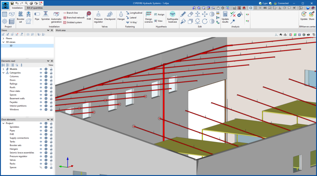
New 3D work environment
CYPEFIRE Hydraulic Systems has upgraded from a 2D work environment to a new 3D work environment.
Thanks to the new 3D working environment, users can achieve the following:
- Greater geometric precision when placing pipes, sprinklers, hangers, valves, etc.
- All elements and pipes in the different views (3D views, plan views, elevation views, etc.), mainly vertical pipes, are now easier to generate.
- Greater geometrical precision when placing and checking the elements of the system.
This new version of CYPEFIRE Hydraulic Systems allows any jobs carried out with previous versions of the program to be read and analysed.
The program's edit menu has also been updated. The default receiver is now the select receiver and not the edit receiver.
Two new tools have also been added to the editing menu:
- Extend/trim element
- Extend/trim to intersection
Design scenarios
CYPEFIRE Hydraulic Systems version 2023.g allows different design scenarios to be generated and analysed simultaneously.
With this feature, the program is much more versatile. For example, sprinkler installations can now be analysed by simulating the most unfavourable and the most favourable area at the same time and the most unfavourable area can also be determined by entering different operating areas.
When designing the pipes of the installation, users must select the scenarios to be used by the program to determine the appropriate size.
CYPEHVAC Hydronics
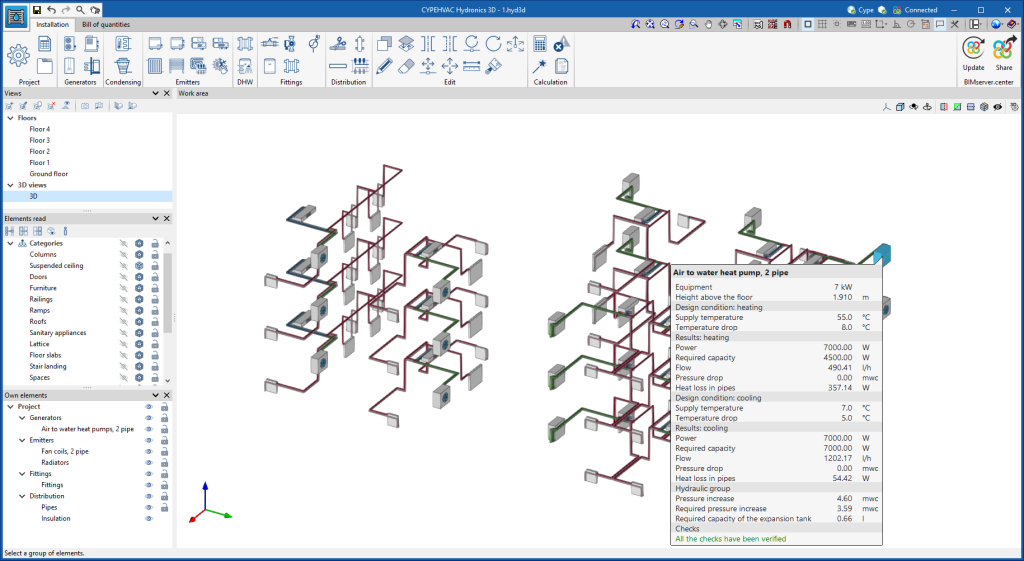
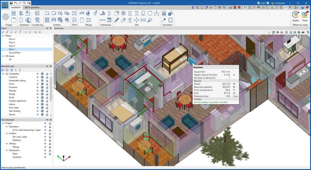
New 3D work environment
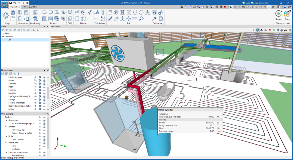
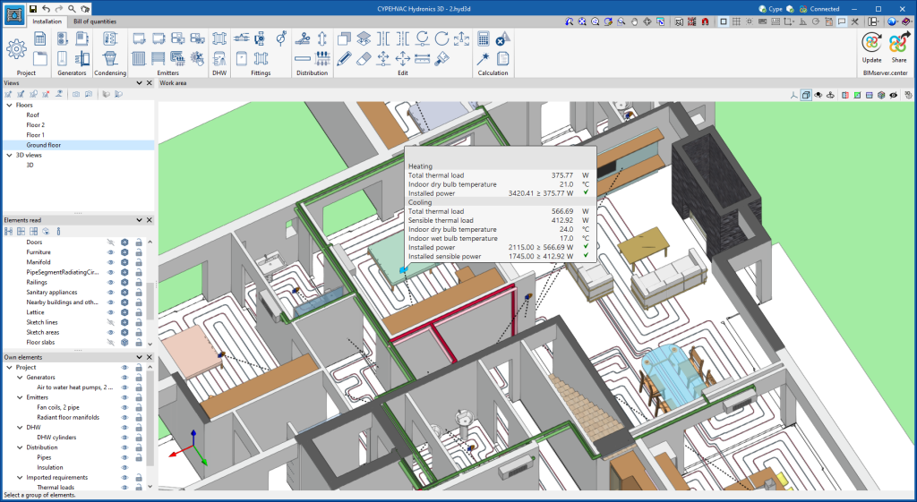
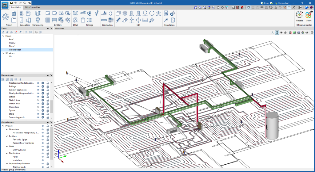
CYPEHVAC has moved from a 2D environment to a new 3D work environment, providing greater capacity in the modelling of water distribution systems for HVAC systems.
With the new 3D work environment, the following can be achieved:
- All elements and pipes can now be entered in the different views (3D views, plan views, elevation views, etc.). Vertical pipes in particular are now easier to generate.
- Greater geometric precision when positioning the elements of the system.
New equipment
The new version of CYPEHVAC also includes the new feature of being able to analyse elements of the system that were not available in previous versions, such as the distribution elements, the condensation circuit equipment and the elements that link the air-conditioning system with the DHW system.
Some of the existing equipment in previous versions, such as heat pumps and fan coils, has been split into types for easier use. For example, fan coils have been split into 2-pipe and 4-pipe fan coils. Furthermore, air handling units have been explicitly added.
Separating hydraulic circuits
Distribution elements such as manifolds, hydraulic separators and heat exchangers have been added, which allow the system to be divided into separate circuits. The program calculates the pressure losses in each of these circuits separately and, in the case of circuits separated by a heat exchanger, it also calculates the volume of water in each circuit.
Water condensation circuit
The design of condensing circuits for water-to-water heat pumps has been integrated. Based on their power and performance data, the program analyses the thermal power in the heat pumps' external heat exchanger and allows the hydraulic circuit to be defined up to the equipment responsible for dissipating this power. For this purpose, cooling towers as well as the generating equipment representing a heat source, e.g. a geothermal collector system, can be provided.
BIM integration
The program allows users to import the requirements of the radiant floor systems, as well as the thermal loads of the building, so they can be assigned to the equipment to be designed.
Previous versions
The implementation of the 3D work environment, together with other new features included in this update, means that version 2023.g of the program and later versions will not be able to read any jobs created with versions before 2023.g. These jobs can be read with version 2023.f or with the version with which they were created.
Previous versions of CYPEHVAC can be downloaded from the BIMserver.center platform. However, we recommend that the latest version is always used for new jobs.
Open BIM Quantities
Status bar
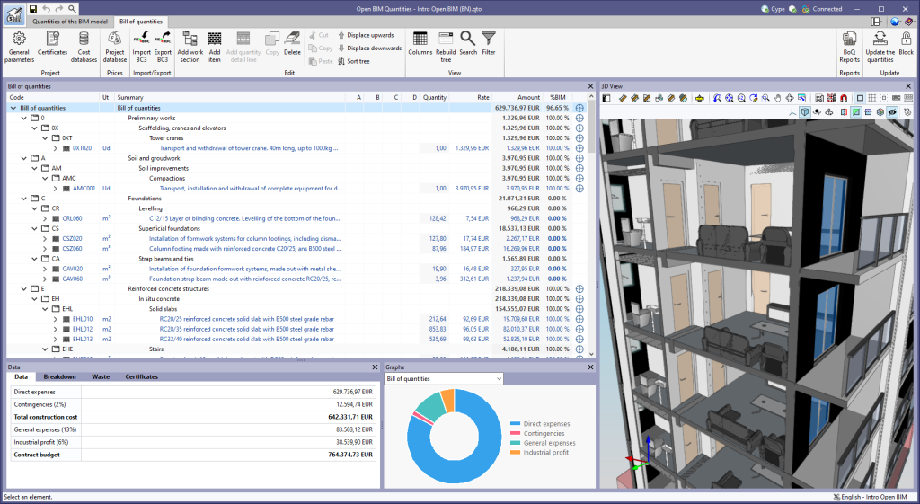
A status bar has been included at the bottom of the main window. As well as displaying contextual information about what is being carried out in the application, the status bar indicates the reference of the active set of measurement rules. This reference can also be displayed in the status bar of the "Bill of quantities" tab.
Applications with a "Bill of quantities" tab
Improved filter options
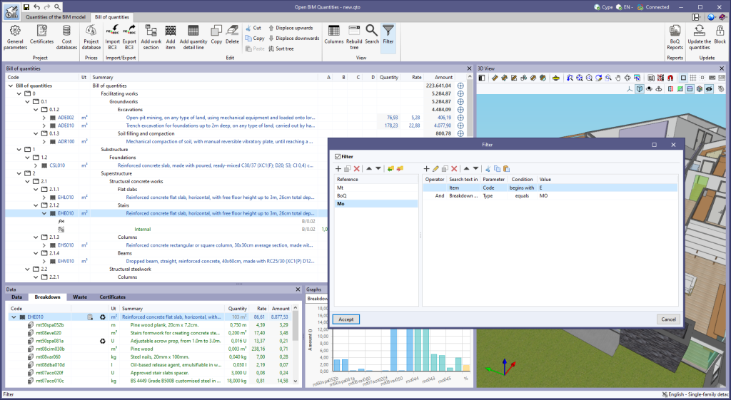
The following improvements have been made to the "Filter" option, available in the "View" group of the toolbar:
- A list of filters can now be defined for the project. The selected element will be the one to be applied to the bill of quantities.
- The "Filter" option has been added to the editing window of the "Project database" or a "Cost database".
- Filters can be exported as a file (".bib767") to be used in multiple projects.
- In the list of conditions of a filter, the "Cut", "Copy" and "Paste" tools have been added. These allow conditions to be moved or copied from one filter to another.
- The "Search text in" and "Parameter" fields have been added to the window for inserting a condition within a filter. This way, the program now allows users to filter by parameters other than the "tag" of the "quantity detail lines", as was the case up to now. In this version, the following options are available for these fields:
- Search text in: Item
- Parameter: Code
- Parameter: Summary
- Parameter: Type
- Parameter: Key terms
- Parameter: Amount
- Search text in: Breakdown concept
- Parameter: Code
- Parameter: Summary
- Parameter: Type
- Parameter: Key terms
- Search text in: Quantity detail line
- Parameter: Tags
- Search text in: Item
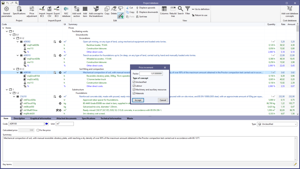
Price increment
The "Price increment" option has been added to the editing window of the "Project database" or a "Cost database. With this tool, the prices of the concepts contained in the database can now be adjusted according to a "Factor". Furthermore, the application allows users to indicate the nature of the concepts ("Unclassified", "Labour", "Machinery and auxiliary resources" and "Materials") on which the operation is to be applied.
"Breakdown" tab in work sections
The "Breakdown" tab has been included in the "Data" window for the work sections of the bill of quantities. In previous versions, the "Breakdown" tab was only available for the items, where a table with their breakdown into resources is shown.
Now, the work sub-sections or items that are part of a work section can be displayed in this table.
Graphical representation
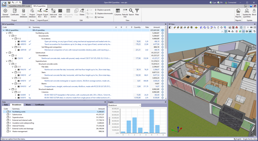
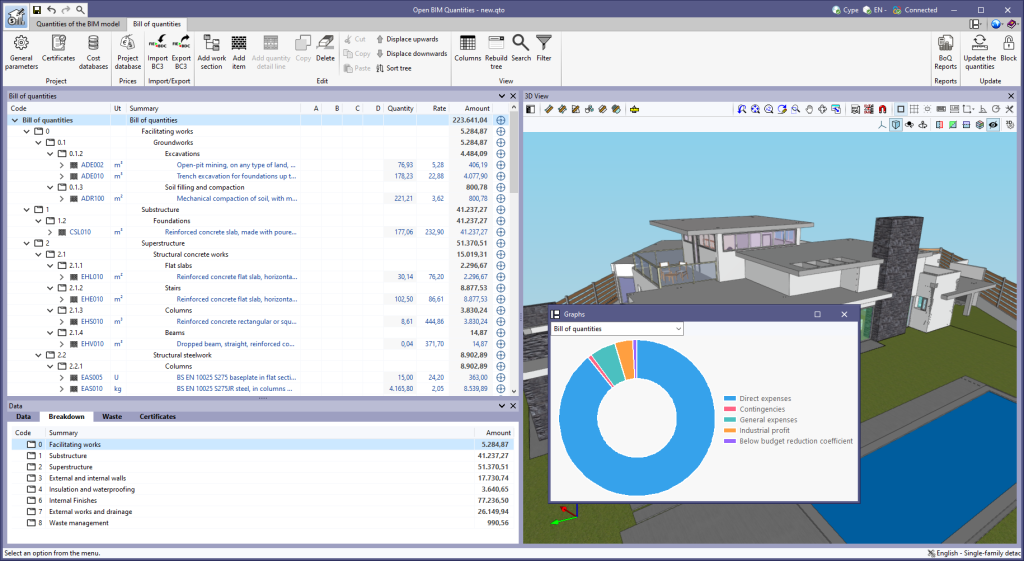
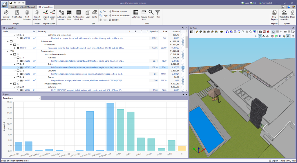
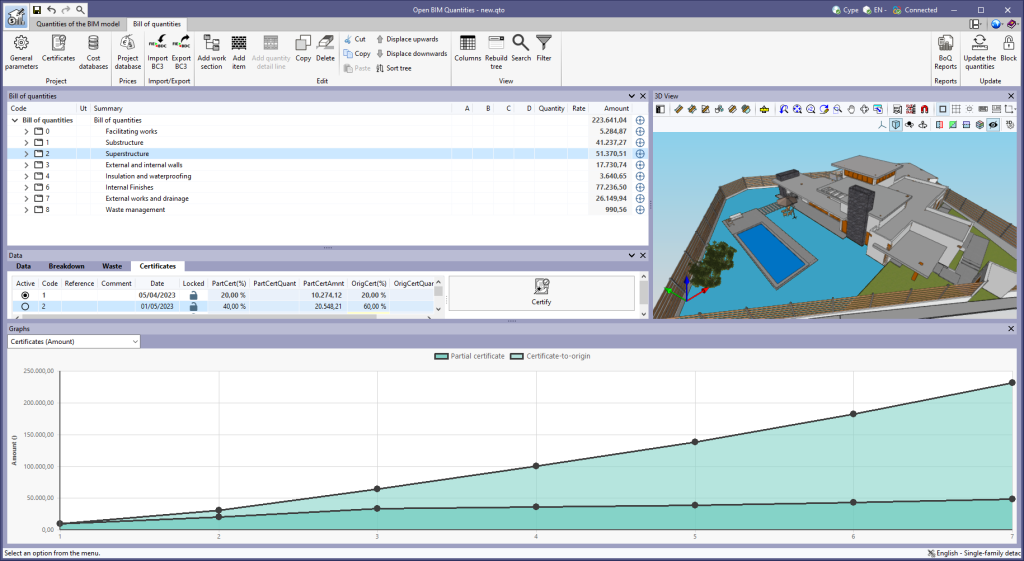
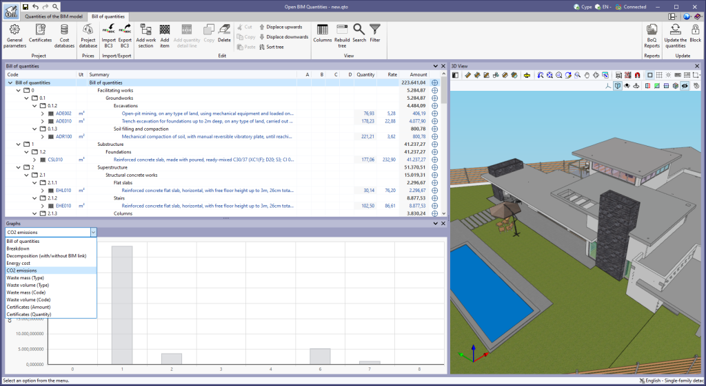
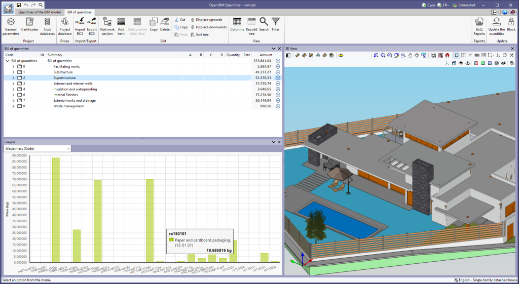
As of version 2023.g, the bill of quantities data can now be displayed graphically. For this purpose, the "Graphs" window has been added to the "Bill of quantities" tab. This window contains a drop-down list for selecting the graph to be displayed. In this version, the graphical representations (columns, circles, lines, etc.) of the following concepts are available:
- Bill of quantities
- Breakdown
- Breakdown (with/without BIM link)
- Energy cost
- CO2 emissions
- Waste mass (Type)
- Waste volume (Type)
- Waste mass (Code)
- Waste volume (Code)
- Certificates (Amount)
- Certificates (Quantity)
The graph generated depends on the component of the bill of quantities table that has been selected. It is important to note that the available graphs depend on the type of element (work section, item or quantity detail line). By hovering the cursor over a section of the graph, a box will appear with the parameter reference and its value, allowing users to have a better understanding of the data shown.
Graphs with a key allow data sets to be hidden by left-clicking on their reference. When a set is not visible, its reference is crossed out and can be reactivated by clicking on it.
CYPEURBAN
Sorted regulation according to the type of check
The "Regulations" section has been sorted according to the type of check. The checks have been grouped under the following headings:
- Plot
Area, front and diameter - Building
Number of floors, maximum heights, floor heights, free heights, building size, setback, overhangs, occupancy, buildability, dwellings, lobby and patio. - Car park
Number of spaces, area, dimensions and heights.

