
Work environment
The program is structured in two tabs, "Structure" and "Foundations", accessible from the bottom left of the general interface.
Each of them has an interface with a ribbon at the top that makes it easier to access the different tools in the program. The options visible in the ribbon depend on which tab is open.
"Structure" tab
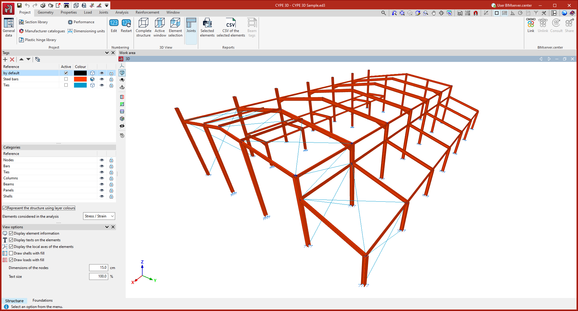
In the first tab, "Structure", the design and analysis of the structure is carried out.
Tabs and ribbon
The tabs available for the "Structure" tab are located at the top of the interface and contain the following tools in the ribbon:
- "Work" tab
Contains the work configuration options, element numbering, 3D view display and obtaining reports. - "Geometry" tab
Contains the options for defining drawings and entering nodes, bars and shells, as well as the tools for editing and importing .dxf or .dwg files and text files. - "Properties" tab
Contains the options for defining diaphragms and editing the properties of nodes (links and ligatures), bars (such as bends, joints and arrow groups) and sheets. - "Load" tab
Contains the options for displaying, entering and editing loads on nodes, bars, shells and panels, as well as surface loads. - "Connections" tab
Contains the options related to the analysis and editing of connections. - "Design" tab
Contains the options related to the design of the job, including stress/strain design and advanced buckling and vibration analyses. - "Reinforcement" tab
Contains the options for consulting and editing reinforcement of concrete columns and beams. This tab only appears if these elements have been defined. - "Window" tab
Contains the options for creating and managing windows in the work area.
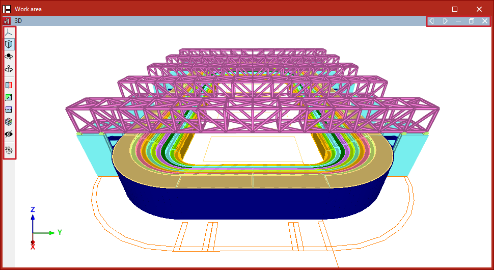
Work area
In the central part of the interface is the "Work area", where the elements of the structure in space are entered and edited and the data obtained after the analysis is consulted. This window can be used to move the frame, orbit and zoom in a fully three-dimensional working environment.
Several windows can be configured and maintained to work with different visualisations of the model, including 3D and 2D views, as well as views of the whole structure or a part of it.
Side panel
The side panel on the left gathers the tools to manage the "Tags" assigned to the elements of the model, to activate or deactivate the visibility and capture of the "Categories" of elements or to control the "Display options".
Additional toolbars
At the top of the ribbon, on the left, there is access to the "File" menu, as well as a toolbar with additional utilities such as saving, "Undo" and "Redo" or the printing of "Reports" and "Drawings". In addition, it is possible to configure and provide shortcuts to the options desired by the user.
At the top right, the program includes various tools such as those related to the management of templates and snaps or access to the "Help" with the documents available for the program.
| Note: |
|---|
| The work area of the main part and the panels on the side are dockable windows that can be freely moved and fixed according to the configuration desired by the user. |
"Foundation" tab
In the second tab, "Foundation", the design and analysis of the foundation elements is carried out. For this purpose, the program automatically takes the results obtained in the analysis of the structure in the first tab.
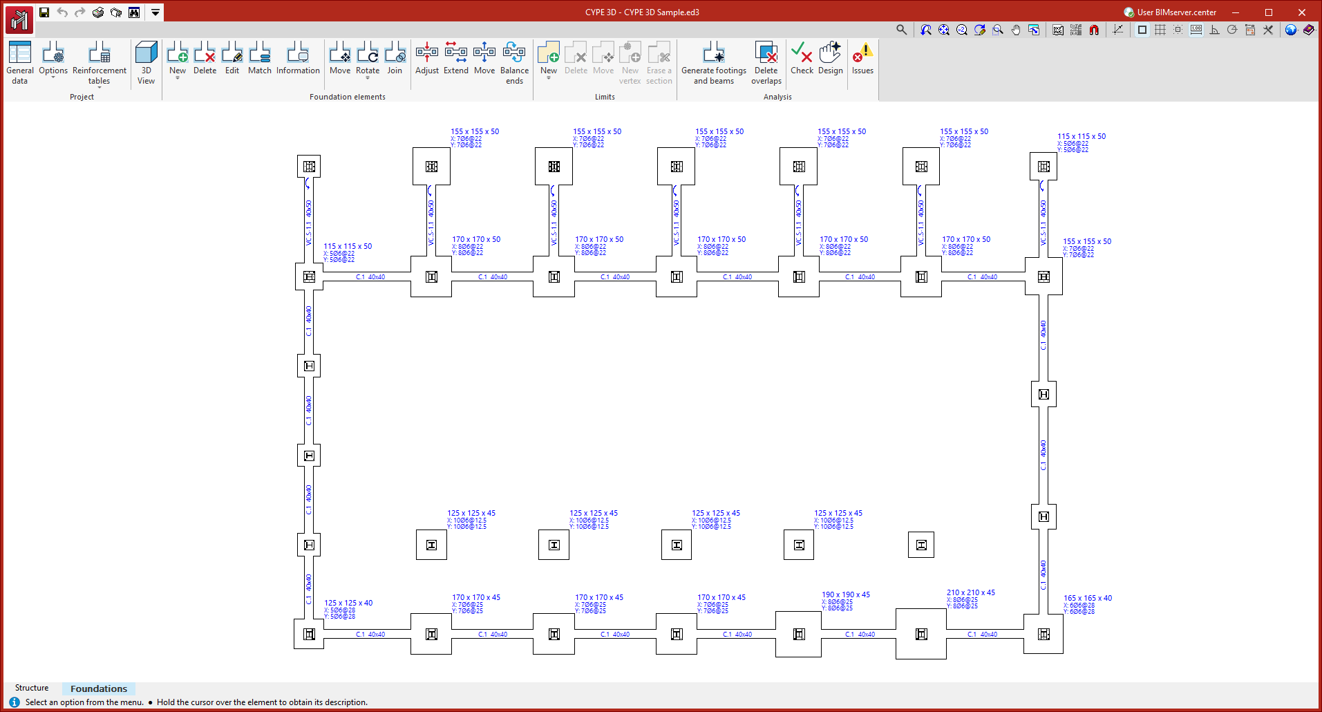
Ribbon
The interface of the "Foundation" tab also includes a ribbon at the top.
This ribbon contains groups with options for managing the "Project" data, entering the "Foundation elements" and defining their "Limits".
Once entered, the analysis of the foundation can be carried out from the options in the "Analysis" group.
Work area
The central part of the interface shows the work area and visualisation area of the foundation, where the elements it contains are entered. In this case, it is a plan view.
Additional toolbars
The program also offers access in this tab to toolbars with tools added to the upper left and right corners.
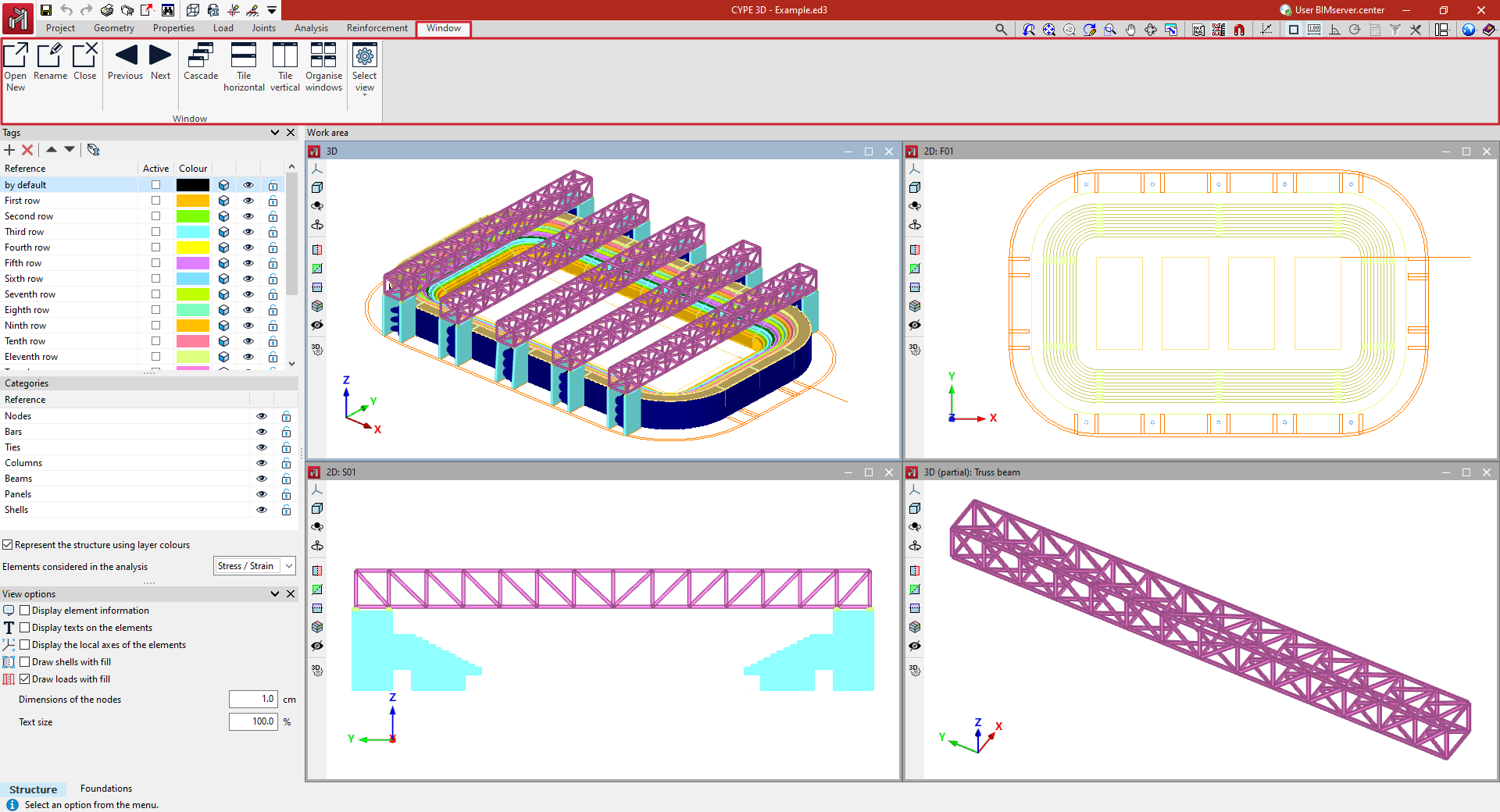
Window configuration
The program can be used to define different windows for viewing the model in the "Work area", either 3D or 2D, making it easier to work on the structure. The window configuration is carried out with the following options in the upper toolbar, in the "Window" tab (in the "Structure" tab).
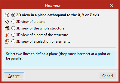
Open new
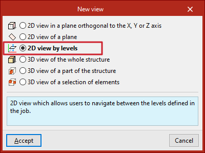
By default, the program generates a window with a 3D view of the entire structure. To create other windows, the "Open new" option is used. This opens the "New view" panel, where different types of views can be selected:
- With "2D view of a plane orthogonal to the X, Y or Z axis" users select two lines that define a plane. These lines must intersect at a point or be parallel. In 2D views, only the elements contained in the plane are displayed.
- From "2D view of a plane" three non-aligned points are selected to define the plane. This option can be useful to create the visualisation of a certain portal frame, a facade plane or a roof skirt.
- By using "3D view of the whole structure", a new three-dimensional visualisation of the whole model is created.
- It is also possible to create a "3D view of a part of the structure". In this case, two points are selected to define the diagonal of the envelope volume of the part of the structure to be displayed in the view. These points cannot be contained in a plane perpendicular to one of the Cartesian axes.
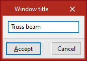
- Finally, to create a "3D view of a selection of elements", the elements to be displayed in the view are selected with the left button and confirmed with the right button. The elements created in this view will also be visible in this view.
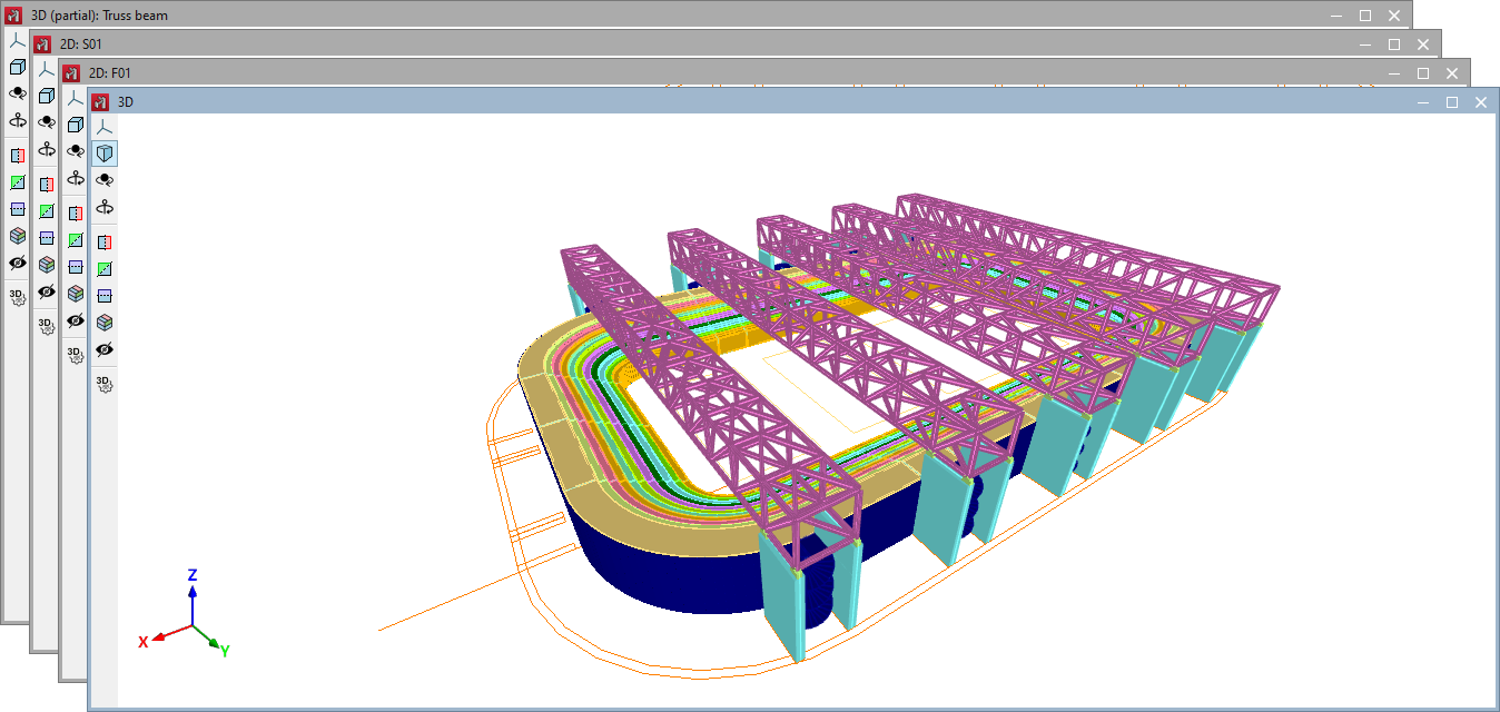
After selecting the required elements, the "Window title" is entered. When clicking "Accept", the window will open showing the 2D or 3D view of the model.
The active window is shown in blue, and the rest in grey.
In the "Work area", each window can be moved or rescaled according to the user's interests and, using the options in the upper right corner, it can be minimised, restored, maximised or closed. If the window is maximised, the program also offers options to switch to the previous or next window.
In addition, on the left-hand side, each window has a series of tools for controlling the visibility of the 3D model, allowing operations such as modifying the projection, rotating the view or creating sections of the model.
| Note: |
|---|
| More information on these tools can be found at the following link. |
Rename
The "Rename" option is used to change the title of the active window.
Close
The "Close" option is used to delete the active window. Another option is to use the cross in the upper right corner of the window in the "Work area".
Previous/Next
The "Previous" and "Next" options are used to switch between windows according to the order of the list of windows.
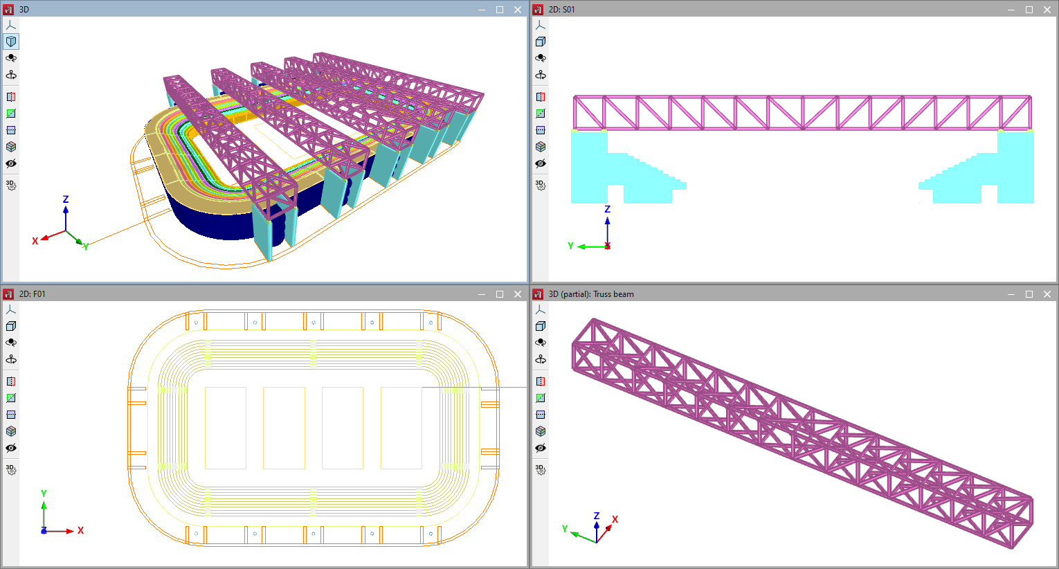
Cascade
Windows can be automatically sorted as "Cascaded" using this option.
Tile horizontal/Tile vertical
These options can be used to arrange the windows automatically in "Tile horizontal" or "Tile vertical".
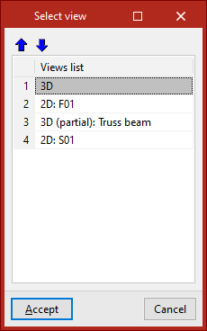
Sort windows
The "Sort windows" option is used to change the order of the list of windows using the tools available at the top of the dialogue box.
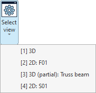
Select window
The "Select window" menu lists the windows available in the project.
For each window, a number is shown in square brackets, indicating the number of the window, together with an indication of whether it is a 3D or 2D view and its title.
Any of the windows in the list can be selected to access it.
Elevation views parallel to grid lines
Elevation views are 2D views that show the elements belonging to the elevation, as well as those arriving at or departing from it. Elements added in the elevation views will be contained within the view plane.
Creating elevation views
If a grid is defined in the model from the "Geometry" tab, the program will allow the creation of elevation views.
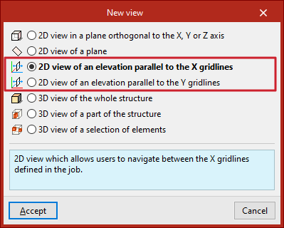
To do this, from the "Window" tab, select the "Open new" option.
Here, you can create a "2D view of an elevation parallel to X gridlines" or a "2D view of an elevation parallel to Y gridlines" and click "Accept".
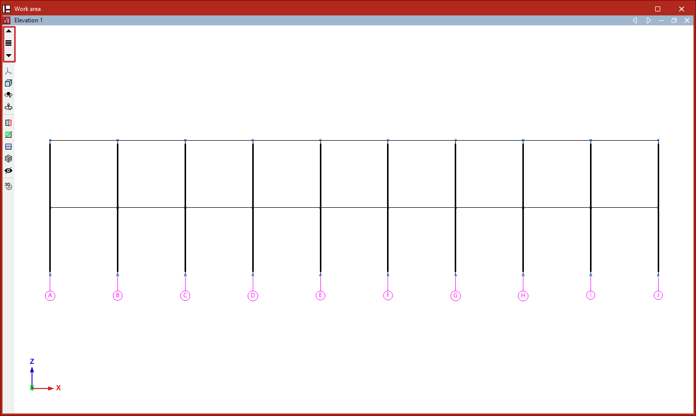
Navigating between elevation views
Once the elevation views have been created, you can move from one elevation to another using the "Move forward one line" or "Move back one line" buttons located on the toolbar on the left-hand side of the window.
You can also click on the "Elevations" option located between these buttons to select and display a specific elevation.
Views by levels
Level views are 2D views that show the elements belonging to each level, as well as those arriving at or departing from it. Elements added in the level views will be contained within the view plane.
Creating views by levels
If levels are defined in the model from the "Geometry" tab, the program will allow the creation of level views. To do this, from the "Window" tab, select "Open new", tick "2D view by levels", and click "Accept".
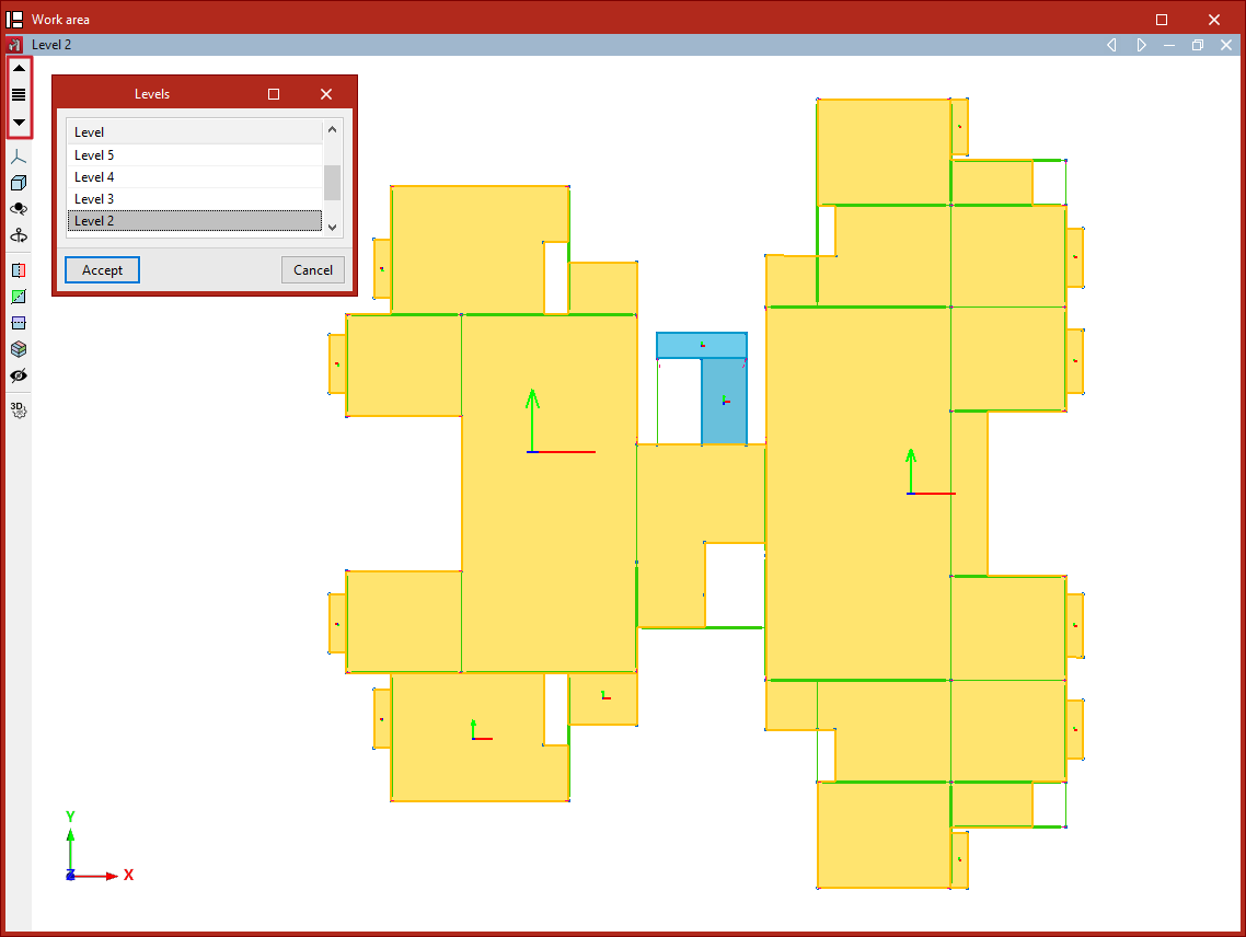
Navigating between level views
Once the level views have been created, you can move from one level view to another using the "Move up one level" or "Move down one level" buttons located on the toolbar on the left-hand side of the window.
You can also click on the "Levels" option to select and display the view of a specific level.
Management of tags, categories and display settings
You can control how model elements are displayed in the workspace using the options available in the various sections of the left-hand side panel of the interface (under the "Structure" tab).
Tags and categories
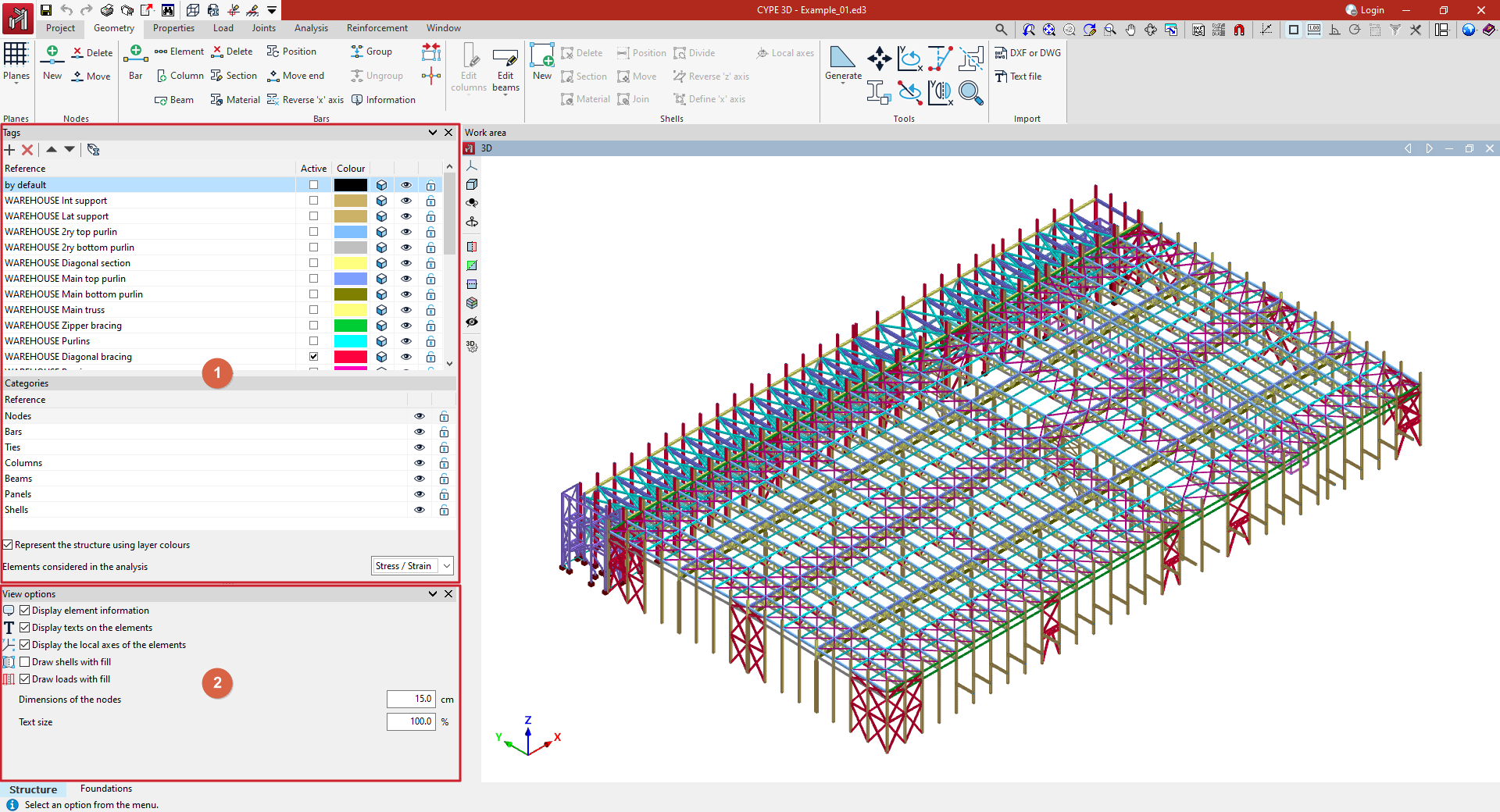
The tag management feature in CYPE 3D allows you to organise and control the display of model elements. To do this, use the "Tags" panel, which is located by default on the left-hand side of the interface (1).
The elements assigned to a particular tag form a layer or group for displaying model elements. By default, the program adds a tag when the project is created. An element can be assigned to more than one tag.
The options at the top of the list allow you to "Add" more tags, "Delete" them and reorder them in the list.
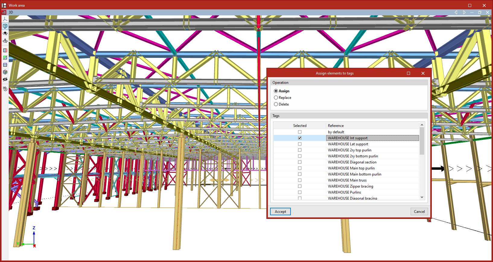
The last option at the top of the list allows you to "Assign items to tags":
- After clicking on the option, you must select the items one by one using the left mouse button or draw a selection box.
- In the "Properties - Selection" panel that appears, you can select the categories of elements you wish to work on. Then, click the right-click button.
- In the pop-up window, you select the type of "Operation" to be performed: either "Assign" items to one or more tags, "Replace" one assignment with another, or "Delete" a specific assignment. Further down, you select the "Tags" to which the items will be assigned, or which will be replaced or deleted, as appropriate.
- Finally, after clicking "Accept", the program will assign the selected items to the selected tags.
The tag list allows the following actions in the different columns:
- The first column displays the "Reference" for each tag, which can be edited.
- Tick the "Active" box to indicate the layer on which you are drawing and to which any elements added to the model will be automatically assigned.
- To change the "Colour" of each tag, click on the coloured cell and select a colour from the available range. If you wish, you can click on "More colours" to define custom colours.
 /
/  The following column allows you to switch between displaying model elements in their realistic form (with their actual dimensions) or as wireframes.
 /
/  It is then indicated whether or not it is visible by selecting the symbol in the next column. You can only interact with the elements of the tabs that are visible.
 /
/  The last column allows you to lock or unlock editing of the items assigned to each tag.
Categories
This section allows you to show or hide elements in the following categories, as well as lock or unlock them, using the options in the columns on the right: "Nodes", "Bars", "Braces", "Columns", "Beams", "Panels" and "Shells".
The checkbox at the bottom allows you to "Display the structure using the layer colours" created in the "Tags" panel.
Using the drop-down menu, you can also choose to display only the "Elements included in the analysis", whether for "Stress/Strain", "Buckling" or "Modal" analysis. Elements not included in the selected analysis will be hidden.
Display options
At the bottom of the side panel (2) are the following additional display options:
- Display element information (optional)
Allows you to enable or disable the tooltip or box displaying information associated with the highlighted item on screen, depending on the selected option. - Display texts on the elements (optional)
Allows you to enable or disable the display of text tags on elements. - Show the local axes of the elements (optional)
Allows you to enable or disable the on-screen display of the local axes for each element in the model. - Draw shells with fill (optional)
Allows you to enable or disable the display of sheet fills. - Draw loads with fill (optional)
Allows you to enable or disable the display of load fills. - Dimensions of the nodes
: You can change the dimensions of the joints by entering their values in the specified units. - Text size
Allows you to change the text size by entering a percentage value relative to the default size.
Table of contents
Complete your CYPE 3D journey by exploring the other available sections:
- Introduction
- Start: creating new projects, workflows, and examples
- Setting the work environment
- Setting the job data
- Defining the structure’s geometry
- Editing the properties of structural elements
- Entering and editing loads on the structure
- Designing and analysing connections
- Analyses, checks, and results
- Defining and editing reinforcement
- Designing and analysing foundation
- Printing documents and exporting data