Introduction
CYPETHERM EPlus is a program created to perform energy modelling and simulation of buildings with EnergyPlus™.
The app can import the required information extracted from other Open BIM tools, so that architectural, building and HVAC models from some apps can be used as a basis for energy simulation.
As a result of the analysis, reports on consumption, demand and indoor comfort are obtained. This information can be exported for use in other programs, e.g. for energy and economic analysis of different building improvement measures.
Workflows supported by the program
As CYPETHERM EPlus is an Open BIM tool and is connected to the BIMserver.center platform, it offers different workflow options.
Data entry
Importing BIM models from BIMserver.center
If the CYPETHERM EPlus job is linked to a BIM project on the BIMserver.center platform, the following actions can be carried out:
- Importing the model with the geometry of a building. This generates the geometrical information of the model such as zones, spaces, opaque elements, openings and own shadows. Among the available options are the following:
- If the model has been designed in CYPE Architecture and shared in BIMserver.center, after going through Open BIM Analytical Model, the analytical model generated by this program can be imported and shared again in BIMserver.center.
- If the model has been designed in IFC Builder and shared in BIMserver.center, the geometric information can be imported without using any intermediate program.
- If the model has been designed in Autodesk Revit, its information must be shared in BIMserver.center using the Open BIM - Revit Plugin. After passing through Open BIM Analytical Model, the analytical model generated by this program can be imported and shared again in BIMserver.center.
- If the model has been designed in CAD/BIM programs such as Allplan, ArchiCAD and others capable of generating a file in IFC format, this file must be incorporated into the BIMserver.center project using IFC Uploader. After going through Open BIM Analytical Model, the analytical model generated by this program can be imported and shared again in BIMserver.center.
- Importing the model with the building's construction systems. This generates the information relating to the building elements in the building model. Among the available options are the following:
- Importing construction systems designed in CYPE Construction Systems. The CYPE Construction Systems step is useful if CYPE Architecture, Revit or other CAD/BIM programs have been used to create the geometric model, or if IFC Builder has been used without entering the information relating to the construction systems.
- Importing construction systems designed in IFC Builder.
- Importing models with the geometry of nearby buildings or other obstacles. This allows remote shadows to be generated. Among the available options are the following:
- Importing shadows based on the buildings entered in the model designed in Open BIM Site and shared in BIMserver.center. After going through Open BIM Analytical Model, the analytical model generated by this program can be imported and shared again in BIMserver.center.
- Importing shadows based on nearby buildings and other obstacles from the model designed in IFC Builder.
- Importing the model with the lighting analysis of the building. This makes it possible to incorporate the data on the installed lighting power in the spaces. The available options include the following:
- Importing the installed lighting power in the model spaces developed in CYPELUX.
- Importing the model with the air-conditioning system of the building defined with manufacturer's equipment. This makes it possible to generate the HVAC systems and the associated terminal units by selecting the corresponding devices and systems. The available options include the following:
- Importing the building's air-conditioning system from models created in Open BIM DAIKIN.
- Importing the building's air-conditioning system from models created in Open BIM FUJITSU.
- Importing the building's HVAC system from models created in Open BIM VAILLANT.
Free editing
- If adjustments are required, the data for the building elements can be entered or edited numerically in CYPETHERM EPlus in the tree available in the "Building" tab.
Data output
CYPETHERM EPlus provides the following data output options:
- Exporting reports to HTML, DOCX, PDF, RTF and TXT formats.
- Exporting drawings to DXF, DWG and PDF formats.
- Exporting the information generated with CYPETHERM EPlus to the BIMserver.center platform using IFC formats. The information from the energy simulation carried out by CYPETHERM EPlus can be used by the following programs:
- CYPETHERM Improvements Plus
Energy and economic analysis of different building improvement measures.
- CYPETHERM Improvements Plus
Work environment
The CYPETHERM EPlus interface has three tabs at the top of the main window with three different work environments: "Building", "Floor plans" and "Analysis".
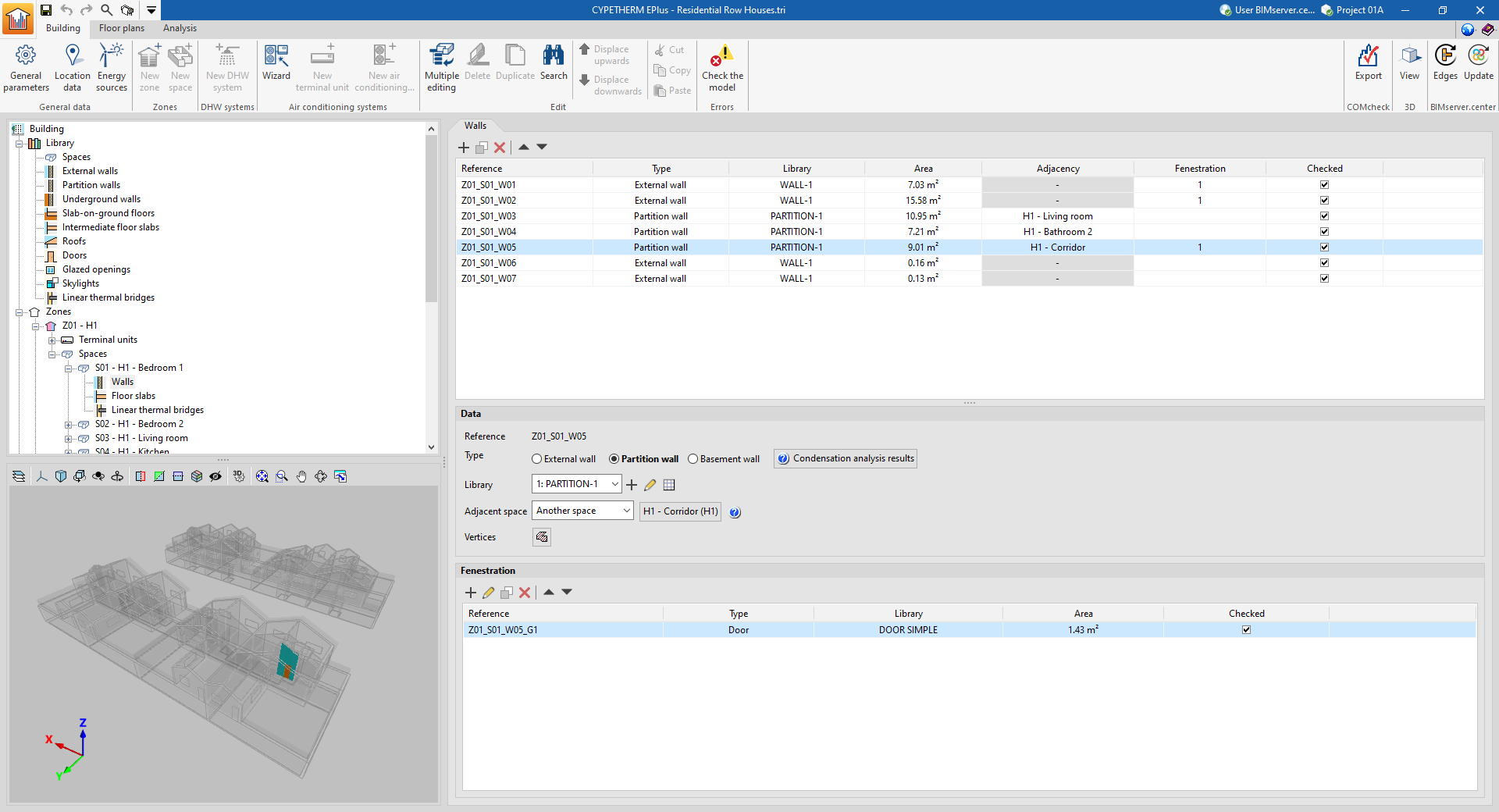
"Building" tab
The "Building" tab defines the general parameters, the site data and the building model.
The interface of this tab is structured in the following sections.
- Toolbar. Located at the top and contains the program's main features.
- Tree diagram of the building. Located at the top of the left-hand side and contains the elements that make up the design model.
- Main editing area. Located in the central area on the right and allows users to edit the properties of the selected element in the project tree.
- 3D model viewer. Located at the bottom of the left-hand side, it is used to visualise the position of the selected element in the tree or in the main area in the 3D model.
- Checks viewer. Appears at the bottom of the main editing area and informs of any warnings or errors found at the time the model is checked.
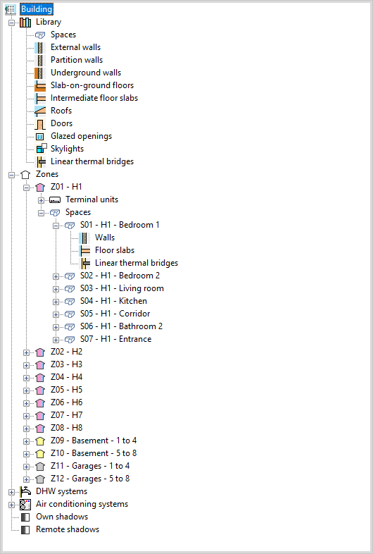
The above diagram contains the building model and consists of the following branches, which can be expanded and collapsed:
- Library. In the library, the types of space and building elements of the job are entered (spaces, partition walls, walls and floors in contact with the ground, slab-on-ground floors, roofs, doors, glazed openings, skylights and linear thermal bridges).
- Zones. In each zone, the spaces within it are entered by defining the walls (façades, party walls, partition walls and basement walls), floor slabs (floor slabs, floor slabs, overhangs and roofs) and linear thermal bridges. The terminal units of the HVAC system or systems covering the spaces in the area are also entered.
- DHW systems. The building systems for the production of domestic hot water (DHW) are defined.
- HVAC systems. The production and distribution subsystems of the heating and/or cooling system(s) of the job are defined.
- Own shadows. The surfaces of the building that do not belong to the spaces but that can cast shadows on façades and roofs, such as, for example, balcony slabs or defences, are defined.
- Remote shadows. The surfaces of remote obstacles that may cast shadows on the building are defined.
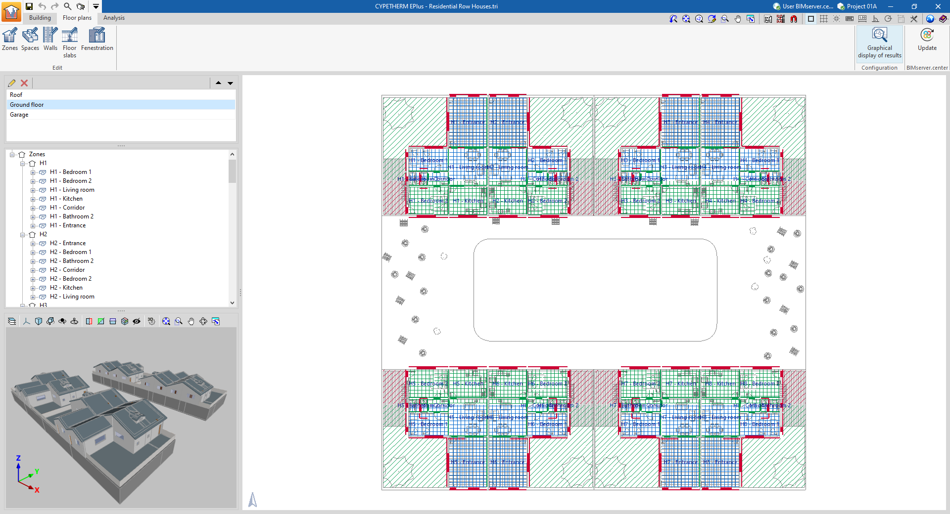
"Floor plans" tab
The "Floor plans" tab contains the drawings of each floor in the building, where the building elements are represented.
The interface of this tab is structured in the following sections.
- Toolbar. Located at the top and contains tools for editing the elements of the model and the configuration of the results query.
- Diagram of floor plans of the building. Located at the top of the left side and lists the floor plans available in the building.
- Tree diagram of the building. Located in the central part of the left side and contains a diagram of the elements in the model.
- Main display area. Located in the central area on the right and allows users to view and edit the properties of the elements of the model through a plan view.
- 3D model viewer. Located in the lower part of the left-hand side and allows the position of the selected element in the tree or in the main area to be viewed in the 3D model.
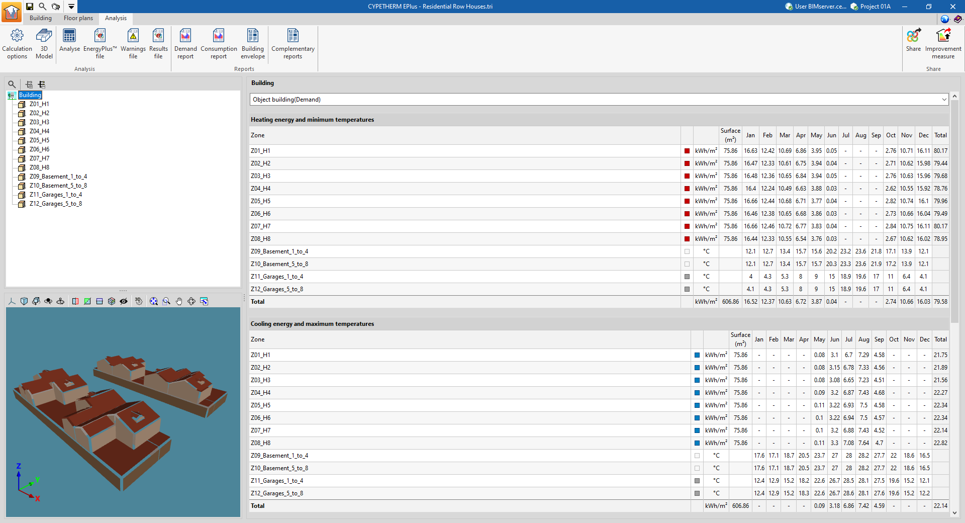
"Analysis" tab
In the "Analysis" tab, the simulation is launched and the analysis results are obtained and displayed.
If the job has not been analysed, a warning will appear on the screen indicating this. Once the job has been analysed, the results of the analysis will be displayed in the main window and the buttons for obtaining the reports will be illuminated.
The interface of this tab is structured in the following sections.
- Toolbar. Located at the top, it contains the utilities that allow users to configure and perform the calculation, as well as to obtain the files and the reports of the results.
- Diagram of the building's thermal zones. Located in the upper part of the left-hand side and shows the building's thermal zones.
- Main results display area. Located in the central area on the right and shows the results of the selected section in the diagram, either the whole building or a thermal zone. It shows the details of the simulation results month by month, according to the selection made in the diagram. The upper drop-down menu allows users to view the results of the different simulations carried out (demand or consumption).
- 3D model viewer. Located at the bottom of the left-hand side and shows the model of the building sent to the analysis engine, also available from the "3D model" option.
Sequence of input and output of data for the energy simulation of a building
The energy simulation of a building can be carried out in the program using the following input and output sequence:
- Create a new job (from "File", "New").
- Link to BIMserver.center. The building geometry, construction systems, shadows, lighting power of spaces and the definition of some air conditioning systems can be imported from the BIM model.
- In the "Building" tab, the definition of the building model is completed:
- Reviewing and defining the project’s general data (from the "General data" group), including general parameters and site data.
- Defining the characteristics of the spaces through the management of their libraries ("Building" side tree, "Library", "Spaces").
- (Optional) If the construction systems have not been imported, defining the characteristics of the building elements through the management of their libraries ("Building" side tree, "Library", "External walls/Partitions/Walls in contact with soil/Floors in contact with soil/Intermediate floor slabs/Roofs/Doors/Glazed openings/Skylights").
- Edge processing (via the "Edges" option in the top toolbar) for generating and processing linear thermal bridges.
- (Optional) Reviewing, adjusting and validating the data presented by the building model and its structure in zones, spaces and elements, own shadows and remote shadows (side tree "Building", "Zones/Own shadows/Remote shadows").
- Entering DHW systems and air-conditioning systems (via the tools in the side tree "Building", in "Zones", "Terminal units/ DHW systems/Air-conditioning systems", or via the blocks "DHW systems" and "Air-conditioning systems" in the top toolbar).
- Checking the building model (from "Errors", "Check the model") and correcting errors and warnings by editing the data in this tab.
- (Optional) Data consulting and editing elements in floor plans ("Floor plans" tab).
- In the "Analysis" tab, the design options are configured, the analysis is carried out and the results are viewed:
- Setting the design options ("Analysis" group, "Design options").
- Analysis and energy simulation of the building ("Analysis" group, "Analyse").
- (Optional) On-screen display of the analysis results in the main display area, at building or zone level (depending on the selection in the side tree "Building").
- Obtaining reports (using the options in the "Reports" group) and analysis files (using the options in the "Analysis" group).
- (Optional) Obtaining drawings (from the "Drawings" option in the "File" menu or at the top of the interface).
- Exporting to BIMserver.center ("BIMserver.center" group, "Share"). If an analysis of improvement measures is desired, the "Improvement measure" option is used for the export.
Examples of models for building energy simulation
Below is an example of a model of a building that can be developed in the program, showing the layout of the elements and the options that can be used to enter them into the model, and with which the energy simulation can be carried out:
Model of 8 single-family dwellings in a row
The architectural geometry is imported from a BIM model. The following elements must be reviewed and defined:
- Spaces
- Generated in the import of the BIM model. Defined from the "Building" tab, "Library" tree, "Envelopes".
- Partitions
- Generated when importing the BIM model. Defined from the "Building" tab, "Library" tree, "Walls in contact with soil".
- Walls in contact with soil
- Generated when importing the BIM model. Defined from the "Building" tab, "Library" tree, "Walls in contact with soil".
- Intermediate floor slabs
- Generated when importing the BIM model. Defined from the "Building" tab, "Library" tree, "Floor slabs".
- Roofs
- Generated in the import of the BIM model. Defined from the tab "Building", tree "Library", "Roofs".
- Floor slabs
- Generated when importing the BIM model. Defined from the "Building" tab, "Library" tree, "Floors in contact with the ground".
- Doors
- Generated when importing the BIM model. Defined from the "Building" tab, in the "Library" tree, under "Doors".
- Windows
- Generated when importing the BIM model. Defined from the "Building" tab, in the "Library" tree, under "Glazed openings".
- Linear edges and thermal bridges
- Edges generated in the import of the BIM model. Linear thermal bridges generated from the "Building" tab, in the "Edges" option.
- Shadows
- Generated when importing the BIM model.
- Spaces (not shown in the graphical representation)
- Generated when importing the BIM model. Defined from the "Building" tab, in the "Library" tree, under "Spaces".
- HVAC and DHW systems (not shown in the graphical representation)
- Generated from "HVAC systems", "Wizard".
Creating a new job, linking to a project and importing data
When launching the program and clicking on "New", a "New job" can be created. After entering the "File name" and "Description", the job can then be integrated into an existing project in BIMserver.center.
This is done in the "Project selection" window, which has the following options:
- On the left-hand side, users can log in with a BIMserver.center account.
- On the right-hand side is the "Select project" option to select an existing project. There is also the possibility to "Create a new project". In this case, the created project will be visible from BIMserver.center immediately.
Once the new job has been created, the program's general interface can be accessed. The project files can be shared or imported at any time during work via the "BIMserver.center" group, located at the top right of the general interface.
Importing BIM models
When creating a new job, after selecting or creating a project hosted on the BIMserver.center platform, the "Import of BIM models" window appears, which displays the files contained in the project in IFC format.
If there are several contributions in the project, the program can select the main or initiator file in the ‘Main (initiator)’ window. This file will provide the geometrical data for the generation of the building model in the program.
The program offers the possibility of including one or more of the existing models in the project. To do this, check the "Import" box and accept it.
In addition, this window offers the following options:
- Edges / DXF Templates
- Import edges (optional)
The building information model (BIM) includes the edges resulting from the intersection of the different building elements. The import of this geometric information, together with the zoning of the building introduced on the generated design model, makes it possible to obtain linear thermal bridges. - Update the DXF templates from the BIM model (optional)
- Import edges (optional)
- Assigning types
The building information model (BIM) includes the grouping of the different building elements into types. When this information is available, and during the import process, the corresponding libraries of types can be generated on the design model, maintaining the grouping of elements. The description of the types created is searched for, by reference, in the indicated directory, and those that are not found are left to be described.- Create types for the elements (optional)
- Flag as checked the elements with a typology attached (optional)
- Directory for searching typologies (optional)
By activating this option, a directory can be selected on the disk where the type library files are stored. This is used to import the type libraries previously created in other jobs and exported to that directory and to automatically assign them to the spaces, elements and openings of the imported model. To do this, the references of the types in the selected directory must coincide with the references of the types of elements in the imported model.
Final import configuration
The program will then open the "General parameters" and "Site data" windows to configure the corresponding parameters. After this, an "Information" message will be displayed indicating that the import is complete.
The program opens in the "Building" tab and will have generated the model geometry and element libraries from the existing data in the project or in the selected directory. At this point, the data required to continue working on the model can be completed.
Setting the general project parameters
Within the "Building" tab, in the "General data" group of the main toolbar, the following option can be found, which is used to set the general parameters of the project:

General parameters
In the "General parameters" window, which opens when clicking on this option, the following general data of the building are defined:
- Condensation
Optionally, the program includes a check for the existence of surface and interstitial condensation according to EN ISO 13788, providing results for each construction system. If this option is activated, the energy simulation will not be allowed to be carried out if the condensation checks are not fulfilled.- Check for the existence of surface and interstitial condensation in accordance with ISO 13788 (optional)
- Air permeability of the building envelope
Air permeability values are defined for the different types of opaque elements and openings forming the building envelope. A limit value of the air change ratio at a differential pressure of 50 Pa (n50) can be defined, which shall be compared with the value calculated for the building in the "Thermal envelope" report.- Limit value of the air change rate with a differential pressure of 50 Pa (optional)
- Air permeability of the building envelope (External walls, Roofs, Doors, Openings)
This section is used to enter the air permeability for a reference pressure of 100 Pa for the selected elements.
- Thermal envelope
Optionally, the program includes the verification of limit values of thermal transmittance (U) for the different types of building elements. These values can be defined in this section. If any of the components of the thermal envelope of the building exceeds the established limit value, a warning will appear when clicking on the "Check model" option.- Boundary conditions of the thermal envelope (optional) (External walls, Party walls, Basement walls, Vertical internal partition; Floors with their lower surface exposed to the environment, Slab-on-ground floors, Roofs, Horizontal internal partition; Doors, Windows, Skylights)
- Daily DHW demand
The program allows users to define the domestic hot water (DHW) demand with a single value for the whole building, or to define a value for each thermal zone.- Total demand of the building
Enters a single demand value for the whole building.- Daily DHW demand
- Reference temperature
- Solar contribution distribution (Constant / By month)
- Percentage of DHW demand satisfied using solar energy
- Demand by thermal zone
If this option is chosen, the parameters related to DHW are described in each of the building's thermal zones, which can be selected and edited in the building element tree.
- Total demand of the building
Setting the location data
Within the "Building" tab, in the "General data" group of the main toolbar, there is the following option, which is used to set up the location data:

Location data
The "Location data" window, which opens when clicking on this option, describes the climatic data of the location where the building is located.

The energy simulation shall be carried out with the climate data file indicated in the "Climate data file" section, located in the upper left corner of this panel:
- Climate data file
Specifies the location of the EPW (EnergyPlus Weather Format) weather data file for the location of the building. On the official EnergyPlus™ website (energyplus.net/weather) the .epw weather data files for more than 2100 locations worldwide are available free of charge.
The "Import the values from the selected climate data file" wizard is used to fill in the panel data with the information contained in the selected climate data file.
The following data can be filled in from the import of climate files or adjusted later on: The following data can be filled in from the import of climate files or adjusted later on:
- Location data
- City, Altitude, Altitude, Latitude, Longitude, Time zone
This data is informative and is involved in the drafting of the results reports. In the energy simulation, these parameters are automatically read from the climate data file with extension .epw. - SCOP climatic conditions (Warm climate / Average climate / Cold climate)
Selects the climatic conditions according to the building's location. On the right, the program offers an aid to select the climate corresponding to the region where the project is located. This selection is used to determine the average seasonal performance of DHW production (SCOPACS) of the heat pump units.
- City, Altitude, Altitude, Latitude, Longitude, Time zone
- Orientation
Rotates the building. The orientation of the building is displayed in the "Floor plans" tab by means of the arrow in the lower left corner of the plan view. - Undisturbed ground temperature
The ground temperature (without influence of ambient conditions) is defined as a constant value for the whole year or by month. These values are used in the calculation of heat losses to the ground.- Constant (Average annual temperature) / Monthly (Temperature by month)
- Domestic hot water
The temperature of the mains water is defined, with a constant value for the whole year or by month. These values are used in the calculation of the energy demanded for the production of domestic hot water (DHW).- Constant (Average annual temperature) / Monthly (Temperature by month)
- Condensation
The outdoor ambient temperature and humidity values to be used for the condensation check are defined. Constant values can be defined for the whole year or by month.- Outdoor temperature
- Constant (Average annual temperature) / Monthly (Temperature by month)
- Outdoor relative humidity
- Constant (Average annual humidity) / Monthly (Monthly humidity)
- Outdoor temperature
The outdoor temperature, wind distribution and solar irradiance graphs shown in this panel reflect the data in the selected climate data file:
- External temperature
Daily maximum, daily minimum and daily average temperatures in a given year of the selected climate data file. - Wind distribution
Wind speed in the cardinal and intercardinal directions according to the selected climate data file. - Global irradiance on a horizontal surface
Global irradiance on a horizontal plane for different times of day and different days in a given year of the selected climate data file.

Defining energy sources
Within the "Building" tab, in the "General data" group of the main toolbar, the following option can be found, which allows the configuration of the project's energy sources:

Energy sources
- Energy conversion factors (Primary energy / Final energy; % Non-renewable; kg-CO2 / kWh Final energy)
By editing this section, users can define the conversion factors from final energy to primary energy, non-renewable primary energy and CO₂ emissions, for the different types of energy carriers available in the programme. The settings for different countries can be imported using the options on the right. The available energy vectors are as follows:- Electricity
- Natural gas
- Diesel
- LPG
- Coal
- Densified biomass (pellets)
- Biomass
- Environment
- Final generated and self-consumed electricity
This is defined as the annual amount of electrical energy generated and consumed by the building itself, usually due to the use of on-site renewable sources (solar photovoltaic, mini-wind, mini-hydro, etc.).- Defined
Enters the value of final generated and self-consumed electrical energy, which may be different from the value of final electrical energy consumed. The indicated value will be subtracted from the annual final electrical energy consumption, to determine the part of the electrical energy consumption coming from the grid. - All the electricity consumed is generated
The program will consider that all electrical energy consumed in the project is generated in the building itself.
- Defined
Library management tools
The "Library", accessible in the side diagram of the "Building" tab, contains the description of the types of elements that can be used in the building model.
The following libraries of elements are available:
- Spaces
- External walls
- Partition walls
- Underground walls
- Slab-on-ground floors
- Intermediate floor slabs
- Roofs
- Doors
- Glazed openings
- Skylights
- Linear thermal bridges
Each library type can be "In use" or not, whether or not it is associated with any of the elements of the "Zones" tree, which organises the components of the building model.
The elements of each of the libraries are created and managed using the tools at the top of the list, described below..
Managing elements in library lists
The elements are organised in lists in multiple windows of the program. The following options for managing and editing items are provided in the library lists:
![]() | Add | Adds a new element to the list. |
![]() | Edit | Accesses the editing panel of the selected element. |
![]() | Copy | Duplicates the selected element, adding a copy to the list. |
![]() | Delete | Removes the selected element from the list. |
![]() | Assign | Assigns the characteristics of the selected element to other elements in the list. |
In the process of importing or updating the BIM model, a directory can be defined to search for types. If this directory contains CYPETHERM EPlus elements whose references coincide with those of the elements of the current work, the program will automatically import their properties.
Importing and exporting library elements to files on disk
The use of libraries can be used to define elements in the current job and save them on disk for use in other projects. The options related to this use are as follows:
![]() | Import the elements saved in the drive to the project | Imports the elements stored on disk into the job, adding them to the list. If the element (with the same reference) already exists in the job, its data will be replaced. |
![]() | Update the elements used in the project | Updates the elements defined in the job, with the properties of the elements saved on disk with the same reference. |
![]() | Export the element to a file | Exports the selected element to a file, so that it can be imported later. |
![]() | File selection with initial values for the creation of a new job | Selects a list of elements saved on disk to be loaded into the library when creating a new file. |
Managing the space library
Determining the characteristics of the spaces in the project library is necessary in order to classify them as occupied or unoccupied, as well as to detail the parameters relating to ventilation, lighting, occupancy and internal equipment, which affect the energy simulation carried out by the program.
The tools for managing the space libraries of the model can be found in the "Building" tab and, within the outline of the left-hand side area of the "Project" definition, in the "Library" tree, then selecting the "Spaces" level.
The concepts defined for each type of space are those related to internal heat gains. Depending on the type of internal gains present, two types of space are identified:
Occupied spaces
Occupied spaces are indoor spaces intended for people to use. In these spaces, the ventilation flow rate, the installed power of lighting, the occupancy and activity level and the installed power of the internal equipment can be defined.
Each of these concepts can be defined by a nominal value and a schedule, which changes this nominal value over the year by applying a percentage. If no schedule is defined, the nominal value is considered constant throughout the year.
The definition of occupied spaces is based on the configuration of the following parameters:
- Space classification: Occupied
- Ventilation (optional)
- Schedule (optional)
- Lighting (optional)
- Installed light power
- Radiant fraction
- Space fraction
- Schedule (optional)
- Occupancy (optional)
- Activity level
- Sensible fraction (optional)
- Radiant fraction
- Schedule (optional)
- Equipamiento interno
Internal equipment entries with the following characteristics can be added to this table:- Design power
- Radiant fraction
- Latent fraction
- Type of energy vector
- Schedule (optional)
To the right of each of these concepts, a wizard button is provided which gives nominal values according to the use of the space and other parameters, based on the indicated bibliography.
In addition, to the right of the panel there is another wizard that covers all four concepts and offers values for the entire space. The "Space types" offered by this wizard are as follows:
- Residential
- Offices
- Retail
- Hotel
- Public attendance
- Educational
- Hospital
- Industrial
- Restaurant
- Assisted living facility
Unoccupied spaces
Unoccupied spaces are indoor spaces that are not intended for people to use on a permanent basis. They are therefore spaces that do not require air-conditioning (e.g. a garage, a storage room or a technical room). In these rooms, the ventilation flow rate, the installed lighting power and the installed power of the internal equipment can be defined.
Just like for occupied spaces, each of these concepts can be defined by a nominal value and a schedule, which modifies this nominal value over the year by applying a percentage. If no schedule is defined, the nominal value is considered constant throughout the year.
The definition of unoccupied spaces is based on the configuration of the following parameters:
- Space classification: Unoccupied
- Ventilation (optional)
- Schedule (optional)
- Lighting (optional)
- Installed light power
- Radiant fraction
- Space fraction
- Schedule (optional)
- Internal equipment
Internal equipment entries with the following characteristics can be added to this table:- Design power
- Radiant fraction
- Latent fraction
- Type of energy vector
- Schedule (optional)
Defining schedules
Schedules are used to define the pattern of variation, use, or activation of different resources or aspects of the project over the hours of the day, days of the week, and months of the year.
These aspects include the variation of ventilation, lighting, occupancy or internal equipment of the spaces, the profile of the setpoint temperatures for heating and/or cooling in each thermal zone, the activation profile of the solar protection fittings, the operational conditions of the air infiltrations in the zones or the time profile that defines the value of some parameters of the systems.
The schedules are detailed by activating or selecting the "Schedule" option found in the definition panels of the different aspects mentioned above, and then clicking on the edit option that will appear next to it.
If no schedule is defined for a certain aspect, the program will assume 100 % usage at all times of the day, every day of the year.
In the window for editing a schedule, the program can modify the following data:
- Reference
Schedule reference.
- Type of schedule
- Annual
Selects a single schedule for the whole year. - Weekly
Selects a schedule for the whole week. If the "Distinguish programming by month" checkbox is activated, a schedule can be selected for the whole week of each month of the year. - Working days / Weekend
Selects a schedule for weekdays and another schedule for weekends. Users can "Consider Saturday as being a working day" by activating the corresponding checkbox. If the "Distinguish programming by month" checkbox is activated, users can select a schedule for weekdays and a schedule for weekends for each month of the year. - All week
Selects a different schedule for each day of the week. If the "Distinguish programming by month" checkbox is activated, a schedule can be selected for each day of the week of each month of the year.
- Annual
In order to be selected, the available schedules must first be defined using the "Profiles" option on the right.
Available schedules
When creating or editing each available schedule, the following data must be entered:
- Reference
Schedule reference - Profile definition
- Off
The resource will be deactivated. - On
The resource will be activated. In some cases the "Value" of the activation percentage can be defined.
- Off
- By hour
This section is used to define an hourly profile, indicating a value for each of the 24 hours of the day, either a schedule between 0 and 100 %, the activation status (On / Off) or a certain temperature value. To do this, simply click on the corresponding height on the graph to define the value, the activation status or the desired schedule for each hour.
The schedule created can be imported and exported to files on disk using the corresponding options on the right-hand side of the panel.
Managing libraries of opaque building elements
Defining the characteristics of the building elements in the project libraries is necessary to detail the data related to their thermal behaviour, including the possibility of specifying the composition of layers of materials and the technical characteristics of each of them, such as thermal conductivity or thermal resistance. This data can be entered manually or based on different catalogues and reference standards with predefined materials and will affect the energy simulation performed by the program.
The tools for managing the libraries of opaque building elements of the model are found in the "Building" tab and, within the outline of the left-hand side area of the "Project" definition, in the "Library" tree, then selecting the corresponding level.
Categories of opaque building elements
The opaque building elements are classified into the following categories within the library:
- External walls ("Opaque" option). Vertical external walls in contact with the external environment (façades) or in contact with the spaces of another building (party walls). In the definition of an external wall, users must specify whether it is a "Party wall" and whether it is "Adiabatic".
- Partition walls. Interior partitions. They are arranged to separate the interior of the building into different rooms.
- Underground walls. These vertical external walls in contact with the ground are used to build floors below ground level (basements).
- Slab-on-ground floors. Horizontal envelopes (floor slabs, raised floor slabs) in contact with the ground.
- Intermediate floor slabs. Intermediate floor slabs are the horizontal or slightly inclined lower envelopes between one storey and another, i.e. the floors of each intermediate storey of the building. This category also includes overhangs, i.e. external walls in contact with the exterior at the bottom.
- Roofs. Upper envelopes in contact with the outside environment.
General definition of building elements
When adding or editing an opaque building element type in the library, a window opens where the following aspects can be managed:
- Reference
Reference of the type of building element. - Define by layers / Simplified input
Indicates whether the thermal characteristics of the element are defined by entering the data for each of the component material layers or through a simplified input.
In some cases, it is also possible to import complete building systems from Open BIM Database:
- Connection to Open BIM Database
Login to the Open BIM Database. - Importing manufacturer data
Imports the data of complete building systems from one of the available manufacturers by selecting the catalogue and the desired product.
Additionally, the options in the right-hand column of the window can be used to import and export the data of the defined element type to files on disk.
Specific options when defining opaque building elements
In addition, the following specific options may appear, depending on the type of element selected:
- Opaque / Glazed (in "External walls")
Indicates whether the envelope is opaque, defined in the same way as the rest of the opaque building elements, or glazed, in which case it is defined by entering the data of the "Opaque fraction" (such as solar transmittance and solar factor) and the "Glazed fraction" (such as thermal transmittance, opaque fraction of the opening and absorptivity), in addition to the "Air permeability for a reference pressure at 100 Pa", as is done in glazed openings. The latter option allows curtain walls to be simulated. - Absorption coefficient (in "External walls", "Partition walls", "Intermediate floor slabs" and "Roofs")
The absorption coefficient fluctuates between 0 and 1. Only one value of the absorption coefficient of the building element is indicated, which must correspond to the external layer (on which the solar radiation strikes). The value can be imported with the wizard available on the right:- Import absorptance
The value of this coefficient is lower on light surfaces, and higher on dark surfaces.
- Import absorptance
- Party wall (optional) (in "External walls")
Indicates that the envelope is a party wall, rather than a façade. In this way, the temperature conditions of the external environment are considered, with no exposure to the sun or wind (zone boundary envelope). The following option is checked if it is to be considered completely adiabatic, i.e. there is no heat transmission through this element:- Adiabatic (optional)
- Soil thermal conductivity (in "Slab-on-ground floors" and "Intermediate floor slabs")
The soil conductivity varies according to its type. The value can be imported with the wizard available on the right:
Import typical values
The lowest values correspond to gravels and silts; sands provide intermediate values, while rock provides higher values.
- Specific options in the definition of "Slab-on-ground floors"
Slab-on-ground floors can be used to define raised floor slabs or screeds:- Raised floor slabs
By selecting "Raised floor slabs", the program allows users to enter the information about the cavity under the slab and other data such as the following:- Wind protection (Sheltered / Average / Exposed)
- Area of ventilation openings per perimeter length of underfloor space
- Thermal transmittance of walls of underfloor space above ground level
- Soil thermal conductivity
- Average depth of the cavity floor below ground level
- Thermal resistance of the basement walls
- Screed
For screeds, peripheral insulation can be added and its characteristics can be defined:- With edge insulation (optional)
- Type of insulation (Vertical / Horizontal)
- Thermal resistance
- Thickness
- Thickness of depth
- Soil thermal conductivity
- Import typical values
- With edge insulation (optional)
- Raised floor slabs
Define by layers
If the building element is defined by layers, the program offers a table where you can add, edit, copy, delete or reorder the material layers included in the building element.
The layers of materials that make up the space are defined in order, from the outside to the inside in the case of vertical spaces (walls), and from the top to the bottom in the case of horizontal spaces (floor slabs).
The materials that make up the opaque external walls are classified into solid materials, air cavities (including ventilated ones) and vapour barriers. The thermal properties of each material must be defined, according to their "Type of layer".
When entering a material layer, the following parameters need to be specified in its definition window:
- Connection to Open BIM Database
Login to the Open BIM Database. - Importing manufacturer data
Imports the data of complete building systems from one of the available manufacturers by selecting the catalogue and the desired product. - Reference
Reference of the layer of material. - Type of layer
There is a choice between a solid layer, an air cavity or a vapour barrier.- Solid layer
- Thickness
- Density
- Conductivity / Thermal resistance
- Specific heat
- Water vapour diffusion resistance factor
- Air cavity
- Thickness
- Thermal resistance
- Vapour barrier
- Equivalent air thickness
- Solid layer
- Colour / Weave / Aspect of the material
- Adjusts the graphical representation of the layer material.
The options in the right column of the definition window of each material layer can be used to automatically import the material data from the information provided by different catalogues and codes, such as the following:
- HULC library materials
- Air cavities described in UNE-EN ISO 6946
- Materials described in EN ISO 10456
Additionally, there are options in the right-hand column of the window to import and export the defined material data to files on disk.
Simplified input
The simplified input of the element type involves entering its global thermal properties. This is useful if the layer-by-layer data is unknown, if these properties are available or if they have been calculated outside the program.
- Simplified input
- Thickness
- Density
- Specific heat
- Thermal description
- Heat transfer coefficient
- Heat capacity per surface unit
The "Heat capacity per surface unit" property does not play a role in the simulation, it is only used in the wording of the result lists.
Managing the libraries of openings
The characteristics of the openings must be defined in the project libraries to detail the data related to their thermal behaviour. This data can be entered manually or based on different catalogues and reference standards with predefined materials and will affect the energy simulation carried out by the program.
The tools for managing the libraries of openings in the model can be found in the "Building" tab and, within the outline of the left-hand side area of the "Project" definition, in the "Library" tree, then selecting the corresponding level.
Categories of openings
The openings in the building are classified into the following categories within the library:
- Doors. These are entirely opaque openings.
- Glazed openings. These are translucent openings in vertical enclosures, such as glazed windows and doors.
- Skylights. These are translucent openings in horizontal envelopes.
It is also possible to define glazed envelopes with the following option, which behave similarly to glazed openings:
- Envelopes ("Glazing" option). These are vertical translucent envelopes in contact with the external environment, such as curtain wall façades.
Defining doors
The following parameters must be defined for the types of doors:
- Reference
- Description
- Heat transfer coefficient (U)
Heat transfer coefficient of the door. - Absorptance
The absorbance coefficient fluctuates between 0 and 1. The value can be imported with the wizard available on the right:
Import absorptance
The value of this coefficient is lower on light surfaces, and higher on dark surfaces.
Defining glazed openings and skylights
The following parameters must be defined for glazed openings and skylights:
- Air leakage rate for a reference pressure of 100 Pa. This value is used for calculating infiltration and is given by the class of the window. Usual values can be imported using the wizard on the right.
The rest of the opening parameters are defined in the following tabs:
"Glazed fraction" tab
Specifies the heat transmission coefficient (U-value) and the solar factor of the opening. If the "Opaque fraction" tab is activated, the values indicated in this panel apply only to the glazed fraction of the opening. Otherwise, they will affect the complete geometry of the opening.
- Connection with Open BIM Database
Logs into the Open BIM Database. - Importing manufacturer data
Imports glazing data from one of the available manufacturers by selecting the catalogue and the desired product. - Heat transfer coefficient (U)
Heat transfer of the glazing fraction. - Solar factor
- Solar factor of the glazing or the proportion of solar radiation that the glazing allows to pass through, in percent. The lower the solar factor, the less solar radiation enters the interior.
"Opaque fraction" tab (optional)
Specifies the opaque fraction or frame fraction of the opening and its thermal properties, as well as the existence of thermal bridges due to the coupling between the different parts forming the opening, which are defined by their length and their linear thermal transmittance.
- Heat transfer coefficient (U)
Heat transfer coefficient of the opaque fraction. - Opening opaque fraction
Proportion of the opening in percent occupied by the opaque part (frame or joinery). - Absorptance
Absorption coefficient of the radiation incident on the frame. - Junction between frame and glazing (optional)
Activating this box declares the existence of thermal bridges due to the coupling between the frame and the glazing.- Length
Length of thermal bridges between the glazing and the frame. - Linear thermal transmitance
Linear thermal transmittance of thermal bridges between frame and glazing. A wizard for determining this parameter with values from EN ISO 10077-1 is provided on the right-hand side.
- Length
- Junction between frame and opaque panels or blind box (opcional)
Activating this box declares the existence of thermal bridges due to the junction between the frame and the opaque panels or the blind box.- Length
Length of thermal bridges between the frame and the opaque panels or the blind box. - Linear thermal transmittance
Linear thermal transmittance of thermal bridges between the frame and the opaque panels or the blind box.
- Length
"Accessories" tab
Adds solar shading accessories, either external (blinds) or internal (curtains), and defines their activation.
- With solar protection accessories (optional)
- Name
- Type (Interior shade / External shade)
- Solar transmission coefficient
Proportion of solar radiation that the accessory allows to pass through, in per cent. - Thickness
- Conductivity
- Shading control type
- Always on
Considers that the defined shading is always on at all times of the year. - Always off
Considers that the defined shading is always off. - On if schedule allows
Creates and edits an hourly, daily, weekly or monthly schedule that details the times when shading is active or inactive.- Schedule
- On if high solar radiation incident on window
Defines a maximum solar radiation value, above which the shading is considered to be active.- Solar radiation
- Always on
"Shading elements" tab
Shading elements are used to simulate the effect of façade projections such as outside reveal depth, overhangs over the window or lateral projections that produce shading on the opening, if they have not been defined in the geometric model and included or inserted in the tree of building elements.
- Overhang (Horizontal projection) (optional)
- Overhang projection depth (PH)
- Vertical offset from fenestration top (RH)
- Angle
- Left fin (Left vertical projection) (optional)
- Fin projection depth (PV)
- Horizontal offset from fenestration edge (RW)
- Lateral derecho (proyección vertical) (opcional)
- Fin projection depth (PV)
- Horizontal offset from fenestration edge (RW)
The program displays a generic diagram at the bottom of the screen with the layout of the opening and possible shading elements to help in defining its parameters.
The options for defining shading elements in glazed openings and skylights allow users to enter this data specifically if it cannot be obtained from these other sources of information.
"Plane thermal bridges" tab
Plane thermal bridges are used to define the building elements that make up the flat surfaces surrounding the opening if their characterisation differs from the building element where the opening is located and in order to take into account the heat transmission through them.
The plane thermal bridges available are as follows:
- Lintel (optional)
- Blind box (optional)
- Jambs (optional)
- Windowsill (optional)
- Niche (optional)
The program shows a generic diagram on the right-hand side with the representation of the opening and the possible plane thermal bridges, which helps to understand their layout.
In each of them, the value of the width must be defined. This width, together with other data such as the width or height of the opening, will provide the area of the plane thermal bridge. In the case of niches, the plane thermal bridge extends from the floor to the opening.
Managing the linear thermal bridge library
Defining the characteristics of the linear thermal bridges in the project libraries can be used to detail their data, such as the linear thermal transmittance. This data can be entered manually, imported from reference standard catalogues, or calculated using a linear finite element design model, and will affect the energy simulation performed by the program.
The tools for managing the linear thermal bridge libraries of the model can be found in the "Building" tab and, within the outline of the left-hand side area of the "Project" definition, in the "Library" tree, then selecting the "Linear thermal bridges" level.
Linear thermal bridges can occur at the edges or intersections of the different building elements between the building and the ground.
The "Aristas" option in the top toolbar is then used to edit and adjust the linear thermal bridges of the building as a whole. This way, the program automatically modifies the data of the linear thermal bridge types according to the configuration parameters of the edge processing.
However, a particular type of bridge can be edited or modified specifically using the options discussed in this section.
Editing linear thermal bridge types
When creating or editing a thermal bridge type in the library, the program offers the possibility to configure the following parameters:
- Reference
- Description
- Psi (W/(m·K))
Linear thermal transmittance. - Value (Undefined / Entered / ISO 14683 / ISO 10211)
Origen of the value. Thermal bridges marked with the "Not defined" option will not intervene in the energy simulation. - Type of intersection
The available types include the following:- Intersection of façade with floor slab
- Meeting between façade and roof
- Intersection of façade with overhang
- Intersection of façade with screed
- Incoming corner of the façades
- Projecting corner of the façades
- Window opening
- Column
- Other (not considered in the reference building)
Automatic data import
Users can automatically import linear thermal bridging data using the following standards and methods:
- ISO 10211
Determines the thermal transmittance of linear thermal bridges by means of a finite element analysis based on EN ISO 10211. This method is the same as the one used by independent programs such as CYPETHERM BRIDGES. The program displays a wizard with the following tabs:- About…
Information text on the design method used and its implementation in the program. - Types
Selects the type of thermal bridge. - Model
Description of the thermal bridge model by defining the layers of material located in each of the positions indicated in the graph. - Report
Report on the analysis of the linear thermal transmittance of the thermal bridge by means of the finite element analysis proposed in the indicated standard.
- About…
Tree of zones, terminal units, spaces and building elements
On the "Zones" level of the left side panel of the "Building" tab is the tree diagram of the building elements (describing the structure, organisation and geometrical data of all elements that make up the building model) that will be used in the energy simulation.
In this diagram, the building is divided into one or more thermal zones, which contain the building spaces. A thermal zone consists of a group of spaces that share operational temperature conditions.
Within each thermal zone, the diagram of the building defines the spaces it contains and the terminal units of the air-conditioning system that serve these spaces. In turn, within each space, the walls, floor slabs and associated linear thermal bridges are shown.
The structure is as follows:
- Zone
- Terminal units
- Spaces
- Space
- Walls
- Floor slabs
- Linear thermal bridges
- Space
Creating and editing the building tree
The geometry, structure and distribution of elements in this tree are imported from the geometric model in the process of creating a new building or updating the project information in BIMserver.center.
In any case, adjustments can be made freely on this tree within the program, by entering, deleting or editing the elements it contains. To do this, the different options available in the context menu that appears when right-clicking on each level, in the upper toolbar of the interface or on the tables of available elements can be used.
The elements in this tree, which include spaces, opaque building elements, openings and linear thermal bridges, are characterised based on the selection of the different types of elements previously created in the libraries.
New zone
To add a new thermal zone, select an existing zone in the building diagram and click on the "New zone" toolbar button. A pop-up window with the zone editing panel appears. By clicking on "Accept" the new empty zone will be displayed in the building diagram.
New space
Since the building spaces and their building elements are imported from the BIM model, it is usually not necessary to create new spaces, although the program has a function for this purpose. To add a new space to the zone, select the "Spaces" section within the zone in the building diagram and click on the "New space" toolbar button. This opens a pop-up window with the enclosure editing panel. Clicking "Accept" will display the new empty space in the building diagram.
Sorting zones and spaces
To sort the existing building spaces into the different zones, the following "Edit" tools are provided in the upper toolbar:
- The "Displace upwards" and "Displace downwards" buttons can be used to rearrange the elements of the diagram, including zones and spaces. These tools can also be used to move a space from one thermal zone to another.
- The "Multiple editing" option includes a wizard to edit the properties of different types of building elements at once. Among its features is the possibility to assign the "Spaces" to the different zones and to modify their library type. To do this, select the elements to be assigned the properties indicated in the "Selection" column, click on the "Zone" or "Type" assignment options, and accept the window.
Editing thermal zones in the building tree diagram
When a thermal zone is selected in the tree diagram in the left-hand side panel of the "Building" tab, the 3D model viewer lights up and the "Zone" panel is displayed in the main area, where the following properties of the zone are defined:
- Reference
The numbered reference of the zone is automatic and depends on its position in the diagram.
- Name
Name of the zone. This parameter can be edited directly.
- Classification of the zone ( Habitable / Non-habitable / Not defined)
All spaces included in the zone must be the same type (habitable or non-habitable) as the one chosen in this drop-down list. In the tree diagram, a zone classified as non-habitable or not defined will be shown with a grey symbol. A zone classified as habitable will have a coloured symbol depending on its operational conditions: yellow if no setpoint temperature has been defined (unconditioned habitable zone), red if a heating setpoint temperature is defined and blue if a cooling setpoint temperature is defined.
"Operational conditions and indoor comfort" section
Defines the operational conditions and comfort temperatures of the thermal zone. All spaces included in the zone share these conditions.
- Heating (optional)
Defines the heating setpoint temperature of the zone by means of an hourly profile. - Cooling (optional)
Defines the cooling setpoint temperature of the zone by means of an hourly profile.
- Editing advanced properties
Using the edit option on the right-hand side of the section, a maximum and minimum indoor comfort temperature can be defined. These temperature values are used in the "Indoor comfort" report to make comparisons with the indoor temperature of the zone. These comfort temperatures are not used in the EnergyPlus™ simulation.- Minimum comfort temperature (optional)
- Maximum comfort temperature (optional)
"Ventilation and infiltration" section
This section defines the ventilation and air infiltration of the zone.
- Editing advanced properties
The following parameters can be defined using the edit button on the right-hand side of the section:- Ventilation
The type of ventilation must be defined for all spaces in the zone, between:- Natural
The ventilation flow defined in the zone spaces enters directly. - Mechanical
The characteristics of the fan(s) (dual flow option) driving the defined ventilation flow in the spaces of the zone are defined:- Type of flow (Mechanical intake / Mechanical extraction / Double flow)
- Electric power of the fan
- Via the air conditioning system
The defined ventilation flow in the spaces of the zone shall be provided by the defined air-conditioning system associated with the zone, which shall be compatible with this function.
- Natural
- Infiltrations (optional)
The existence of infiltrations in each zone can be defined, i.e. a flow of air from the outside that enters the group of rooms in an undesired way. Different possibilities of defining this flow rate are offered, through two design methods and different schedules.- Analysis method: Enhanced Model (ASHRAE)
This calculates the infiltrations using the indicated design model. The following parameters must be defined:- Flow coefficient
This can be defined directly or calculated from the data entered.- Defined
- Calculated
- Intake openings (optional)
- Surface
- Intake openings (optional)
- Analysis data
The program offers tools for defining this data by clicking on the buttons on the right-hand side of the screen.- Stack coefficient
- Pressure exponent
- Wind coefficient
- Shelter factor
- Flow coefficient
- Analysis method: Design flow
Used to directly enter the flow rate due to infiltration. - Operating conditions (Only with nil ventilation / Schedule / Always)
Establishes the conditions under which infiltration occurs in the zone.
- Analysis method: Enhanced Model (ASHRAE)
- Ventilation
"DHW" section
This section will appear in each heating zone if in "General parameters" the "Demand per heating zone" option has been selected under "Daily DHW demand".
Thus, the following parameters are defined in relation to the domestic hot water demand in each zone of the building. If the "Total building demand" option has been chosen, these definitions have to be made for the total building in the "General parameters".
- Daily DHW demand
Volume of domestic hot water (DHW) consumed in a day in the zone. - Editing advanced properties
The following parameters can be defined using the edit button on the right hand side of the section:- Reference temperature
Production temperature of the DHW volume defined in "Daily DHW demand". - Solar contribution distribution
The percentage of the energy demand for DHW production covered by the solar thermal system of the building is defined. A constant or monthly value can be defined.- Constant / Monthly
- Percentage of DHW demand met by solar energy
- Reference temperature
"Condensation" section
This section defines the indoor environment parameters for calculating the check for surface and interstitial condensation if this option has been activated under "General parameters".
- Editing advanced properties
The following parameters can be defined using the edit button on the right hand side of the section:- Relative internal humidity
- Critical surface humidity
- Internal air temperature during the winter months
- Internal air temperature during summer months
- Heating period (number of days per month)
- Cooling period (number of days per month)
- Psychrometric diagram
Displays the indoor air temperature and humidity points (red colour) defined in this section, and the outdoor air defined in the "Location data" panel.
Editing spaces in the building tree diagram
Within each zone, the spaces that make up the zone are defined. The building spaces and their building elements are imported from the BIM model, so the parameters that appear in this section will be obtained automatically.
When any space is selected in the tree diagram in the left-hand side panel of the "Building" tab, it is highlighted in the 3D model viewer and the "Space" panel, where the properties of the space are defined, is displayed in the main area.
"Space" panel
A space is defined by its associated type, among those available within the library, and its general geometrical characteristics, such as area and volume:
- Reference
The numbered reference of the space is automatic and depends on its position in the diagram.
- Name
Name of the space. This parameter can be edited directly.
- Library
Selection of the space type from the drop-down menu from those available in the "Library". The program can create, edit or directly manage the libraries of space types with the options to the right of the drop-down menu.
- Area
Area of the space. This value is used to compute the simulation results per unit area. Spaces without a floor slab area ("Area" equal to 0) can be defined, provided that at least one space in the same thermal zone has an "Area" value greater than 0.
- Volume between the floor and suspended ceiling
Volume of the space. The space between the floor and the suspended ceiling.
- "Illumination" section
An individualised value of installed lighting power can be defined for each space. If this option is checked, the defined value will replace the value of the corresponding library type. This option will only be available if the space type chosen in "Library" has a lighting load defined ("Lighting" checkbox activated). This data can be imported from the BIM model information.- Installed light power (optional)
In the diagram of the building, within each space, the building elements that compose it and the thermal bridges associated with the space are visualised and defined.
Building components in the space: walls and floor slabs
The building elements of the space are divided into two groups: "Walls" (vertical elements) and "Floor slabs" (horizontal elements). By selecting each of these groups, the main area on the right side of the interface is displayed:
- in the first tab (with the "Wall" or "Floor slabs" name), a table with the report with the list of concrete elements that make up the space;
- and in the second tab ("Adjacent"), a table with a list of the adjacent elements.
These tables show different columns with information on the "Reference", the "Type" of the element, the type selected in the "Library", the "Area" of the element, the "Adjacency" or adjoining space, the number of "Fenestrations" and whether it is "Checked" or not.
When selecting a particular element from the report, it is highlighted in the 3D model viewer.
Elements that belong to two spaces at the same time, such as interior partitions, must not be defined twice, but will only be defined in one of the spaces, and indicated as being adjacent to the other. In the "Adjacent" tab, the properties of these elements can be viewed and the space to which they have been assigned can be consulted.
Data
Each building element is defined by the following characteristics, which are displayed at the bottom of the main viewing and editing area:

- Reference
The numbered element reference is automatic and depends on its position in the table. - Type
Defines the element type, which sets the conditions on the other side of the element (boundary conditions):- For walls:
- External wall
The conditions of the external environment are considered, with the following clarifications:- If the external wall has been defined as a party wall when editing its type in the library, the temperature conditions of the external environment are considered, with no exposure to the sun or wind (zone boundary wall).
- If the external wall has been defined as an adiabatic partition wall when editing its type in the library, adiabatic conditions are considered, i.e. there is no heat transfer through this element.
- Partition wall
The "Adjoining space" must be defined in the next point. - Basement wall
The conditions of the ground are considered. - For floor slabs:
- Screed
The conditions of the ground are considered. - Floor slab
The "Adjoining space" must be defined in the next point. - Roof
The conditions of the external environment are considered. - Overhang
The conditions of the external environment are considered.
- Screed
- External wall
- For walls:
- Condensation analysis results
Displays the results of the check for the existence of condensation on the element in case this calculation has been activated, according to the chosen "Type". - Library
The element type is selected from those available in the library, according to the "Type" chosen. The program offers the possibility to create, edit or manage directly the element type libraries with the options on the right of the drop-down menu. - Position (in "Floor slab" type elements)
Indicates whether the element is located on the floor or ceiling of the space. - Adjacent space (in "Partition" or "Floor slab" type elements)
For partition and floor slab type elements, the "Adjacent space" must be defined, according to the options offered in the drop-down menu:- Adiabatic element
Element between spaces with the same temperature conditions, so there is no heat transfer through it. - Another space
Selects the adjacent space from the spaces defined in the job. - Unknown space
The adjacent space is not defined on the job. The temperature conditions of this unknown space are assumed to be those of the outside air.
- Adiabatic element
- Total surface area of the screed / Total perimeter of the screed (in "Screed" type elements)
- Vertices
- Displays and defines the "x", "y" and "z" global coordinate points which determine the position and surface of the element.
Fenestration
In opaque elements in contact with the exterior (envelopes, roofs, overhangs) and in interior partitions (partitions, floor slabs), openings can be defined in the table at the bottom of the interface. Openings are associated with the opaque elements that contain them, and are defined by the following characteristics:
- Reference
The numbered reference of an opening is automatic and depends on its position in the table. - Type
- For openings in "Walls" (external walls, partitions)
There is a choice between "Door", "Window" or "Opening". - For openings in "Floor slabs" (roofs, overhangs, floor slabs)
There is a choice between "Sky light" or "Opening". The openings represent an opening directly on the element and do not require the selection of a defined type in the library.
- For openings in "Walls" (external walls, partitions)
- Library
The type of element in the library is selected, according to the "Type" chosen. The program can be used to create, edit or directly manage opening type libraries with the options on the right-hand side of the drop-down menu. - Vertices
Used to display and define the global coordinate points that determine the position and surface of the opening. - Linear thermal bridges
Assigns linear thermal bridges (at the "Lower", "Upper" and "Sides" boundary) associated with the intersection of the opening with the envelope containing it.
The table of openings shows different columns with information about the "Reference", the "Type" of opening, the type selected in the "Library", the "Area" of the element and whether it is "Checked" or not.
Linear thermal bridges in the space
When selecting the "Linear thermal bridges" section within a space, the linear thermal bridges associated with the space are displayed in the main window.
This table shows different columns with information on the "Reference", the "Type" of linear thermal bridge, the type selected in the "Library", the "Adjacent" or adjoining space, the "Length" of the bridge, its linear thermal transmittance ("ψ") and whether it is "Checked" or not.
Each specific thermal bridge is defined by the environment that surrounds it (exterior or interior), its type of library and its length:
- Adjacency (Exterior / Interior)
The confinement environment of the linear thermal bridge is selected. - Reference
The numbered reference of the linear thermal bridge is automatic and depends on its position in the table. - Library
The type of linear thermal bridge is selected in the library. The program offers the possibility to create, edit or manage directly the libraries of linear thermal bridge types with the options on the right-hand side of the drop-down menu. - Length
Length of the linear thermal bridge. - With adjoining space (optional)
Selects the adjoining space in interior linear thermal bridges.
Entering and editing DHW systems
The systems responsible for producing domestic hot water (DHW) for the building are defined in the "DHW systems" section of the tree diagram in the left-hand side panel of the "Building" tab.
A DHW system consists of a set of DHW production equipment and, optionally, a set of storage tanks.
Defining DHW systems
The definition of the DHW systems depends on the option chosen in the "Daily DHW demand" section under "General parameters" in the top toolbar of the "Building" tab.
Defining a single DHW system for the whole building
If "Total building demand" has been chosen, users can define a single DHW system to meet this demand.
Then, to define the DHW system, select "DHW systems" in the diagram of the building and add the production equipment and storage tanks in the "Systems" panel in the main area.
Defining multiple DHW systems covering one or more thermal zones
If "Demand by thermal zone" has been chosen, more than one system can be defined and the zones covered by each system can be selected.
Then, to add a new DHW system, select "DHW systems" in the building diagram and click on the "New DHW system" option in the "DHW systems" group in the top toolbar.
Defining systems using the wizard
DHW systems can also be defined together with air-conditioning systems by using the "Wizard" available in the "Air-conditioning systems" group in the top toolbar.
Production sets
The "Production equipment" section provides a report containing the definition of the equipment that supplies the DHW demand assigned to the system.
DHW production equipment requires the following parameter to be defined:
- Covered DHW demand percentage
The part of this demand covered by each piece of equipment must be specified. The set of production equipment defined in the system must cover the entire DHW demand, i.e. the sum of the percentages must be 100%.
Then, the type of DHW production equipment must be selected from the following:
Generic equipment
Simulates any DHW production equipment on the basis of the energy vector used and its seasonal average performance.
- Production set
- Description
- Type of energy vector (Electricity / Natural gas / Diesel / LPG / Coal / Biomass / Densified biomass (pellets)
- Rated capacity
This data is not involved in the energy simulation and is only used for the reports. - Average seasonal efficiency
A wizard is provided to calculate the seasonal average efficiency of combustion boilers, according to UNE-EN 15378. This can be done as follows:- Default value
Imports the "Seasonal efficiency by default" depending on the selected "Fuel, age and type of boiler" (Table B.3 UNE-EN 15378). - Boiler cycle method
Used to calculate the boiler cycle method (Annex N UNE-EN 15378), which calculates the seasonal efficiency by means of a more accurate estimation if technical and consumption data of the equipment are available:- Combustion boiler
- Fuel efficiency
In existing installations, this data is obtained from a combustion analysis carried out during the periodic inspection of the boiler. If this data is not available, the efficiency value of the boiler can be used, which will give conservative results. - Type of boiler insulation (Well insulated, new high performance boiler / Well insulated and maintained / Old boiler with average insulation / Old boiler with bad insulation / Not insulated)
- Loss factor due to the chimney with the burner switched off
This value can be imported with the wizard on the right depending on the type of boiler and its installation. - Real average load
This value can be defined directly or obtained from the fuel consumption method.- Defined value
- Fuel consumption method
- Fuel consumption
The actual fuel consumption must be expressed in the same units (volumetric or mass) in which the calorific value of the fuel is expressed. - Fuel calorific value
The lower or upper calorific value of the fuel is given, depending on the value used to express the combustion power. This must be expressed in the same units (volumetric or mass) in which the fuel consumption is expressed. - Operating time of the boiler
The operating time is the number of hours during which the boiler has been in service, for the time period to which the fuel consumption refers.
- Fuel consumption
- Default value
Optionally, the characteristics of an integrated accumulator or an accumulator associated with the production equipment can be defined. The losses associated with the accumulation will be assigned to this equipment (and not to all the equipment in the system) and covered by it. This option can be used to define equipment such as the electric boiler.
The data required on the accumulators associated with the production equipment is as follows:
- Acumulador (opcional)
- Accumulator tank (optional)
- Capacidad
Volumen del acumulador. - Diámetro exterior
Diámetro exterior del acumulador. - Espesor del aislamiento
Espesor del aislamiento en la carcasa del acumulador. - Conductividad térmica del aislamiento
Este valor se puede importar a partir del material seleccionado en el asistente a la derecha.
- Capacidad
- Ambient temperature
- Average ambient temperature of the room where the DHW storage tank is installed.
- Accumulator tank (optional)
Manufacturer's equipment: air-source heat pump, heat pump for hot water, geothermal
The "Air-source heat pump", "Heat pump for hot water" and "Geothermal" options can be used to cover the demand for hot water and offer, under the logos of different manufacturers, the possibility of selecting the equipment from their commercial catalogues. The characteristics of this equipment are fully defined within the program based on the data provided by the manufacturers.
The options available in its editing panels are as follows:
- Connection to Open BIM Database
Logs into the Open BIM Database. - Manufacturer selection
Selects the desired manufacturer. - Importing manufacturer data
This option, located on the right-hand side of the window, is used to import equipment data from one of the available manufacturers by selecting the catalogue and the desired product.
Accumulator tanks
The "Accumulator tanks" section provides a report containing the definition of the DHW tanks or storage tanks associated with the system, in order to account for their heat losses in the calculation of the DHW energy demand. These heat losses will be compensated by the set of production equipment defined within the DHW system.
When entering or editing a DHW storage tank, the following parameters must be specified:
- Reference
- Global loss coefficient, UA
A wizard is provided to calculate the UA value of the storage tank from its insulation characteristics, according to the Spanish Institute for Energy Diversification and Saving (IDAE) document "Guía técnica: Diseño y cálculo del aislamiento térmico de conducciones, aparatos y equipos".- Capacity
Accumulator tank volume. - External diameter
External diameter of the accumulator tank. - Insulation thickness
Thickness of the insulation in the accumulator tank casing. - Thermal conductivity of the insulation
This value can be imported from the material selected in the wizard on the right.
- Capacity
- Average storage temperature
Average temperature of the water accumulated in the equipment. - Ambient temperature
Average ambient temperature of the room where the DHW storage tank is installed.
Distribution network
The "Distribution network" section can define the distribution and recirculation losses associated with the DHW system, in order to account for them in the calculation of the DHW energy demand:
- Distribution and recirculation loss
These losses can be defined as a constant value in W, or as a percentage of the DHW energy demand of the zones covered by the DHW system.
Entering and editing air conditioning systems
The building's air-conditioning systems are defined in two sections of the tree diagram on the left-hand side of the "Building" tab:
- Terminal units (within each "Zone" section)
These are the units that are located in the spaces and that come into contact with the air in the spaces. - Air-conditioning systems (in the specific "Air-conditioning systems" section)
Centralised production units and centralised air-conditioning units serving terminal units or other air-conditioning systems. Together with the centralised units, the relevant characteristics of the working fluid distribution network are also defined.
These elements can be managed using the corresponding options in the "Air conditioning systems" group of the upper toolbar.
More information on the definition and editing of air-conditioning systems and terminal units in the program can be found on the following detailed information page:
Managing own shadows and remote shadows
Shadows due to the building's own elements and shadows due to nearby buildings or obstacles are imported from the BIM model information and appear in the "Own shadows" and "Remote shadows" sections of the tree diagram on the left side of the "Building" tab.
In these sections of the diagram, shadows can be viewed, added, deleted and edited. These elements are defined as planes at specific positions in space that will cast shadows on the building during the energy simulation.
In the list of elements that appears in the main area when selecting these sections of the tree, the shades with the unchecked box in the "Checked" column will not intervene in the energy simulation.
Each shadow, own or remote, is defined only by its reference and the vertices of a polygon:
- Reference
The numbered reference of the shadow is automatic and depends on its position in the table. - Vertices
Displays and defines the global coordinate points "x", "y" and "z" that determine the position and surface of the shadow.
Editing tools ("Building" tab)
The options in the "Edit" group of the upper toolbar of the "Building" tab are used to edit the elements of the building schematic.

Multiple editing
The "Multiple editing" option offers a wizard to edit the properties of the different types of building elements at the same time.
Properties of thermal zones can be deleted and modified, spaces can be moved and their type can be edited, terminal units can be moved and the properties of some of the library elements can be modified. The wizard will act only on the elements of each type selected on the left side of the window.
This is done using the options available in the "Zones", "Spaces", "Terminal units" and "Library" panels, which are described below:
Zones
Deletes and modifies the properties of the thermal zones:
- The "Delete" option on the left side deletes the selected thermal zone.
- To modify the properties of one or more thermal zones simultaneously, select the zones in the left-hand side panel. Then, on the right, indicate the properties to be assigned to these zones.
By accepting, zones will have their properties changed or will be deleted.
Spaces
Moves the zone spaces and edit their type:
- To move the zone spaces, the spaces must be selected by marking them in the left column. Then, click on the "Zone" option and choose the zone to which they will be assigned.
- To edit the type of the spaces, the spaces must be selected by checking them in the left column. Then, click on the "Type" option and choose the type of space to be assigned to them.
By accepting, the spaces will be moved to the indicated area and their type assignment will be modified.
Terminal units
Moves or deletes zone terminal units:
- To move the zone terminal units, the terminal units must be selected by marking them in the left column. Then, clicking on the "Zone" option, select the zone to which they will be assigned.
- The "Delete" option deletes the selected terminal unit.
By accepting, the terminal units will be moved to the indicated area or deleted.
Library
Modifies the properties of some of the library elements such as "Spaces", "Doors", "Glazed openings" or "Skylights":
- To modify the properties of the elements, the types to be modified must be selected by marking them in the left-hand column. Then, the properties to be assigned to these types of elements are indicated on the right.
By accepting, the selected types of elements will have their properties modified.
Individual editing tools
The rest of the tools in this group are used to perform the following operations on the elements of the tree diagram of the building.
![]() | Delete | Deletes an element in the building's diagram. |
![]() | Duplicate | Duplicates an element in the building's diagram. |
![]() | Search | Searches for elements in the building tree by entering a "Search text". When accepted, the element will be selected in the tree. |
![]() | Displace upwards | Moves elements in the tree upwards. This option reorders elements or moves them to spaces and/or zone terminal units. |
![]() | Displace downwards | Moves elements in the tree downwards. This option reorders elements or moves them to spaces and/or zone terminal units. |
![]() | Cut | Cuts an element from the tree. |
![]() | Copy | Copies an item from the tree. |
![]() | Paste | Pastes the cut or copied tree element into the selected level. |
Checking the model
The "Check the model" option in the "Errors" group of the upper toolbar analyses the definitions made on the job and displays errors at the bottom of the screen in case of incorrect or incompatible definitions. If there are potentially incorrect definitions but they do not cause errors in the calculations, a warning is displayed.

We recommend checking the model with this tool in the "Building" tab and correcting the errors and warnings found before moving on to the "Analysis" tab to carry out the energy simulation of the building.
Otherwise, the same errors and warnings will appear in the main area of the "Calculation" tab that are displayed when using the "Check the model" option in the "Building" tab. These errors must be corrected before proceeding with the model analysis.
Edges processing
The analysis of linear thermal bridges can calculate the corresponding linear thermal transmittances according to the characteristics of the construction systems adopted. This analysis is carried out taking into account the specifications applicable according to the standard selected for the calculation of thermal transmittance in linear thermal bridges.
The import of building information models (BIM) focuses on the geometric description of the building. The technical information is entered into specific programs. Therefore, for detecting linear thermal bridges, the program performs a two-step management:
- In the first stage, the edges of the building are imported as purely geometric entities, obtained from the intersection between different building elements. This is done by generating the building model in the process of importing a BIM model with this information, contained in the BIMserver.center project. In this step, the thermal bridges library contains all edges of the building, as geometrical entities obtained from the intersection between the different building elements. Some of these edges may give rise to linear thermal bridges, so a second step is necessary.
- In the second stage, using edge processing, the linear thermal bridges are obtained from the edges and based on the description of the building from the point of view of thermal analysis (zoning, description of spaces, etc.). The program analyses the building and detects the geometric edges between a habitable room and the outside, and between a habitable room and a non-habitable room. Not all edges can give rise to linear thermal bridges.
This process is carried out by clicking on the "Edges" option in the "BIMserver.center" group in the top toolbar of the "Building" tab. The use of this tool requires that the building is defined without errors:

By accepting the "Edge processing" window, the program modifies the data related to the "Linear thermal bridges" in the side tree of the "Building" tab, both with respect to the library and with respect to the linear thermal bridges assigned to each space in the tree diagram that is displayed by selecting the "Zones" level. Thus, the necessary types are generated and the linear thermal transmittance value and the category associated with each of the linear thermal bridges are adjusted.
Edge processing settings
The program analyses the building by detecting the geometric edges that lie between a habitable space and the outside, and between a habitable space and a non-habitable space. Using the configuration options, the characteristics of the main building solutions are selected so that the corresponding thermal transmittances are analysed.
For this purpose, in the "Edge processing" window which appears when using the "Edges" option, the "Settings" option is used. This option allows the following edge processing parameters to be set:
- Code
- Numerical analysis of linear thermal bridges (EN ISO 10211) (optional)
- Manual definition of the linear thermal transmittance coefficient
The effects of the configuration of these parameter sets are detailed below.
Code selection
The "Standard" drop-down menu is used to select the reference standard for edge processing. Among the available standards are the following:
ISO 14683
The following code can be used as a reference: EN ISO 14683. Thermal bridges in buildings. Linear thermal transmittance. Simplified methods and default values.
The values proposed in this code for the linear thermal transmission coefficient of the different thermal bridges are used as a reference, taking into account the configuration of the building elements it is made up of.
The options available under this code are as follows:
- Alignment of the opening frame to the envelope (To the inside / To the centre / To the outside)
- Insulation of the envelope up to the opening frame (optional)
- Insulated slab front (optional)
Numerical analysis of linear thermal bridges (EN ISO 10211)
The activation of this section determines the thermal transmittance in linear thermal bridges by solving and post-processing a finite element heat transfer analysis model based on EN ISO 10211.
This module is developed as part of the research project "Development of a software tool for the integration of the numerical analysis of thermal bridges in the analysis of the energy demand of buildings", financed by the Centre for the Development of Industrial Technology (CDTI), co-financed by the European Regional Development Fund (ERDF), and carried out in collaboration with the Energy Engineering Group of the Department of Industrial Systems of the Universidad Miguel Hernández de Elche (Alicante).
The options available in this section are as follows:
- Continuous external insulation (optional)
- Floor slab front (optional)
Characterises the material layers of the floor slab front by entering their technical characteristics such as thickness, conductivity, thermal resistance, density or specific heat.
Very low thermal transmittance calculated according to ISO 13370 for elements in contact with the ground
In this section the thermal transmittances of basement walls and floors in contact with the ground are defined:
- U Basement wall
- U Slab-on-ground floor
Manual definition of the linear heat transmission coefficient
By clicking on the edit button available in this section, the "Manual definition of the linear thermal transmission coefficient" window opens, where the types of thermal bridges associated with the selected code are presented.
For each type of thermal bridge, by clicking on the edit button on the right-hand side, three options can be selected, which allow the definition of its linear thermal transmittance to be adjusted:
- Never
The thermal characteristics of the selected linear thermal bridge are not considered. - Always
Always consider the thermal characteristics that are defined for the selected linear thermal bridge. The program allows users to enter a "Reference", a "Description" and the "Linear transmittance value, ψ" for the type of bridge. - Default values
The thermal characteristics defined for the selected linear thermal bridge shall be used in the calculation when it has not been possible to determine them either by numerical analysis (if activated) or following the specifications of the reference standard used. Similarly, the program allows entering a "Reference", a "Description" and the "Value of the linear transmittance, ψ" for the bridge type, which will only be used in the described case.
Additionally, when selecting the "Always" or "Default values" options, the program offers wizards for importing data from different normative catalogues or files on disk on the right-hand side.
Priority order for assigning the thermal parameter values
As a consequence, the program follows this order of priority for assigning the values of the thermal parameters in edge processing:
- Value entered manually with the "Always" option or the "Never" option
These values can be defined for each type of thermal bridge in the "Configuration" window, by editing the "Manual definition of the linear thermal transmittance coefficient" section, editing a certain type of thermal bridge and finally selecting the "Always" or "Never" option. - Value calculated by numerical analysis of linear thermal bridges
If the use of this module is activated in the "Configuration" window and for the types of thermal bridges it analyses. - Value obtained from the reference code
The reference standard is selected in the "Code" section of the "Configuration" window. - Value entered manually with the "Default value" option
These values can be defined for each type of thermal bridge in the "Configuration" window, by editing the "Manual definition of the linear thermal transmittance coefficient" section, editing a certain type of thermal bridge and finally selecting the "Default value" option.
Tools in the "Floor plans" tab
The "Floor plans" tab contains the floor plans of each floor of the building, where the building elements are represented.
From this view, the characteristics of the building's construction elements can be viewed and edited by first selecting the corresponding button on the toolbar and then selecting the specific element on the floor plan in the main window. When an element is selected in the tree diagram, it will be highlighted in the 3D viewer and in the floor plan.
Floor plans are automatically generated from the BIM model. Templates in DXF/DWG format can also be imported and viewed from the BIM model using the "DXF-DWG Templates" button on the top toolbar.
"Floor plans" tab interface
This tab has an interface with the following areas:

- Floor plan selector
In this area, located by default at the top of the left-hand side, the floor plan to be represented in the work area can be selected.
- Building tree
This area, located at the bottom of the left-hand side, offers a navigation tree where the elements that make up the building can be selected. In the work area, the program highlights the elements of the model associated with the level selected in the tree.
- 3D view
This area, located at the bottom of the left-hand side, illuminates in orange the elements of the model associated with the level selected in the tree.
- Work area
The work area, in the centre of the interface, is a view where the selected floor plan is displayed. The elements are coloured according to their type.
Options in the top toolbar of the "Floor plans" tab
The following tools are available in the top toolbar:
"Edit" group
Selects and edits "Zones", "Spaces", "Walls", "Floor slabs" or "Openings" on the floor plan.
Clicking on each element in the work area opens an editing window where its properties can be consulted or modified.
"Configuration" group
This enables a "Graphical display of results" to be carried out, so that the elements of the model are represented using the following colour code, depending on whether or not they belong to the thermal envelope:
- Elements belonging to the external thermal envelope shall be shown in red (e.g. façade envelope, roof or floor screed of a living space).
- Elements belonging to the internal thermal envelope shall be shown in blue (e.g. a floor slab or a partition wall between the living room of a dwelling and a garage that constitutes an area not included in the thermal envelope).
- Elements that do not belong to the thermal envelope (either internal partitions or elements excluded from the analysis) shall be shown in green (e.g. an internal partition wall between two rooms of the same thermal zone).
Tools in the "Analysis" tab
In the "Analysis" group of the top toolbar in the "Analysis" tab, the following options are available:

Calculation options
Defines the following options to configure the simulation:
- Simulation type
- With analysis by space (optional)
This option appears when "Demand" is selected as the simulation type. It performs the simulation of the building considering the rooms individually, instead of grouping them in the defined thermal zones. - With thermal bridge report(optional)
Includes thermal bridges in the simulation. - Partition simplification
These options simplify the analysis model of the building, which considerably reduces the simulation time while maintaining the accuracy of the results. Simplification consists of reducing the number of surfaces that make up the model.- Vertical (optional)
This option eliminates vertical interior partitions within the same zone, replacing them with thermal inertia. - Horizontal (optional)
This option, in a second step, reunites the floor slabs.
- Vertical (optional)
- Margin of setpoint temperatures
When the air temperature in the building spaces is outside the range of the heating or cooling setpoint temperatures by more than the indicated values, this shall be counted as off-setting hours.- Heating
- Cooling
- Simulation period (optional)
By default, if this option is not activated, the building will be simulated for a full year, from 1 January to 31 December. This option should only be checked if a different simulation period is to be defined. In this case, the "Start" and "End" days of the simulation are indicated.
3D model
Displays the elements of the building energy model. This BEM model (Building Energy Model) is the one used in the simulation with the analysis engine and is created from the definitions in the "Building" tab, which in turn were imported from the BIM model.
On the left-hand side, the "Building elements" tree is shown, which includes the zones, own shadows and remote shadows.
When an element is selected in the tree, it is highlighted in orange in the 3D viewer at the bottom, which corresponds to the representation of the "Object building".
On the right-hand side, a table with information about the selected level is displayed. The characteristics of each of the elements of the model can be consulted by clicking on the information button that appears to the right of each row of the table.
Analyse
The "Analyse" option launches the energy simulation and generates the results and reports. The "Calculation options" can be modified beforehand in a window equivalent to the one that appears when clicking on this option.
The program will open a console window in which the analysis process can be followed. When completed, the console windows close automatically and the results of the analysis can be viewed on the screen.
Results output
Checking results on screen
After carrying out the analysis, the program can be used to check the results of the simulation on the screen in the main display area of the "Analysis" tab.
The results are shown for the section selected in the side diagram, either the entire building or a thermal zone. The simulation results can be viewed for each month, according to the selection made in the diagram.
The top drop-down menu is used to display the results of the different simulations carried out (demand or consumption).
Reports
Using the options in the "Reports" group on the main toolbar of the "Calculation" tab, the following reports can be generated. The program can print them directly or generate HTML, PDF, TXT, RTF or DOCX files with their contents:
- Demand report
- Consumption report
- Building envelope
- Complementary reports
- Description of materials and building elements
- Condensation
- Linear thermal bridges
- Internal comfort
- Calculation of the reduction factor
Drawings
The program can print the drawings shown in the "Floor plans" tab on any graphic peripheral configured on the computer, or create DWG, DXF or PDF files.
The following options can be configured when editing the drawing:
- Views to draw
- Scale
- Details
The drawings can be obtained via the "Drawings" option at the top of the interface or via the "Drawings" option in the "File" menu.
EnergyPlus™ files
The "Analysis" group in the upper toolbar of the "Analysis" tab contains options for viewing the contents of the EnergyPlus™ files generated by the program:

EnergyPlus™ file
Displays the input files with an .idf extension to the EnergyPlus™ analysis engine. The header of the viewer shows the location of each file:
- The Project_dem.idf file contains the data of the "Demand" simulation.
- The Project_cons.idf file contains the data of the "Consumption" simulation.
Warning file
Displays the .err files of warnings and errors produced by the EnergyPlus™ analysis engine. The location of each file is shown in the header of the viewer. If the simulation has been interrupted due to an analysis engine error, the contents of this file will be displayed.
- The Project_dem.err file contains the data of the "Demand" simulation.
- The Project_cons.err file contains the data of the "Consumption" simulation.
Results file
Opens the results files in HTML format generated by the EnergyPlus™ analysis engine, for each simulation (demand and consumption).
- The Project_demTable.html file contains the data of the "Demand" simulation.
- The Project_demTable.html file contains the data of the "Consumption" simulation.
Reports
The "Reports" group in the upper toolbar of the "Analysis" tab contains the options for viewing the reports generated by the program, which include reports of the analysis results and the definitions made.

The available reports are as follows:
Demand report
Contains the results of the "Demand" simulation. The results of the energy demand for heating and cooling of the building and per heating zone are provided. The results of the energy balance in the building and the annual energy and power demand of the building are included graphically.
Consumption report
Contains the results of the "Consumption" simulation. It provides results of the building energy consumption for heating, cooling and domestic hot water, classified according to the type of final energy consumed.
Building envelope
Contains the results of the transmittance heat transfer coefficient calculated according to EN ISO 13789:2017 and the air permeability of the thermal envelope. A breakdown by elements is made and the thermal transmittance (U) value of each element is compared with the limit value set by the user.
Description of materials and building elements
The different elements in the job are shown together with their materials, quantities, transmission coefficients, etc. The envelope system (external envelopes, floors, roofs and openings) and the compartmentalisation system (vertical partitions and floor slabs between floors) are specified.
Linear thermal bridges
The thermal bridges defined in each zone and their characteristics are listed.
Calculation of the reduction factor
Contains the methodology and detailed results of the calculation of the heat transfer to the unconditioned spaces of the building according to EN ISO 13789:2017. These results are used in the calculation of the transmission heat transfer coefficient in the "Building envelope" report.
Condensation
This report is available if the "Check for the existence of surface and interstitial condensation in accordance with ISO 13788" option has been selected under "General parameters".
Internal comfort
The report allows users to visualise the evolution of the indoor temperature of the zones by means of graphs and tables, comparing it with the outdoor temperature. The number of hours that the indoor comfort temperature defined in each zone is exceeded and the number of hours outside the setpoint are counted.
The results of the indoor air temperature of the zones and the outdoor air temperature, for each hour of the year, are exported to a .csv file available in the ‘_dat’ directory associated to the program file. The numerical values of this file coincide with those represented graphically in the "Indoor comfort" report.
The default path to this file is C:\CYPE Ingenieros\Projects\CYPETHERM
EPlus\job_name.tri_dat\Energyplus\Project_cons.res\Zone air temperatures.csv
Document viewer options
The document viewer, which appears when displaying any report, has the following options at the top:
- Share
Shares the selected document over the internet. The document will be stored on a server in PDF format and an address will be generated to access it. Only people with this address will be able to access the file. - Export
The document can be saved in a variety of formats, including PDF, DOCX, TXT, HMTL and RTF. - Print
Sends the document to the printer to be printed directly, with the page settings that have been selected on the button with the gear icon ("Print settings").
Integration into the BIMserver.center platform
Many of CYPE's programs are connected to the BIMserver.center platform and allow collaborative work to be carried out via the exchange of files in formats based on open standards.
Please note that, to work on BIMserver.center, users can register on the platform free of charge and create a profile.
When accessing a program connected to the platform, the program connects to a project in BIMserver.center. This way, the files of the projects that have been developed collaboratively in BIMserver.center are kept up to date.

Options available in CYPETHERM EPlus
The "BIMserver.center" and "Share" groups in the main toolbar contain the features needed to use the program together with other BIMserver.center tools:


Update
The "Update" option, available in the "BIMserver.center" group in the toolbar of the "Building" and "Floor plans" tabs, allows users to synchronise the changes made to the BIM model.
By clicking on it, the "Update BIM model" panel appears, where several options are offered to manage the import of the changes entered in the model.
Exporting results to the BIM project
Once the energy simulation has been carried out, the simulation results can be exported to the platform and shared with the linked BIM project team. This action consolidates the building project by adding information to it.
To share the CYPETHERM EPlus results and include them together with the linked BIM model, the "Share" and "Improvement measure" options in the "Share" group of the toolbar in the "Analysis" tab are used.
Share
It exports the demand and consumption reports to the linked BIMserver.center project, in an IFC format file containing the reports in PDF format.
The program can enter a name and a description for the contribution generated by the application:
- Name
- Description
Improvement measure
Exports CYPETHERM EPlus results to an IFC file that can be imported by CYPETHERM Improvements Plus, a program designed for the energy and economic analysis of different alternatives or improvement measures proposed for the building.
To compare different scenarios for the same building, the building must first be simulated in its initial state. The analysis results will be exported to CYPETHERM Improvements Plus from the wizard as "Initial situation" (without associated costs), or as "Improvement measure", if you wish to associate costs to this design scenario.
The changes must then be made to the building and the simulation must be launched again. The new analysis results will be exported to CYPETHERM Improvements Plus from the wizard as "Improvement measure". The costs associated with the improvement measure can be filled in from the export wizard (using the "Bill of quantities", "Associated expenses", "Maintenance costs" and "Grants and financial aid" sections) or filled in later in CYPETHERM Improvements Plus.
When simulating different alternatives on the same building, it is recommended to work on a new file, in order to maintain the data of the initial simulation. In any case, each time a job is exported from "Improvement measure" a backup copy of the file is created in the local directory associated with the BIM project, with a .tri_back extension.
Licenses and related modules
CYPE programs are activated via electronic licenses which may contain one or more modules. The list of modules compatible with each program may vary depending on the product purchased and the type of license.
To consult the list of modules compatible with this program, go to "CYPE program modules".
Please note that the list of modules available in the license will depend on the product purchased.