Introduction
CYPETHERM LOADS is a program created to analyse the thermal load of buildings using the radiant time series method (RTSM), proposed by ASHRAE.
The program can import the necessary information extracted from other Open BIM tools so that the architectural and building models can be used as a base for the analysis of the thermal loads. This information can optionally be entered from scratch in CYPETHERM LOADS.
As a result of the analysis, reports on heating and cooling loads of the spaces and sets of spaces defined in the project are obtained. This information can be exported and used by other programs, e.g. for the development of air-conditioning systems.
Workflows supported by the program
As CYPETHERM LOADS is an Open BIM architectural modelling tool and is connected to the BIMserver.center platform, it offers different workflow options.
Data entry
Free modelling / with templates
- The geometrical and constructional model of the building as well as nearby buildings and other obstacles can be drawn directly and from scratch in CYPETHERM LOADS by free input in the "3D model" tab.
- Modelling in the "3D model" tab of CYPETHERM LOADS can be carried out based on DXF-DWG, DWF templates or images (.jpeg, .jpg, .bmp, .wmf).
Importing IFC files and generating the 3D model
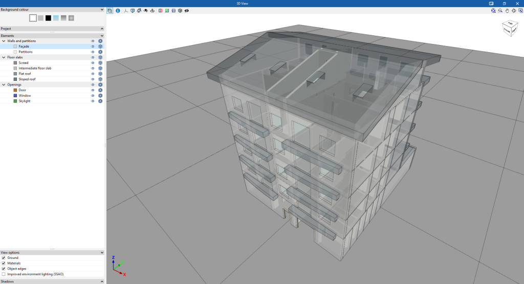
- If an IFC file with the geometry of the building is available, it can be imported into the "3D Model" tab of CYPETHERM LOADS with the "Import IFC" option and, using a wizard, automatically generate the geometry of the following model data: walls, floor slabs, roofs, windows, doors and skylights. The corresponding adjustments can then be made in the "3D model" tab to complete the model.
After creating or importing and adjusting the building geometry in the "3D model" tab, the program generates the thermal model with the corresponding option, thus moving to the "Thermal loads" tab.
Importing BIM models from BIMserver.center and generating the thermal model
If the CYPETHERM LOADS job is linked to a BIM project on the BIMserver.center platform, the following actions can be carried out:
- Importing the model with the geometry of a building. This is used to generate the geometrical information of the thermal model. The following options are available:
- If the model has been designed in CYPE Architecture and shared in BIMserver.center, after going through Open BIM Analytical Model, the analytical model generated by this program can be imported and shared again in BIMserver.center.
- If the model has been designed in IFC Builder and shared in BIMserver.center, the geometric information can be imported without using any intermediate program.
- If the model has been designed in Autodesk Revit, its information must be shared to BIMserver.center using the Open BIM - Revit Plugin. After passing through Open BIM Analytical Model, the analytical model generated by this program can be imported and shared again in BIMserver.center.
- If the model has been designed in CAD/BIM programs such as Allplan, ArchiCAD and others capable of generating a file in IFC format, this file must be incorporated into the BIMserver.center project using IFC Uploader. After going through Open BIM Analytical Model, the analytical model generated by this program can be imported and shared again in BIMserver.center.
- Importing the model with the construction systems of a building. This generates the information related to the building elements of the thermal model. The following options are available:
- Importing construction systems designed in CYPE Construction Systems. The CYPE Construction Systems step is useful if CYPE Architecture, Revit or other CAD/BIM programs have been used to create the geometric model, or if IFC Builder has been used without entering the information relating to the construction systems.
- Importing construction systems designed in IFC Builder.
- Importing the site model. This incorporates information about site elements, such as nearby buildings or other obstacles, which will affect the automatic calculation of shadows on the elements of the CYPETHERM LOADS model. The following options are available:
- Calculating shadows based on the buildings entered in the model designed in Open BIM Site and shared in BIMserver.center. After going through the Open BIM Analytical Model, the analytical model generated by this program can be imported and shared again in BIMserver.center.
- Calculating shadows based on nearby buildings and other obstacles in the model designed in IFC Builder.
- Importing the model with the lighting analysis of the building. This makes it possible to incorporate data on the installed lighting power in the spaces. The following options are among those available:
- Importing the installed lighting power in the model spaces developed in CYPELUX.
If a model is imported from BIMserver.center, there is no need to go through the "3D model" tab of CYPETHERM LOADS: the work in this program will start directly in the "Thermal loads" tab.
Data output
CYPETHERM LOADS provides the following data output options:
- Exporting reports to HTML, DOCX, PDF, RTF and TXT formats.
- Exporting drawings to DXF, DWG and PDF formats.
- Exporting of the information generated with CYPETHERM LOADS to the BIMserver.center platform using IFC formats. The thermal load information generated by CYPETHERM LOADS can be used by the following programs:
- CYPEHVAC
Design and analysis of hydronic, refrigerant and ducted air-conditioning systems. - CYPEHVAC Radiant Floor
Design and analysis of radiant floor heating systems.
- CYPEHVAC
Calculation methods and codes
The program incorporates the following analysis methodology and codes:
- Calculation in accordance with ANSI/ASHRAE/ACCA Standard 183-2007 (RA 2011), ‘Peak Cooling and Heating Load Calculations in Buildings Except Low-Rise Residential Buildings’, which establishes the minimum requirements for any method or procedure used to calculate peak cooling and heating loads.
- Calculation of cooling heat loads according to the ASHRAE radiant time series method.
- Heating loads according to ASHRAE or EN 12831.
- ISO 6946. Building components and building elements. Thermal resistance and thermal transmittance. Calculation methods.
- ISO 13370. Thermal performance of buildings. Heat transfer via the ground. Calculation methods.
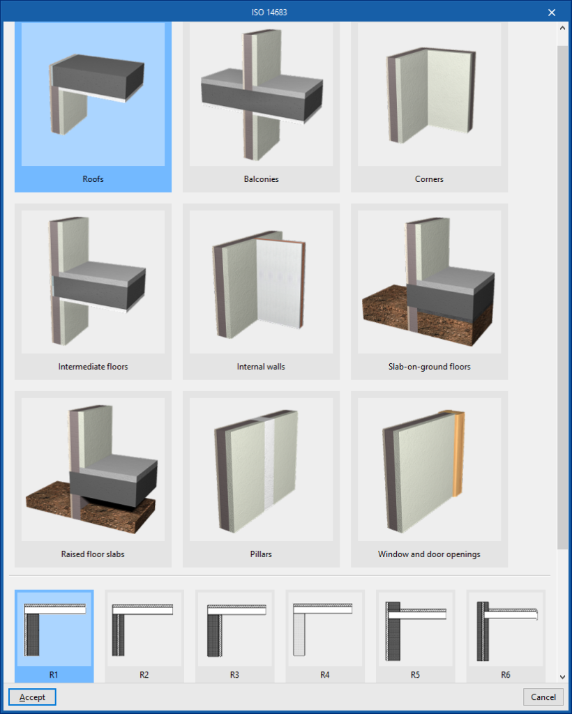
- ISO 14683. Thermal bridges in building construction. Linear thermal transmittance.Simplified methods and default values.
- ISO 10456. Building materials and products. Hygrothermal properties.
- Automatic shadow detection in the calculation model (from the 3D model or BIM models).
- Automatic edge detection (from 3D model or BIM models).
- Management of edges for buildings from BIM models, allowing the generation of thermal bridges with their corresponding transmittances (according to ISO 14683) based on the edges detected, depending on the construction solutions adopted and the description of the building from the point of view of thermal analysis (zoning, description of spaces, etc.) with the possibility of calculation by numerical analysis according to ISO 10211.
Radiant Time Series Method
The Radiant Time Series Method (RTSM), proposed and recommended by the American Society of Heating, Refrigerating and Air-conditioning Engineers (ASHRAE) for the calculation of cooling heat loads and detailed in its "Load Calculation Applications Manual" of 2010, is the most widely used method for the estimation of heat loads.
As a calculation method that separates the contributions of each input, it facilitates the analysis and understanding of the results by the project designer, which together with its accuracy, speed and low computational requirements, makes it a perfect method to improve the design of the building quickly and intuitively.

Work environment
The CYPETHERM LOADS interface presents two tabs at the bottom of the main window with different working environments: "3D model" and "Thermal loads".
"3D model" tab
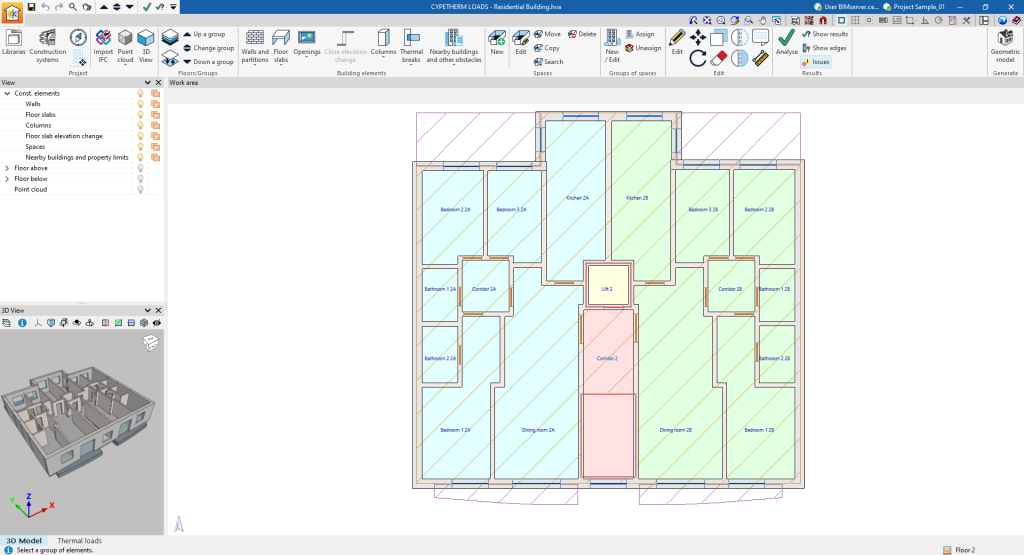
The "3D Model" tab contains the tools for designing the geometric or architectural model of the building. Construction systems can also be defined.
This tab contains features equivalent to the independent program IFC Builder. More information can be found on its detailed information page.
"Thermal loads" tab
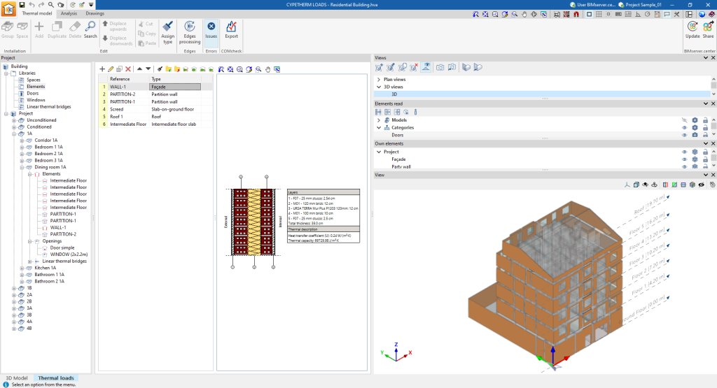
The "Thermal loads" tab contains the tools to adjust the thermal model of the building, perform the thermal load analysis, and obtain its results.
This tab is in turn organised into three other tabs located at the top of the main window:
- "Thermal model" tab
Checks and completes the thermal model of the building to be used in the analysis. The information in this tab can be obtained through an import of BIM models from BIMserver.center or generated from the information entered in the "3D model" tab.
- "Analysis" tab
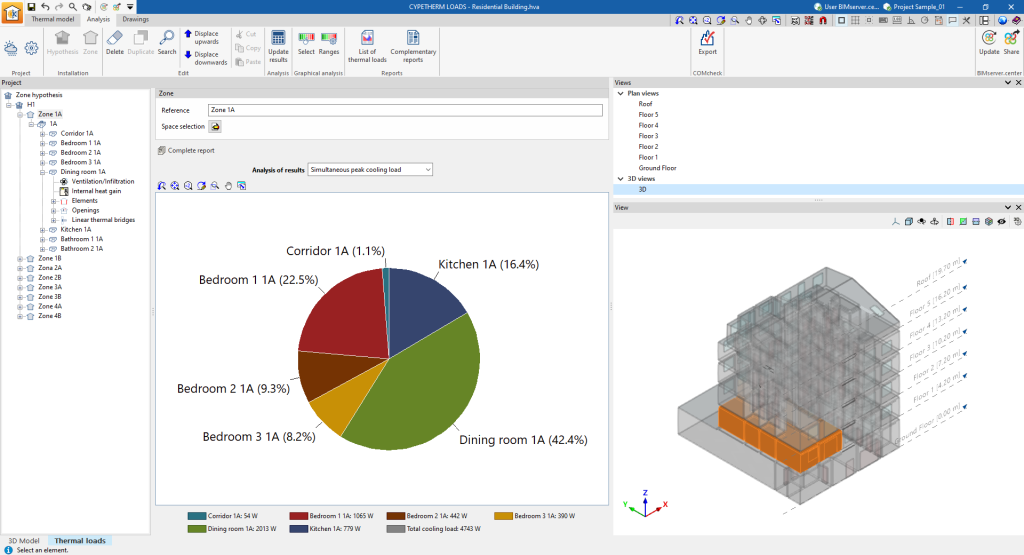
Analyses thermal loads and checks the results obtained through different reports and graphs.
Data input and output sequence for the design and analysis of thermal loads in a building
The analysis of thermal loads in a building can be carried out in the program by means of the following data input and output sequence:
- Creating a new job (from "File", "New").
- (Optional) Linking to BIMserver.center. The building geometry, construction systems and site from the BIM model can be imported.
- (Optional) Defining the geometry of the building and nearby buildings and other obstacles in the "3D model" tab ("Project", "Plans/Groups", "Building elements" and "Spaces" groups), if not imported from the BIM model. The construction systems ("Project" group, "Construction systems") and the groups of spaces ("Groups of spaces" group) can also be defined at this stage. The thermal model is then generated ("Generate" group, "Geometric model").
- Completing the definition of the thermal model in the "Thermal loads" tab in the "Thermal model" tab:
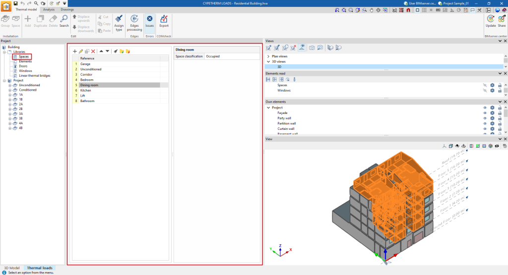
- Defining the characteristics of the spaces by managing their libraries ("Project" panel, "Building", "Libraries", "Spaces").
- (Optional) Defining the characteristics of the construction systems by managing their libraries ("Project", "Building", "Libraries", "Elements"/"Doors"/"Windows"), if the construction systems have not been imported and defined beforehand.
- "Edges processing" option for generating linear thermal bridges.
- In the "Thermal loads" tab of the "Analysis" tab, enter the following data required for the analysis, carry out the analysis and view the results:
- Setting the site data ("Project" group, "Site data"): data import and manual input.
- Setting the analysis options ("Project" group, "Calculation options").
- Defining the zone hypothesis and the zones included in each scenario ("Installation" block, "Scenarios" and "Zone" options).
- Analysing the thermal loads of the building ("Calculation" group, "Update results").
- (Optional) On-screen consultation of reports and graphs of analysis results in the project tree, at the level of hypothesis, zone, space and element ("Project" panel side tree).
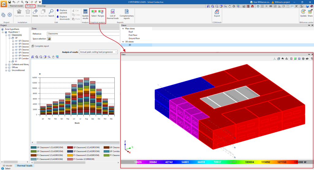
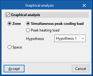
- (Optional) On-screen consultation of the results by means of a graphical analysis ("Graphical analysis" group).
- Obtaining reports (through the options of the ‘Reports’ group and, in the tree of the "Project" panel, the "Complete report" option at the hypothesis or zone levels).
- Generating and obtaining drawings ("Thermal loads" tab, "Drawings" tab).
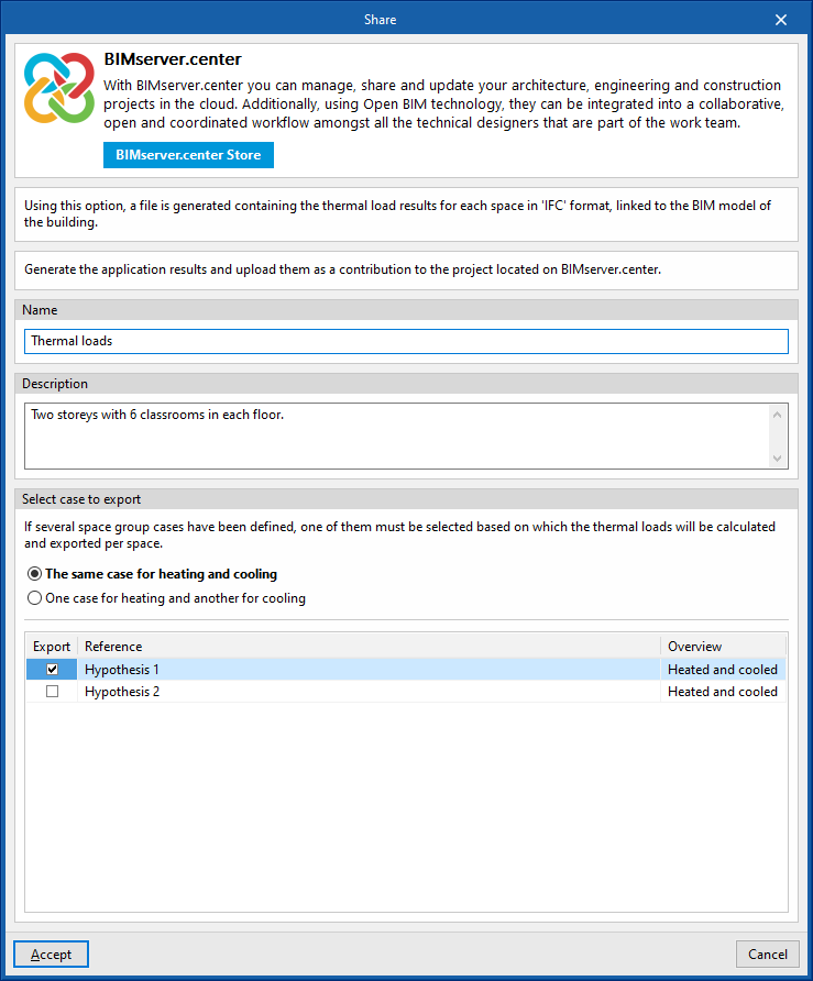
- Exporting to BIMserver.center ("BIMserver.center" group, "Share").
Examples of building models for the analysis of thermal loads
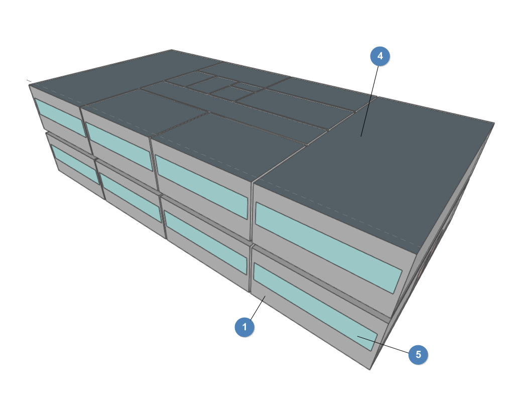
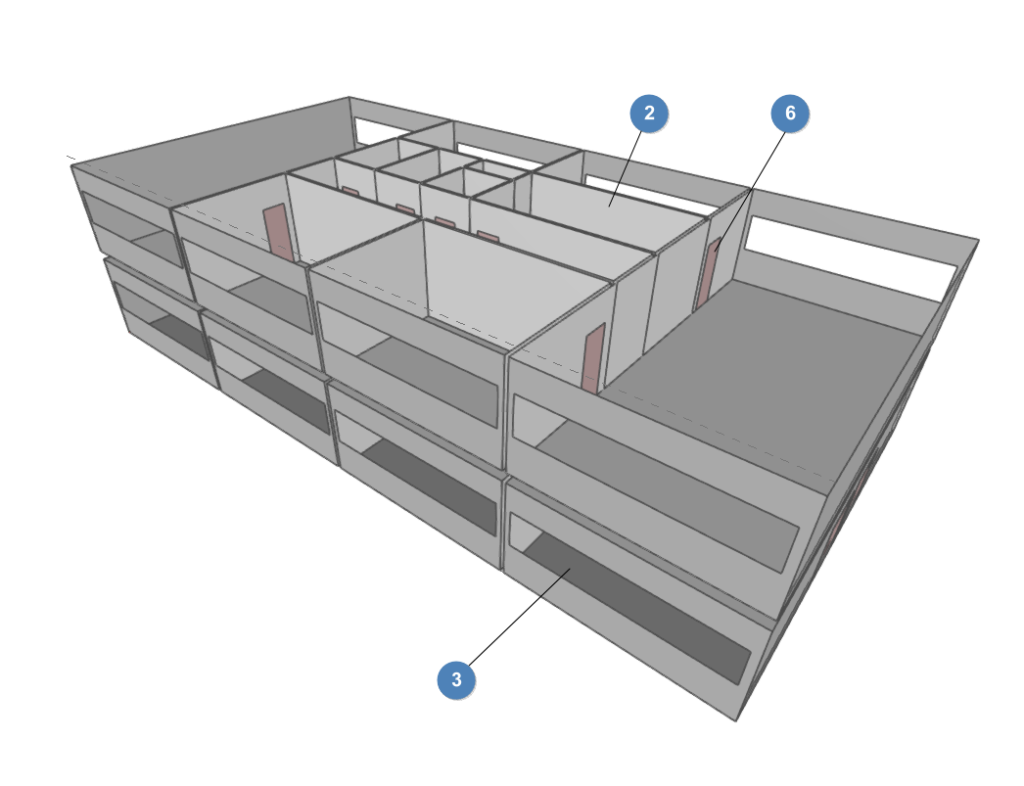
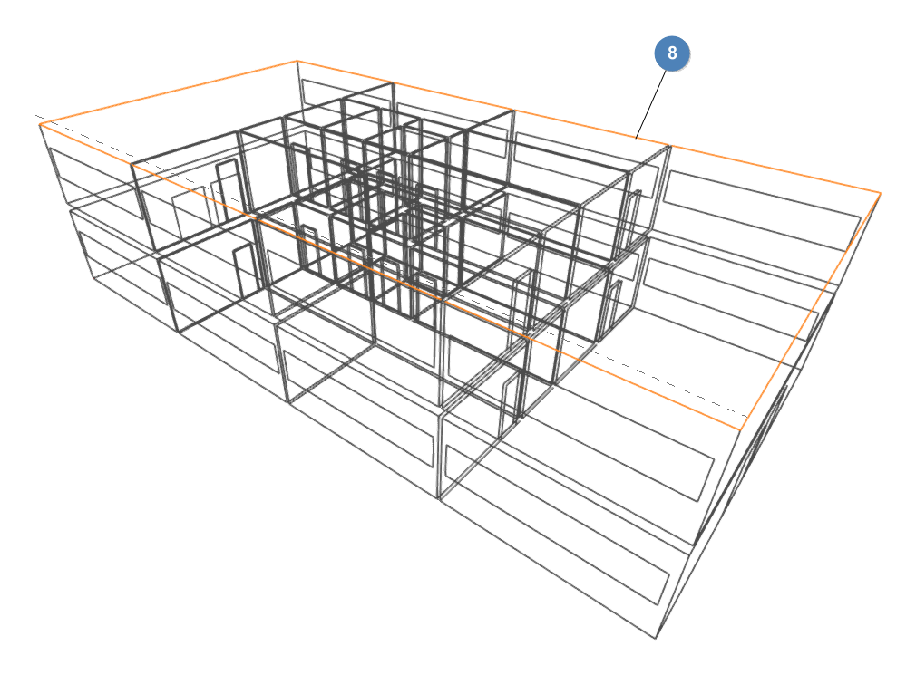
Below is an example of a model of a building that can be developed in the program, indicating the layout of the elements and the options that allow them to be entered in the model, and with which the analysis of thermal loads can be carried out.
Model of a two-storey office building
- External walls
- Entered from the "3D model" tab, "Building elements" group, "Walls and partitions", "External walls".
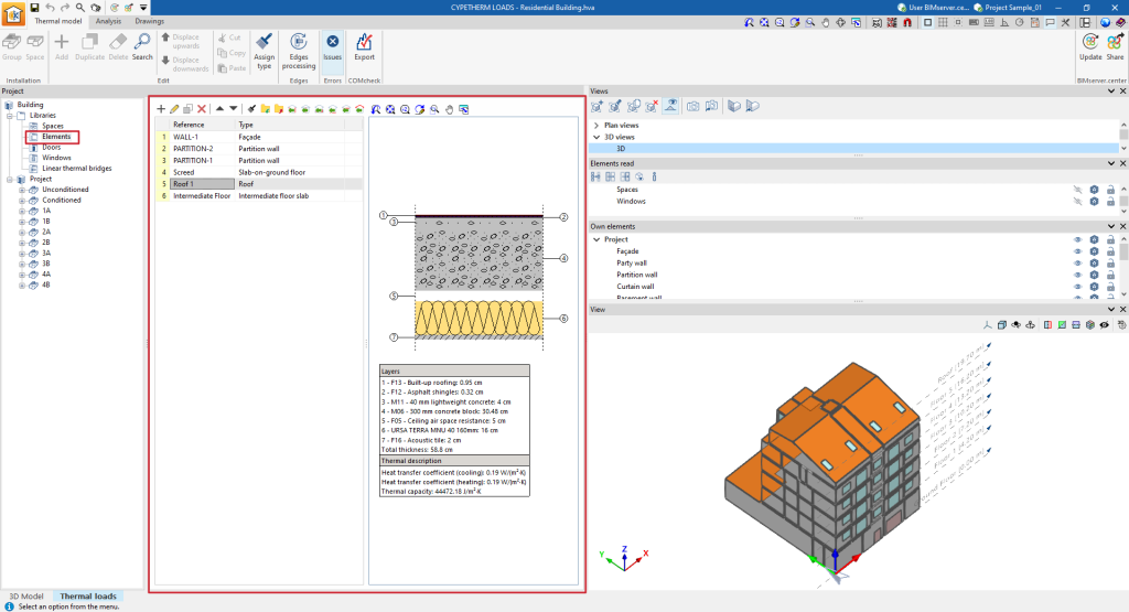
- Defined from the "Thermal loads" tab, "Thermal model", "Project", "Libraries", "Elements".
- Partitions
- Entered from the "3D model" tab, "Building elements" group, "Walls and partitions", "Partition".
- Defined from the "Thermal loads" tab, "Thermal model", "Project", "Libraries", "Elements".
- Screed
- Introducida desde la solapa "Modelo 3D", bloque "Elementos constructivos", "Forjados", "Solera".
- Definida desde la solapa "Cargas térmicas", pestaña "Modelo térmico", panel "Proyecto", árbol "Bibliotecas", "Elementos".
- Roof
- Entered from the "3D model" tab, "Building elements" group, "Floor slabs", "Flat roof".
- Defined from the "Thermal loads" tab, "Thermal model", "Project", "Libraries", "Elements".
- Windows
- Entered from the "3D model" tab, "Building elements" group, "Openings", "Window or glazed opening".
- Defined from the "Thermal loads" tab, "Thermal model", "Project", "Libraries", "Openings".
- Doors
- Entered from the "3D model" tab, "Building elements" group, "Openings", "Door".
- Defined from the "Thermal loads" tab, "Thermal model", "Project", "Libraries", "Openings".
- Spaces
- Entered from the "3D Model" tab, "Spaces" group, "New".
- Defined from the "Thermal loads" tab, "Thermal model" tab, "Project" panel, "Libraries", "Spaces".
- Linear thermal bridges (generated from the "Thermal loads" tab, "Thermal model" tab, "Edges" group, "Edge processing").
Creating a new job, linking to a project and importing data
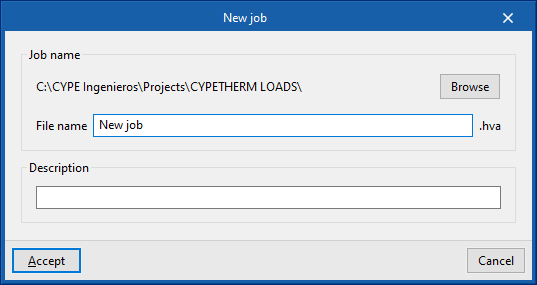
When launching the app and clicking on “New“, a “New job“ can be created. After entering the “File name“ and “Description“, the job can then be integrated into an existing project in BIMserver.center.
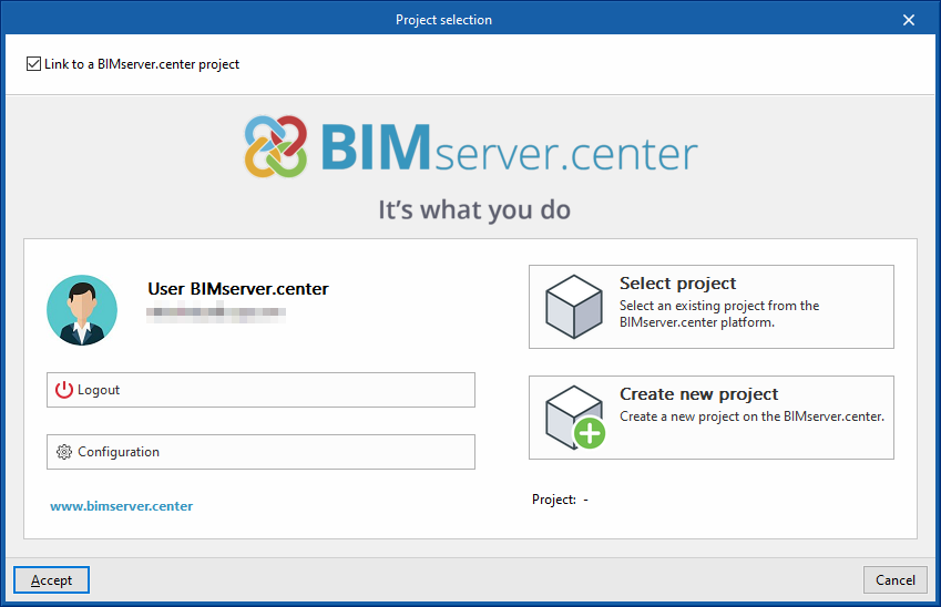
This is done in the "Project selection" window, which has the following options:
- On the left-hand side, users can log in with a BIMserver.center account.
- On the right-hand side, the "Select project" option is used to choose an existing project. There is also the possibility to "Create a new project". In this case, the created project will be visible from BIMserver.centre from that moment on.
- The project can also be starting without being linked to the BIMserver.center platform. To do this, simply uncheck the box at the top left, "Link to a BIMserver.center project".
Once the new job has been created, the program interface is accessed, where the graphic window showing the model or models that have been imported stands out. At any time during the project, files can be shared or imported via the "BIMserver.center" group on the top right-hand side.
Importing BIM models
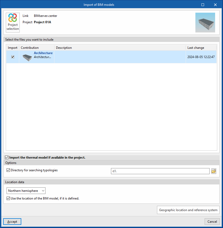
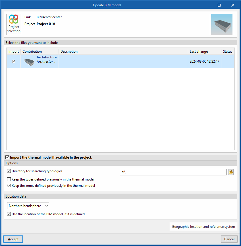
When creating a new job and selecting a project hosted on the BIMserver.center platform from "Select project", the "Import BIM models" window appears, which shows the files contained in that project in IFC format.
The program can include one or more of the existing models in the project. To do this, check the "Import" box and accept it.
The program also offers the following options in this window:
- Import the thermal model if it is available in the project (optional)
By checking this box, the program automatically generates the thermal model during the import in the tab of the same name ("Thermal model") of the "Thermal loads" tab, based on the information available in the BIM model of the project in BIMserver.center, including the architectural geometry and construction systems, if any.- Options
- Directory for searching typologies (optional)
By activating this option, users can select a directory on the disk where the typology library files are stored. This is used to import the typology libraries previously created in other jobs and exported to that directory, and automatically assign them to the spaces, elements and openings of the imported model. To do this, the references of the typologies in the selected directory must coincide with the references of the element types in the imported model.
- Directory for searching typologies (optional)
- Location data
- Northern hemisphere / Southern hemisphere
Selects the hemisphere where the project is located. - Use the location of the BIM model, if it is defined (optional)
Completes the generation of shadows on the elements of the job by collecting the information of the elements of the site (such as nearby buildings or nearby obstacles) that are defined in the BIM model.
- Northern hemisphere / Southern hemisphere
- Options
The 3D view of the program will then display the visualisation of the imported models. Furthermore, if necessary, the program will generate the thermal model and the libraries of elements from the existing data in the project or the selected directory. At this point, it will be possible to start detailing the libraries of types that have not yet been defined to continue working on the model.
Architectural modelling in the "3D model" tab
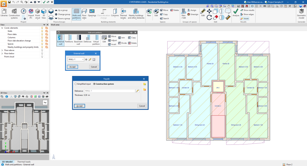
The building geometry can be defined directly in the program using the tools in the "3D model" tab at the bottom of the program's general interface.
This tab is used to configure the project and the floors or groups, to enter the building elements (walls and partitions, floor slabs, openings, etc.) and the spaces, and to define the groups of spaces of the building from scratch, together with nearby buildings and other obstacles, in a work environment identical to that of the independent program IFC Builder.
Here, together with the architectural geometry, it is also possible to define the construction systems associated with the different typologies of the elements entered.
Additionally, in this tab, IFC files can be imported by means of a specific wizard that automatically generates the elements of the 3D model.
More information on the options and features of this environment can be found on the IFC Builder detailed information page.
Generating the thermal model from the 3D model
Once the 3D model has been completed, the "Geometric model" option in the "Generate" group from the top toolbar can be used to generate the thermal model of the building and move to the tab of the same name in the "Thermal loads" tab, which allows work to continue.

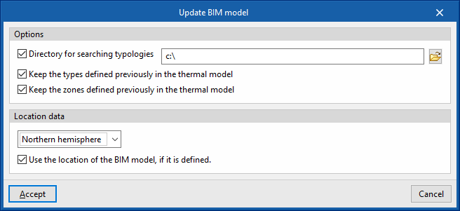
Using this option opens the "Update BIM model" window, with the following options:
- Options
- Directory for searching typologies (optional)
- Keep the types defined previously in the thermal model (optional)
- Keep the zones defined previously in the thermal model (optional)
- Location data
- Northern hemisphere / Southern hemisphere
Selects the hemisphere where the project is located. - Use the location of the BIM model, if it is defined (optional)
Completes the generation of shadows on the elements of the job by collecting the information of the elements of the site (such as nearby buildings or nearby obstacles) that are defined in the BIM model.
- Northern hemisphere / Southern hemisphere
Managing space libraries
The definition of the spaces in the thermal model libraries is necessary to classify them as occupied or unoccupied, air-conditioned or only heated or cooled, as well as to detail the parameters relating to ventilation and internal heat gains, which affect the analysis of thermal loads by the program.
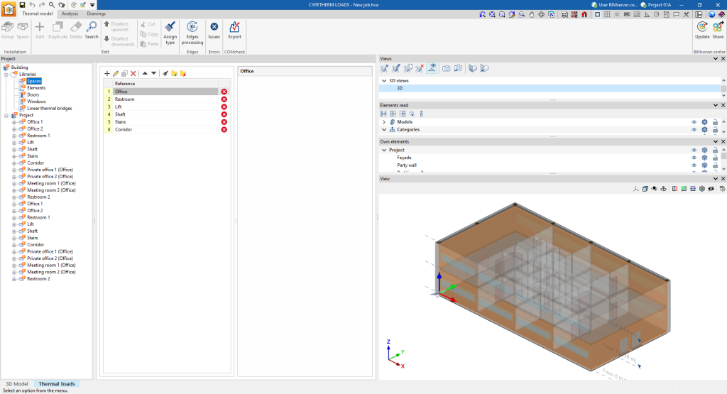
The tools for managing the space libraries of the thermal model are located in the "Thermal loads" tab under the "Thermal model" tab at the bottom and, in the "Project" definition area, in the "Libraries" tree located by default on the left-hand side.
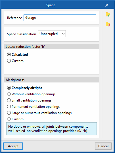
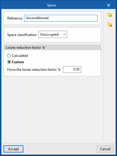
Unoccupied spaces
The definition of the unoccupied spaces is based on the configuration of the following parameters:
- Space classification: Occupied
- Losses reduction factor 'b'
Defines the loss reduction factor ‘b’, which regulates the transmission of heat from occupied spaces to the outside through unoccupied spaces.- Calculated
- Custom
- Force the losses reduction factor 'b'
- Air tightness (if the "Losses reduction factor 'b'" is "Calculated")
The level of airtightness is defined according to the number of renovations/hour of the space:- Completely airtight (0.1/h)
- Without ventilation openings (0.5/h)
- Small ventilation openings (1/h)
- Permanent ventilation openings (3/h)
- Large or numerous ventilation openings (10/h)
- Custom
- Air change rate (h-1)
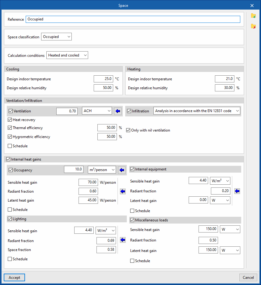
Occupied spaces
The definition of the occupied spaces is based on the configuration of the following parameters:
- Space classification: Occupied
- Calculation conditions (Heated and cooled / Only cooled / Only heated)
- Cooling
- Design indoor temperature (or Maximum indoor comfort temperature, if the space is only heated)
- Design relative humidity
- Heating
- Design indoor temperature (or Maximum indoor comfort temperature, if the space is only cooled)
- Design relative humidity
- Ventilation/Infiltration
- Ventilation (optional)
- Heat recovery (optional)
- Thermal efficiency (optional)
- Hygrometric efficiency (optional)
- Schedule (optional)
- Heat recovery (optional)
- Infiltration (optional)
- By "Flow" / Analysis in accordance with the EN 12831 code
- Only with nil ventilation
- Ventilation (optional)
- Internal heat gains (optional)
- Occupancy (optional)
- Sensible heat gain
- Radiant friction
- Latent heat gain
- Schedule (optional)
- Internal equipment (optional)
- Sensible heat gain
- Radiant friction
- Latent heat gain
- Schedule (optional)
- Lighting (optional)
- Sensible heat gain
- Radiant friction
- Latent heat gain
- Schedule (optional)
- Miscellaneous loads (optional)
- Sensible heat gain
- Radiant friction
- Latent heat gain
- Schedule (optional)
- Occupancy (optional)
Defining schedules
Schedules are used to define the percentage of use of the spaces over the hours of the day and months of the year, both for ventilation and for internal heat gains such as occupancy, lighting, internal equipment and other loads.
The schedules can be edited in the space libraries of the "Thermal model" tab, by checking the corresponding boxes in the "Ventilation/Infiltration" and "Internal heat gains" sections in the editing window of each space type
If no schedule is defined, the program will assume 100 % usage every hour of every day of the year.
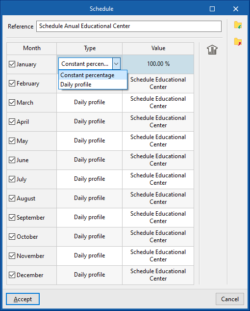
In the editing window of each schedule section, the program can modify the following data:
- Reference
Schedule reference. - Month / Type / Value (optional)
For each month, a constant use percentage can be defined or a daily profile can be selected, which represents a variable use percentage.- Constant percentage
On the right-hand side, the value of the constant percentage of use must be entered. - Daily profile
A previously created daily profile must be selected in the "Available daily profiles" section, accessible by clicking on the button in the right-hand column.
- Constant percentage
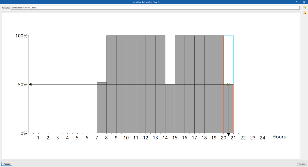
Available daily profiles
This section is used to define a daily schedule, indicating a use percentage between 0 and 100 % for each of the 24 hours of the day. To do this, after creating or editing the daily usage profile, in the editing window that appears, click on the corresponding height on the graph to define the desired use percentage for each hour.
Managing building element libraries
The definition of building elements in the thermal model libraries is necessary to detail the data related to their thermal behaviour, including the possibility of specifying the composition of material layers and the technical characteristics of each of them, such as thermal conductivity or thermal resistance. This data can be entered manually or based on different catalogues and reference standards with predefined materials and will affect the thermal load analysis carried out by the program.
The management tools for the libraries of building elements of the thermal model are located in the lower tab "Thermal loads", in the upper tab "Thermal model" and, in the "Project" definition area, in the "Libraries" tree located by default on the left-hand side.
Elements library
General definition of building elements
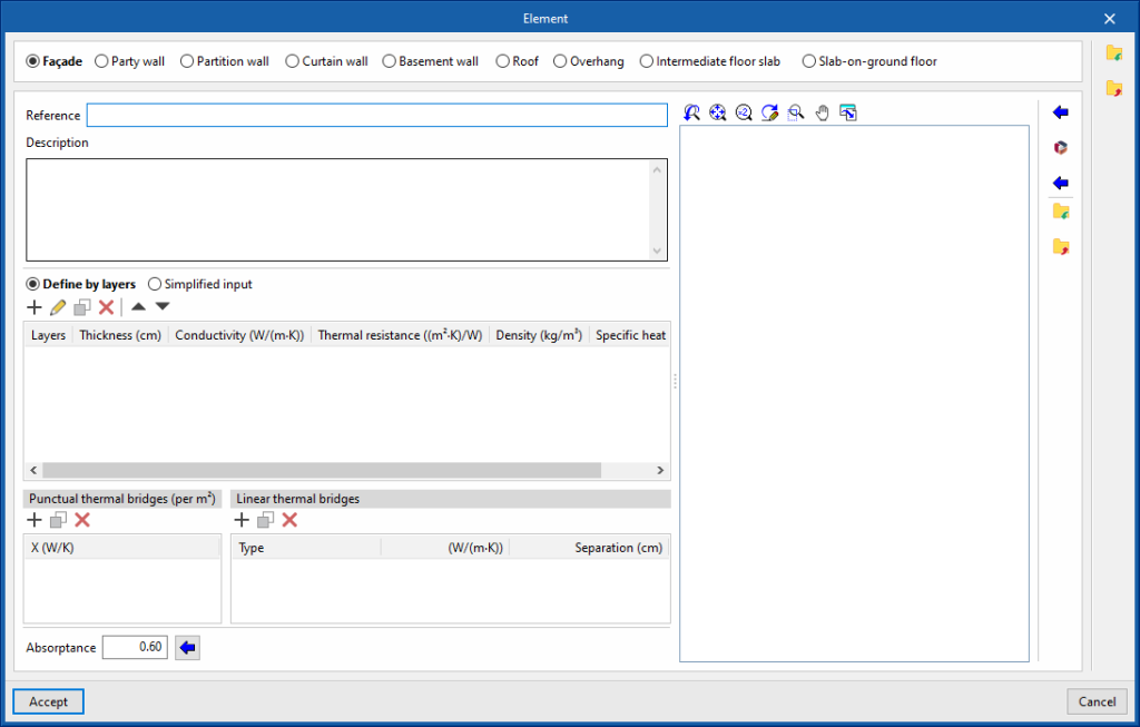
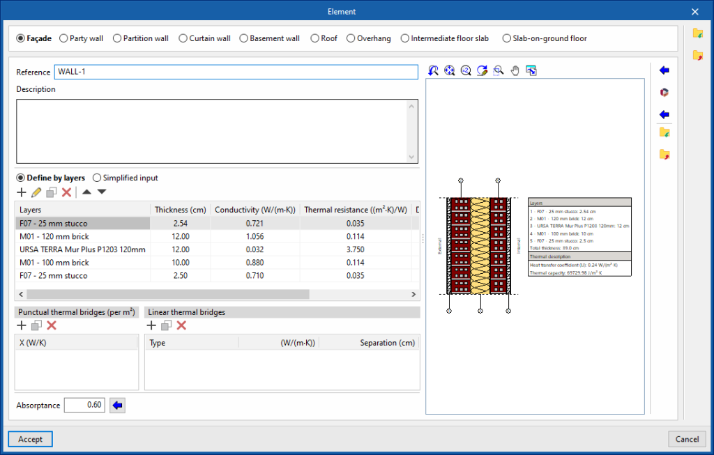
When adding or editing an element type in the library, the following parameters must be configured:
- Type of element (Façade / Party wall / Partition wall / Curtain wall / Basement wall / Roof / Overhang / Intermediate floor slab / Screed)
- Reference
- Description
- Define by layers / Simplified input
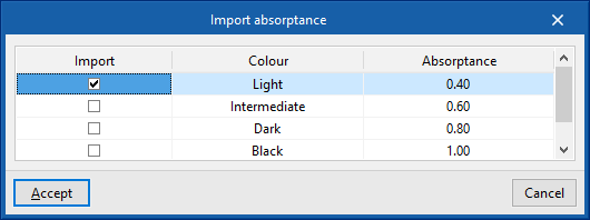
Specifies whether the thermal characteristics of the element are defined by entering the data for each of the component material layers or by a simplified definition. - Absorptance (in elements such as "Façade", "Party wall", "Partition wall", "Roof", "Overhang", or "Intermediate floor slabs")
The absorption fluctuates between 0 and 1. The value can be imported with the wizard available on the right:- Import absorptance
The value of this coefficient is lower on light surfaces, and higher on dark surfaces.
- Import absorptance
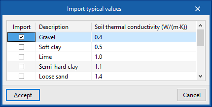
- Soil thermal conductivity (in "Basement wall" or "Screed" type elements)
The conductivity of the soil varies according to its type. The value can be imported with the wizard available on the right:- Importing the thermal conductivity according to the type of soil
The lowest values correspond to gravels and silts; sands provide intermediate values, while rock provides higher values.
- Importing the thermal conductivity according to the type of soil
Additionally, the options in the right-hand column of the "Element" window allow the import of complete building systems from catalogues and databases such as the Open BIM Database.
Defining material layers
If the element is defined by layers, the program offers a table where the material layers of the element can be added, edited, copied, deleted or reordered:
- Define by layers
- Layers
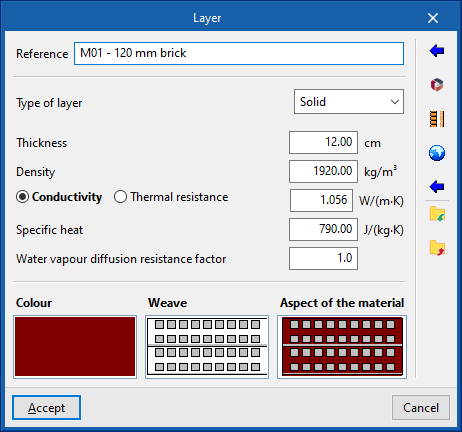
When entering a material layer, the following parameters must be specified:- Reference
- Type of layer
A choice must be made as to whether the coating is solid, an air cavity or a vapour barrier.- Solid
- Thickness
- Density
- Conductivity / Thermal resistance
- Specific heat
- Water vapour diffusion resistance factor
- Air cavity
- Thickness
- Thermal resistance
- Vapour barrier
- Equivalent air thickness
- Solid
- Colour / Weave / Aspect of the material
Adjusts the graphical representation of the layer material.
- Layers
- Importing data
The options in the right column of the "Layer" window allow the automatic import of material data from information provided by different catalogues and standards:- Open BIM Database manufacturer materials
- Open BIM Database catalogue management
- HULC library materials
- Air chambers described in UNE-EN ISO 6946
- Materials described in UNE-EN ISO 10456
- Materials described in EN ISO 10456
- Representative materials (2013 ASHRAE Handbook - Fundamentals)
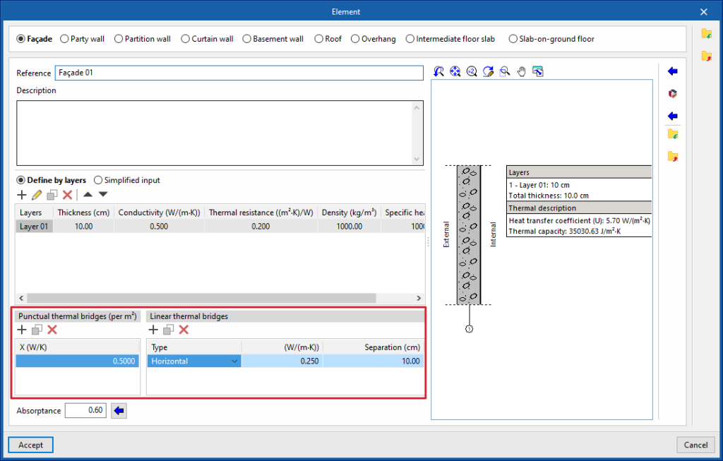
- Punctual thermal bridges
This table is used to declare the existence of point thermal bridges for each surface unit of the element, and their point thermal transmittance value (W/K).
- Linear thermal bridges
This table is used to declare the existence of linear thermal bridges along the surface of the element, in horizontal or vertical direction, and their linear thermal transmittance value (W/(m-K)).
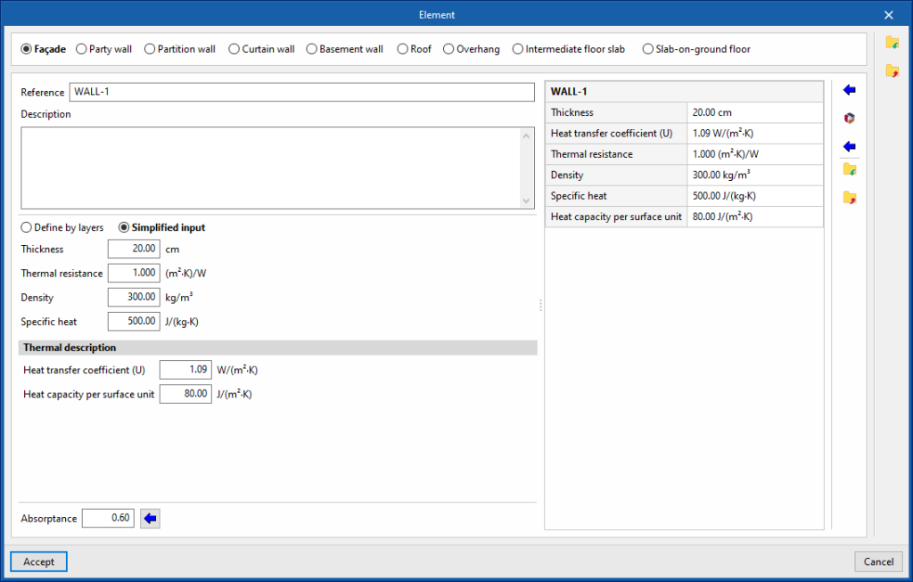
Simplified input
The simplified definition of the element type involves entering its global properties. This is useful if the layer-by-layer data is unknown, if these properties are available or if they have been analysed outside the program.
- Simplified input
- Thickness
- Thermal resistance
- Density
- Specific heat
- Thermal description
- Heat transfer coefficient
- Heat capacity per surface unit
Specific options when defining screeds and raised floor slabs
"Screed" type elements define the following characteristics.
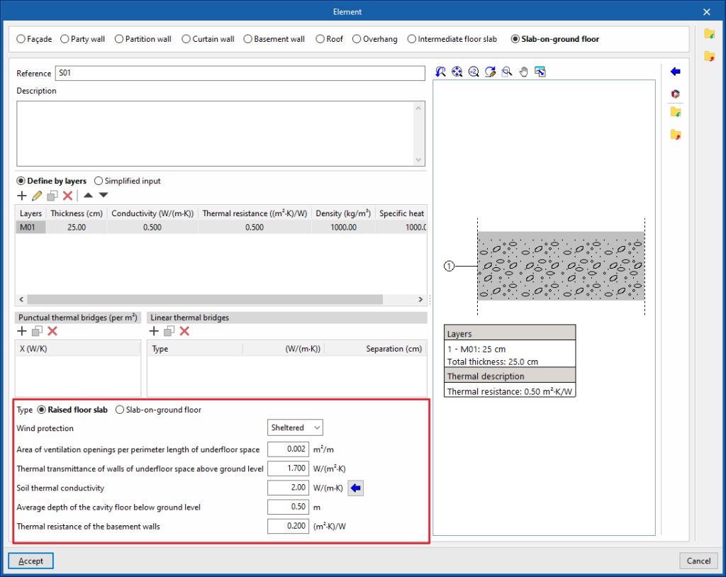
Raised floor slab
Raised floor slabs are defined in the program as a specific type of floor slab. By selecting "Raised floor slab", the program allows users to enter the information about the cavity under the slab and other data such as the following:
- Wind protection (Sheltered / Medium / Exposed)
- Area of ventilation openings per perimeter length of underfloor space
- Thermal transmittance of walls of underfloor space above ground level
- Soil thermal conductivity
- Average depth of the cavity floor below ground level
- Thermal resistance of the basement walls
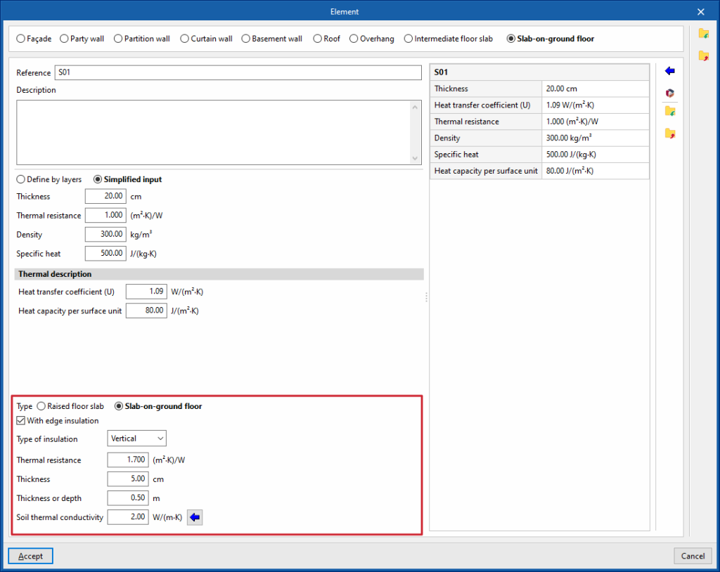
Screed
In the case of screeds alone, peripheral insulation can be added and its characteristics can be defined:
- With edge insulation (optional)
- Type of insulation (Vertical / Horizontal)
- Thermal resistance
- Thickness
- Thickness or depth
- Soil thermal conductivity
- Importing the thermal conductivity according to the type of soil
Specific options when defining curtain walls
"Curtain wall" type elements define the following characteristics:
- Reference
- "Glazed fraction" tab
- Thermal transmittance (U)
- Solar factor
- "Opaque fraction" tab (optional)
- Thermal transmittance (U)
- Opening opaque fraction
This parameter is used to define the proportion of opaque elements covering the total surface of the curtain wall, in percentage. - Absorptance
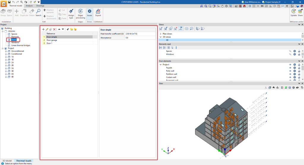
Door library
Like the libraries of the other building elements, the door library can be accessed using the default tree on the left-hand side.
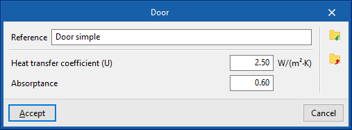
Each door typology entered requires the definition of the following characteristics:
- Reference
- Heat transfer coefficient
- Absorptance
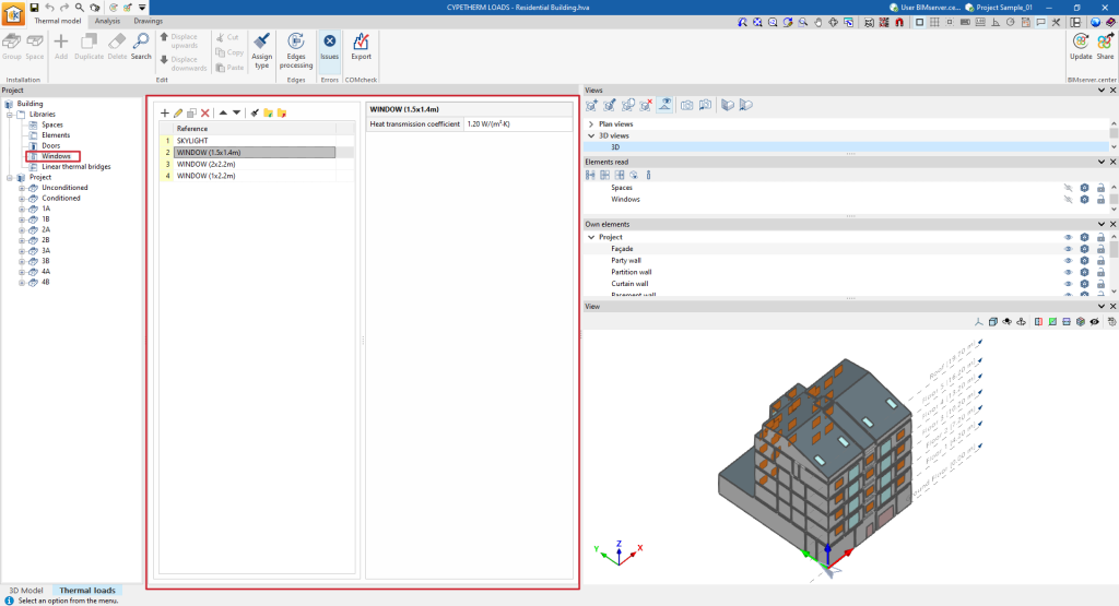
Window library
The window library can also be accessed using the default tree on the left-hand side.
When creating or editing a window type, the data corresponding to its glazing fraction and, optionally, the characteristics of its opaque fraction can be defined, as well as the adjustment of parameters related to its external and internal shading.
- Reference
Opening reference.
- "Glazed fraction" tab
Defines the glazing data of the opening.- Heat transmission coefficient
Heat transmission coefficient of the glazing fraction of the opening.- Simplified input
This option is used to directly enter the heat transmission coefficient of the glazing fraction:- U
- Detailed input
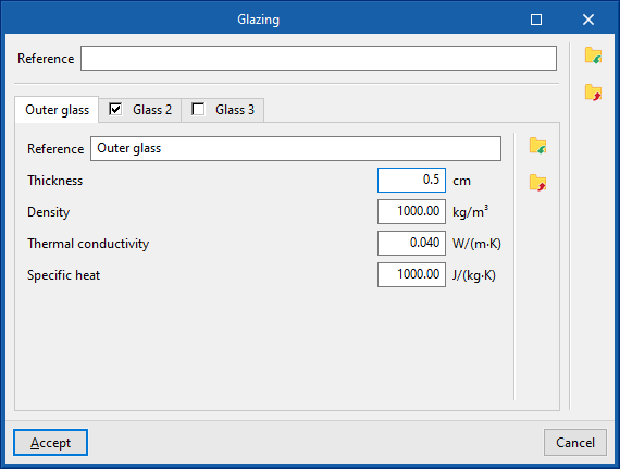
If a detailed definition of the heat transmission coefficient is used, the details of the external glazing and, if available, of the second and third panes, in the case of double or triple glazing, must be given:- "Outer glass" tab
- Thickness
- Density
- Thermal conductivity
- Specific heat
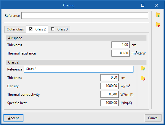
- "Glass 2" tab (optional)
- Air space
- Thickness
- Thermal resistance
- Glass 2
- Thickness
- Density
- Thermal conductivity
- Specific heat
- Air space
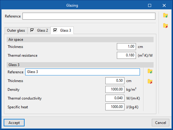
- "Glass 3" tab (optional)
- Air space
- Thickness
- Thermal resistance
- Glass 3
- Thickness
- Density
- Thermal conductivity
- Specific heat
- Air space
- "Outer glass" tab
- Simplified input
- Solar factor of the glass, SHGC
- Simplified input
The solar factor of the glass can be entered, indicating its normal incidence value.- Normal incidence
- Detailed input
The solar factor can be detailed by entering its values according to the angle of incidence.- Normal incidence
- 20º
- 40º
- 60º
- 80º
- Diffuse
- Simplified input
- Importing data from Open BIM Database
- Heat transmission coefficient
- "Opaque fraction" tab (optional)
Defines the data of the opaque part of the opening.- Opening opaque fraction
Fraction of the frame, or area of the opening covered by opaque elements belonging to the frame. It is defined as a percentage of one. - Heat transmission coefficient
Heat transmission coefficient of the glazing fraction of the opening. - Absorptance
- Opening opaque fraction
- "External shading" tab (optional)
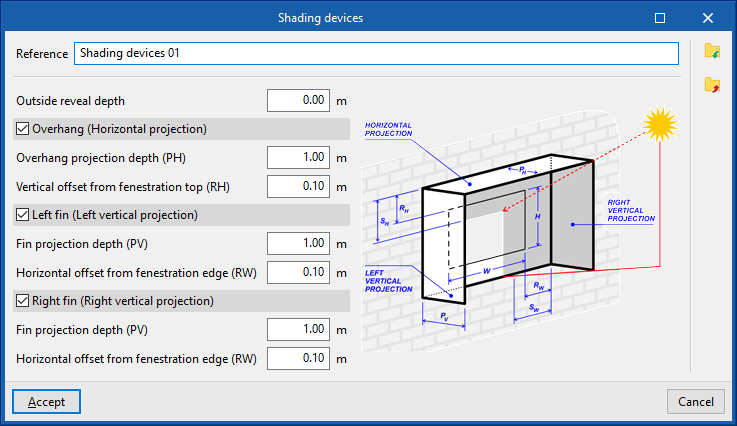
Simulates the effect of external shading of recesses, window overhangs or side projections if they have not been defined in the geometrical model.- Shading devices
- Reference
- Outside reveal depth
- Overhang (Horizontal projection) (optional)
- Overhang projection depth (PH)
- Vertical offset from fenestration top (RH)
- Left fin (Left vertical projection) (optional)
- Fin projection depth (PV)
- Horizontal offset from fenestration edge (RW)
- Right fin (Right vertical projection) (optional)
- Fin projection depth (PV)
- Horizontal offset from fenestration edge (RW)
- Opening height
- Opening width
- Shading devices
The options for defining the external shading of windows allow this data to be entered in a specific way if it cannot be obtained from these other sources of information.
Managing linear thermal bridge libraries
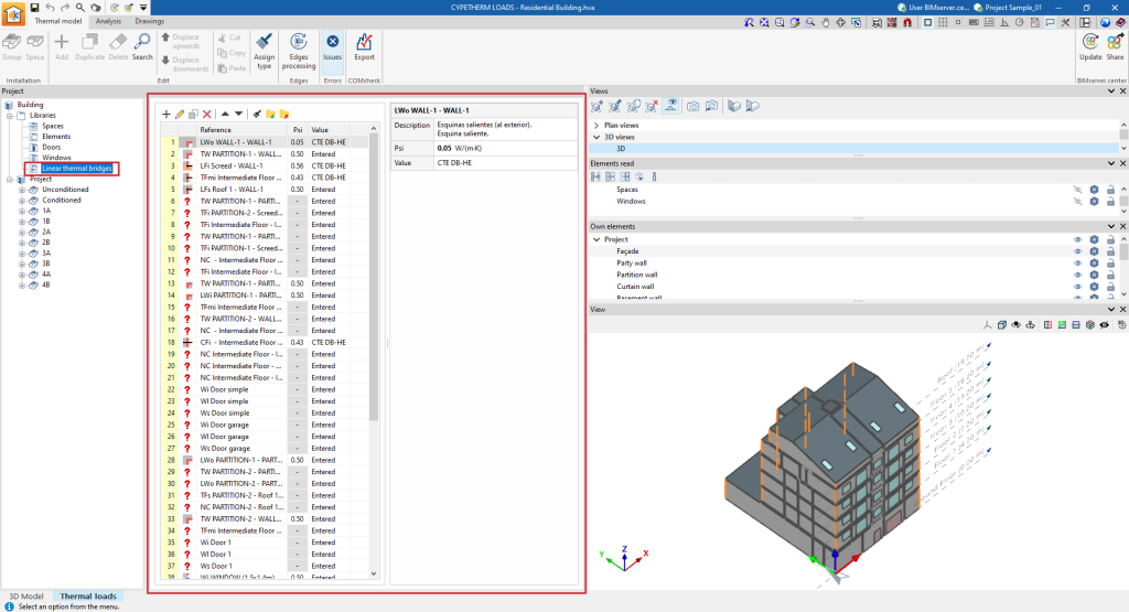
Defining linear thermal bridges in the thermal model libraries allows users to detail their data, such as linear thermal transmittance. This data can be entered manually, imported from reference standard catalogues, or calculated using a linear finite element calculation model and will affect the thermal load analysis performed by the program.
The tools for managing the linear thermal bridge libraries in the thermal model of the building are located in the lower tab "Thermal loads", in the upper tab "Thermal model" and, in the "Project" definition area, in the "Libraries" tree located by default on the left-hand side.
The "Edge processing" option in the top toolbar is then used to edit and adjust the thermal bridges of the model as a whole. This way, the program automatically modifies the data of the thermal bridge types according to the configuration parameters of the edge processing.
However, a particular type of bridge can be edited or modified on an ad hoc basis using the options discussed in this section.
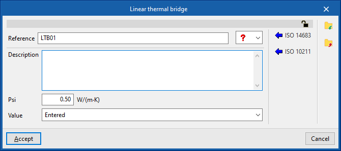
Linear thermal bridge library
When creating or editing a thermal bridge type, the program offers the possibility to configure the following parameters:
- Reference
- Type
The following types are available:- Slab-on-ground floor
- Front of the slab
- Outgoing corner
- Incoming corner
- Windowsill
- Lintel
- Jambs
- Description
- Psi (W/(m·K))
Linear thermal transmittance. - Value (Not defined / Entered / ISO 14683 / ISO 10211)
Origin of the value.
Automated data import
Thermal bridging data can be imported automatically using the following standards and methods:
- ISO 10211
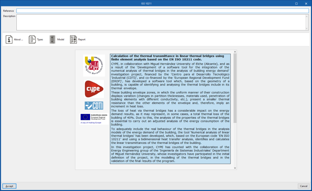
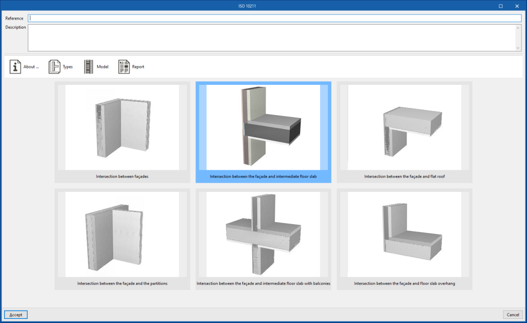
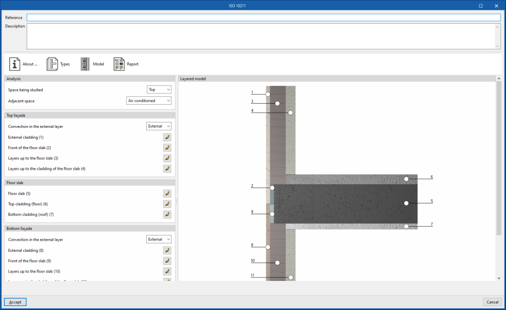
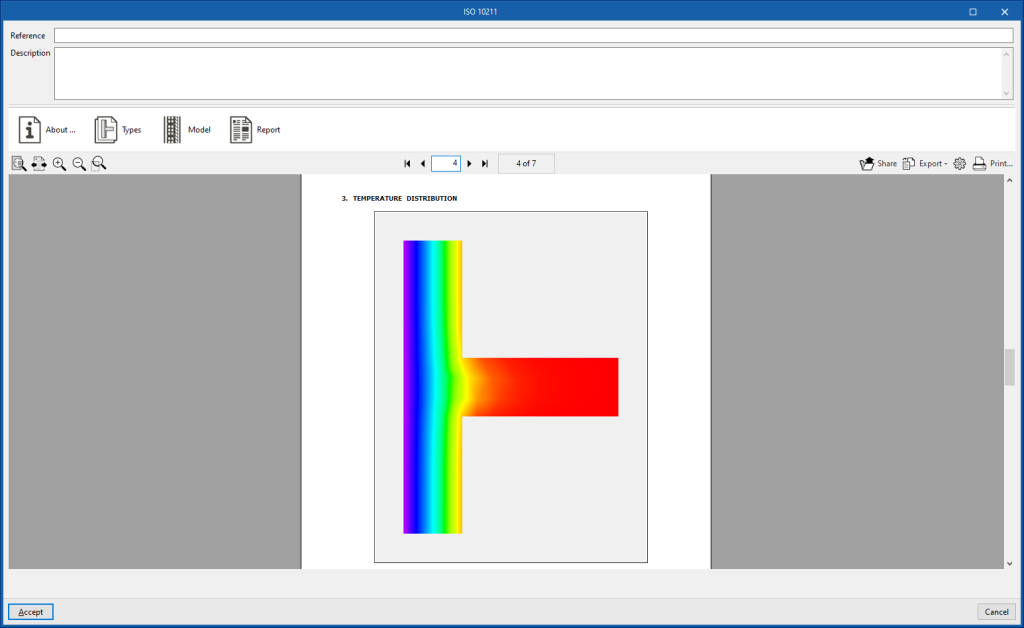
The thermal transmittance of linear thermal bridges can be determined using a finite element analysis based on EN ISO 10211. This method is equivalent to that used by independent programs such as CYPETHERM BRIDGES. The program displays a wizard with the following tabs, which show the following:- About…
Information text on the analysis method used and its implementation in the program. - Types
Selects the type of thermal bridge. - Model
Details the thermal bridge model by defining the layers of material located in each of the positions indicated in the graph. - Report
Report on the analysis of the linear thermal transmittance of the thermal bridge using the finite element analysis proposed in the indicated code.
- About…
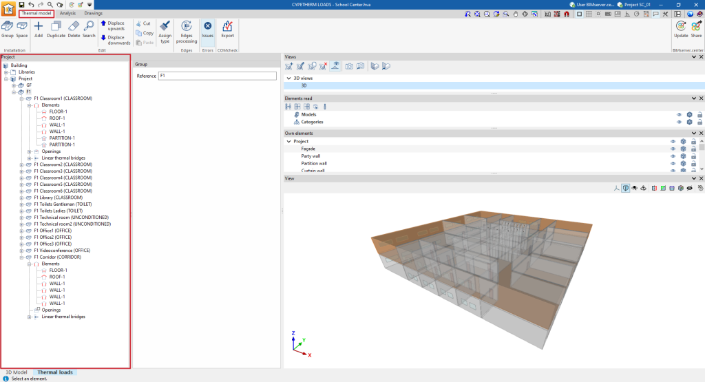
Tree of project elements in the thermal model
The project element tree describes the structure and organisation of all the elements that make up the thermal model of the building, which will be used in the thermal load analysis and incorporates their geometrical data.
The management of elements of the building thermal model is carried out in the lower tab "Thermal loads", within the upper tab "Thermal model" and, in the "Project" definition area, in the "Project" tree located by default on the left-hand side.
The parameters of the elements arranged in this tree, including the spaces, building elements and linear thermal bridges, can be imported from the information of the different types of elements previously created in the libraries.
Generating the thermal model
The thermal model of the building can be generated in several ways:
- If the building has been drawn directly in the "3D model" tab, by clicking on the "Thermal model" option, the program switches to the "Thermal loads" tab and generates the thermal model of the building in this tab, including the tree of project elements.
- If the building has been drawn in other applications and the model information has been shared to a BIMserver.center project, the program can import it and generate the thermal model in the process of creating a new building or updating the project information.
Tools in "Installation": groups and spaces
The "Installation" group in the top toolbar can be used to manually enter groups and spaces. These elements are added to the project tree under the selected level. Thus, if the "Project" level is selected, the program creates a group or a space at the next level down.

These options are equivalent to the following, which appear in the context menu that appears when right-clicking on a level in the element tree: "Add (Groups)" and "Add (Spaces)".
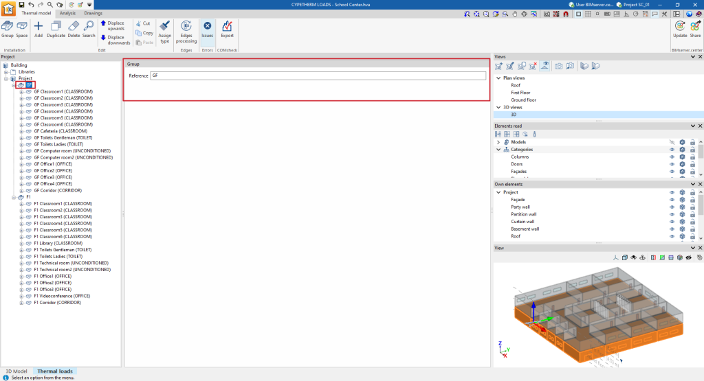
Groups
The "Group" option allows users to add a group in the project tree. Groups are groupings of spaces or other groups and the only data required is their reference:
- Reference
Group reference.
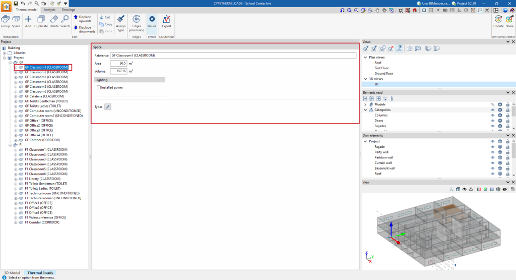
Spaces
The "Spaces" option allows you to add a space in the project tree, either within a group or under the "Project" level. When adding a space, the program requires the following characteristics to be defined:
- Reference
Space reference. - Area
Floor area of the space. - Volume
Air volume of the space. - Lighting
The value of installed lighting power in each space can be taken from the BIM lighting design model included in the BIMserver.center project.- Installed power (optional)
The value of installed lighting power in each space can be taken from the BIM lighting design model included in the BIMserver.center project.
- Installed power (optional)
- Type
Directly edits of the parameters describing the space. A type already configured in the space libraries can be loaded using the button in the top right corner, which opens the "Import" window, where the desired type can be selected.
Elements
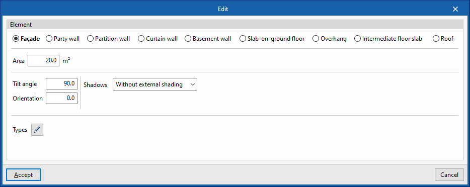
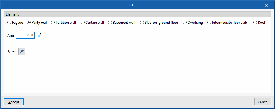
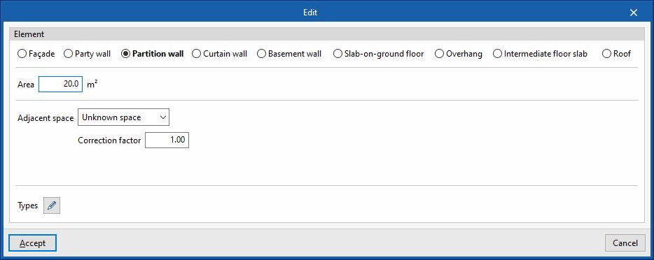
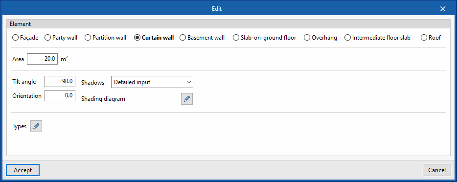
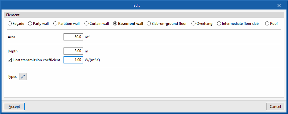
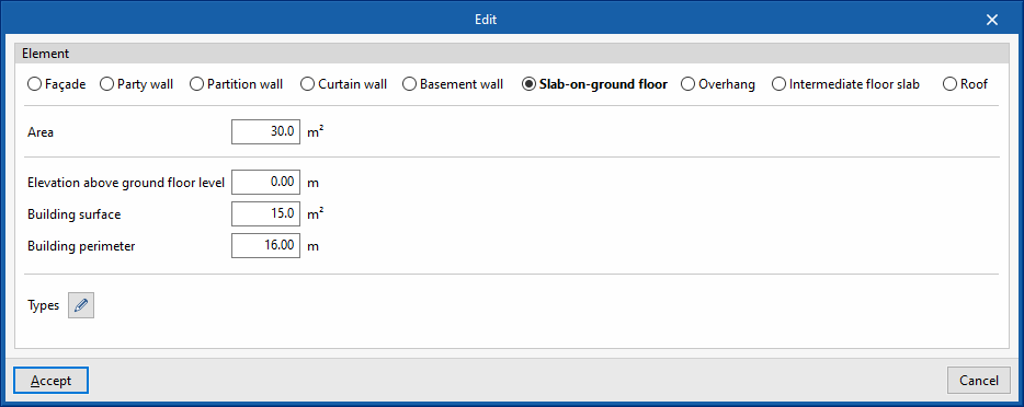
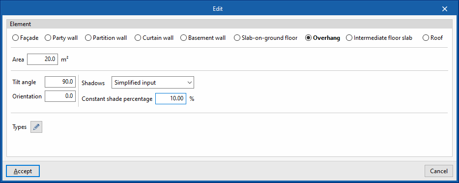
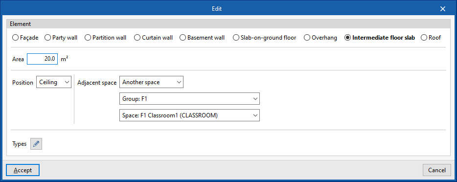
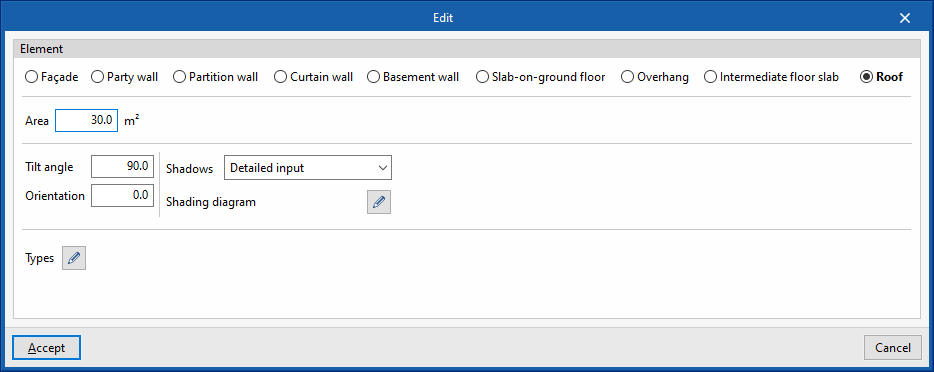
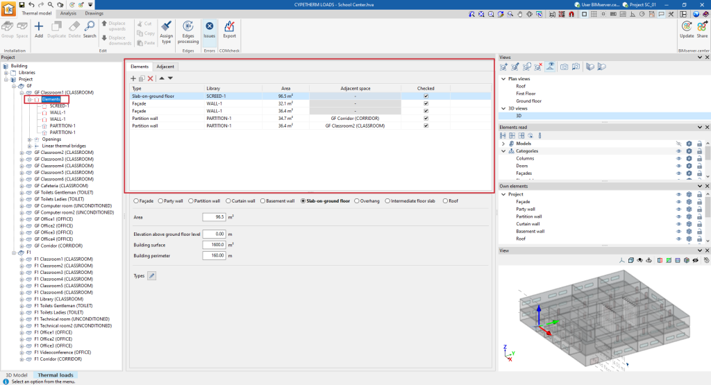
The elements are each of the façades, party walls, partition walls, curtain walls, basement walls, slab-on-ground floors, overhangs, floor slabs between floors and roofs that make up the geometry of a space.
To add elements, the "Add (Elements)" option in the context menu that appears when right-clicking on an ‘Elements’ level, located below the level of any space, can be used.
The data required by the program when entering each of the above-mentioned types of elements are as follows:
- Façade
- Area
- Tilt angle
- Orientation
- Shadows
- Without external shading
- Simplified input
- Constant shade percentage
- Detailed input
- Shading diagram
- Types
- Partition wall
- Area
- Adjacent space
- Unknown space
- Correction factor
- Adjacent space
- Select space
- Adiabatic element
- Unknown space
- Types
- Curtain wall
- Area
- Tilt angle
- Orientation
- Shadows
- Without external shading
- Simplified input
- Constant shade percentage
- Detailed input
- Shading diagram
- Types
- Slab-on-ground floor
- Area
- Elevation above ground floor level
- Building surface
- Building perimeter
- Types
- Overhang
- Area
- Tilt angle
- Orientation
- Shadows
- Without external shading
- Simplified input
- Constant shade percentage
- Detailed input
- Shading diagram
- Types
- Intermediate floor slab
- Area
- Position (Floor/Roof)
- Adjacent space
- Unknown space
- Correction factor
- Adjacent space
- Select space
- Adiabatic element
- Unknown space
- Types
- Roof
- Area
- Tilt angle
- Orientation
- Shadows
- Without external shading
- Simplified input
- Constant shade percentage
- Detailed input
- Shading diagram
- Types
The elements in each space are listed in a table with the following information:
- Type
Type of element. - Library
Reference of the assigned library type. - Area
Element area. - Adjacent space
Reference of the adjacent space (in partition walls and slabs between floors). - Checked
By ticking the box in this column, the item is indicated as checked. - Warnings
Warnings on each element.
Openings
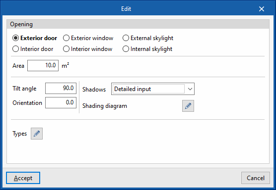
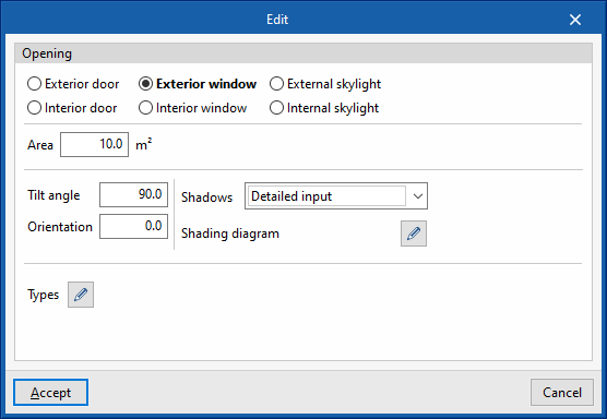
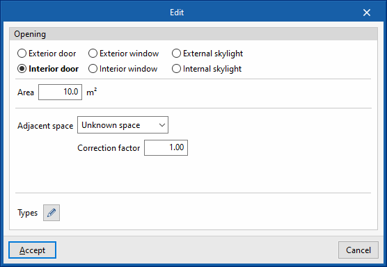
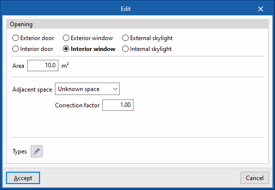
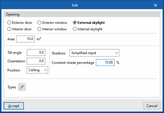
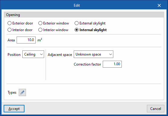
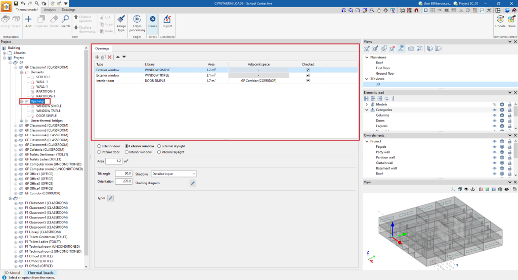
The openings that define the program in each space include doors, windows and skylights, both exterior and interior.
To add openings, you can use the "Add (Openings)" option in the context menu that appears when you right-click on an "Openings" level, located below the level of any space.
The data required by the program when entering each of the above-mentioned opening types are as follows:
- Exterior door / Exterior window
- Area
- Tilt angle
- Orientation
- Shadows
- Without external shading
- Simplified input
- Constant shade percentage
- Detailed input
- Shading diagram
- Types
- Interior door / Interior window
- Area
- Adjacent space
- Unknown space
- Correction factor
- Adjacent space
- Select space
- Adiabatic element
- Unknown space
- Types
- External skylight
- Area
- Tilt angle
- Orientation
- Position /Floor / Roof)
- Shadows
- Without external shading
- Simplified input
- Constant shade percentage
- Detailed input
- Shading diagram
- Types
- Internal skylight
- Area
- Position (Floor / Roof)
- Adjacent space
- Unknown space
- Correction factor
- Adjacent space
- Select space
- Adiabatic element
- Unknown space
- Types
The openings in each space are listed in a table with the following information:
- Type
Type of openings. - Library
Reference of the assigned library type. - Area
Opening area. - Recinto colindante
Reference of the adjacent space (in interior openings). - By ticking the box in this column, it is indicated that the opening is checked.
- Warnings
Warnings on each opening.
Linear thermal bridges
El programa permite definir los puentes térmicos lineales asociados a cada recinto.
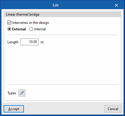
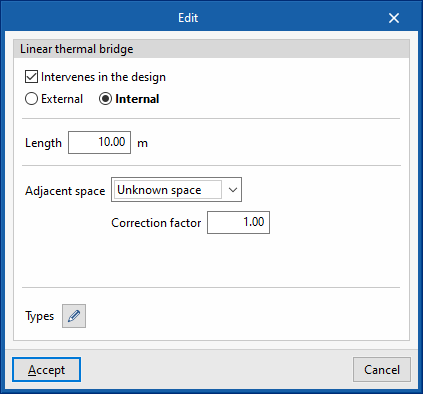
To add openings, the "Add (Linear thermal bridges)" option can be used from the context menu that appears when right-clicking on a "Linear thermal bridges" level, located below the level of any space.
The data required by the program when entering the individual linear thermal bridges is as follows:
- Linear thermal bridges
- Intervenes in the design (optional)
- External / Internal
- Adjacent space
- Unknown space
- Correction factor
- Adjacent space
- Select space
- Adiabatic element
- Unknown space
- Length
- Types
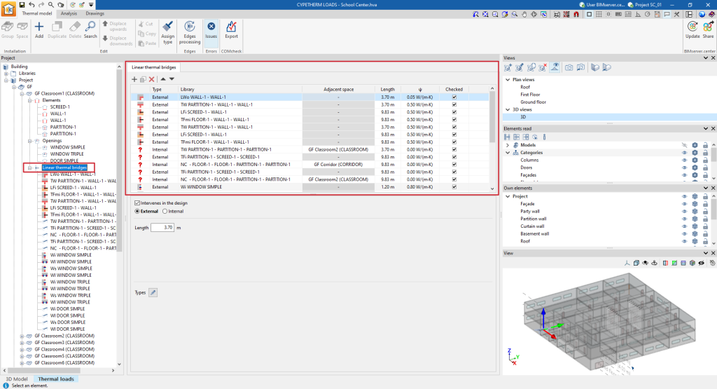
The linear thermal bridges of each space are listed in a table with the following information:
- Type
Linear thermal bridge type (External / Internal). - Library
Reference of the assigned library type. - Adjacent space
Reference of the adjacent space (in interior linear thermal bridges). - Length
Linear thermal bridge length. - ψ
Linear thermal transmittance. - Checked
By ticking the box in this column, it is indicated that the linear thermal bridge is checked. - Warnings
Warnings on each linear thermal bridge.
Tools in the "Edit" group
The following tools in the "Edit" group in the top toolbar of the "Thermal model" tab are used to modify the element tree of the project:

- Add
Adds an item at the selected tree level. - Duplicate
Duplicates the selected item. - Delete
Deletes the selected item. - Search
Searches for an item by entering its reference text. - Displace upwards / Displace downwards
Changes the position of the selected item in the tree. - Cut / Copy / Paste
Cuts, copies and pastes elements on the desired lines. - Assign type
This tool is used to assign types from one element to others in the model view. To do this, click on the element the information is to be taken from. The program will highlight the elements assigned to the same type in orange, and the elements assigned to different types in yellow. When clicking on the latter, the type of the first element will be assigned to them.
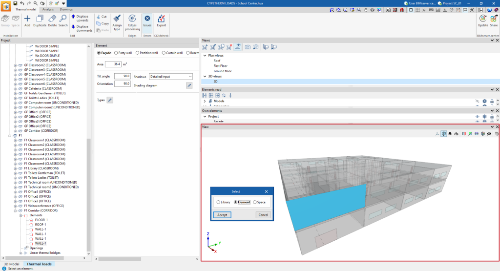
Selecting elements in the model view
The model view in the "‘Thermal model" tab at the bottom right shows and illuminates the selected tree elements. Furthermore, by clicking on the view itself, users can select the elements in the tree, the type they are assigned to in the library, or the space where they are located.
Defining shading diagrams
Shading diagrams define the shadows cast on external elements of the thermal model such as façades, curtain walls, overhangs and roofs, as well as external doors, windows and skylights.
These diagrams are generated automatically in the usual workflows, either by modelling the building and neighbouring buildings and other obstacles in the "3D Model" tab, or by linking the job to a BIMserver.center project and importing BIM models with the geometry of the building and neighbouring buildings and other obstacles.
However, these diagrams can be consulted and edited by selecting the corresponding elements in the project tree of the "Thermal model" tab and then selecting "Detailed definition" in the drop-down menu of the "Shading" section. In the window for editing the shading profiles, the program allows the following data to be modified:
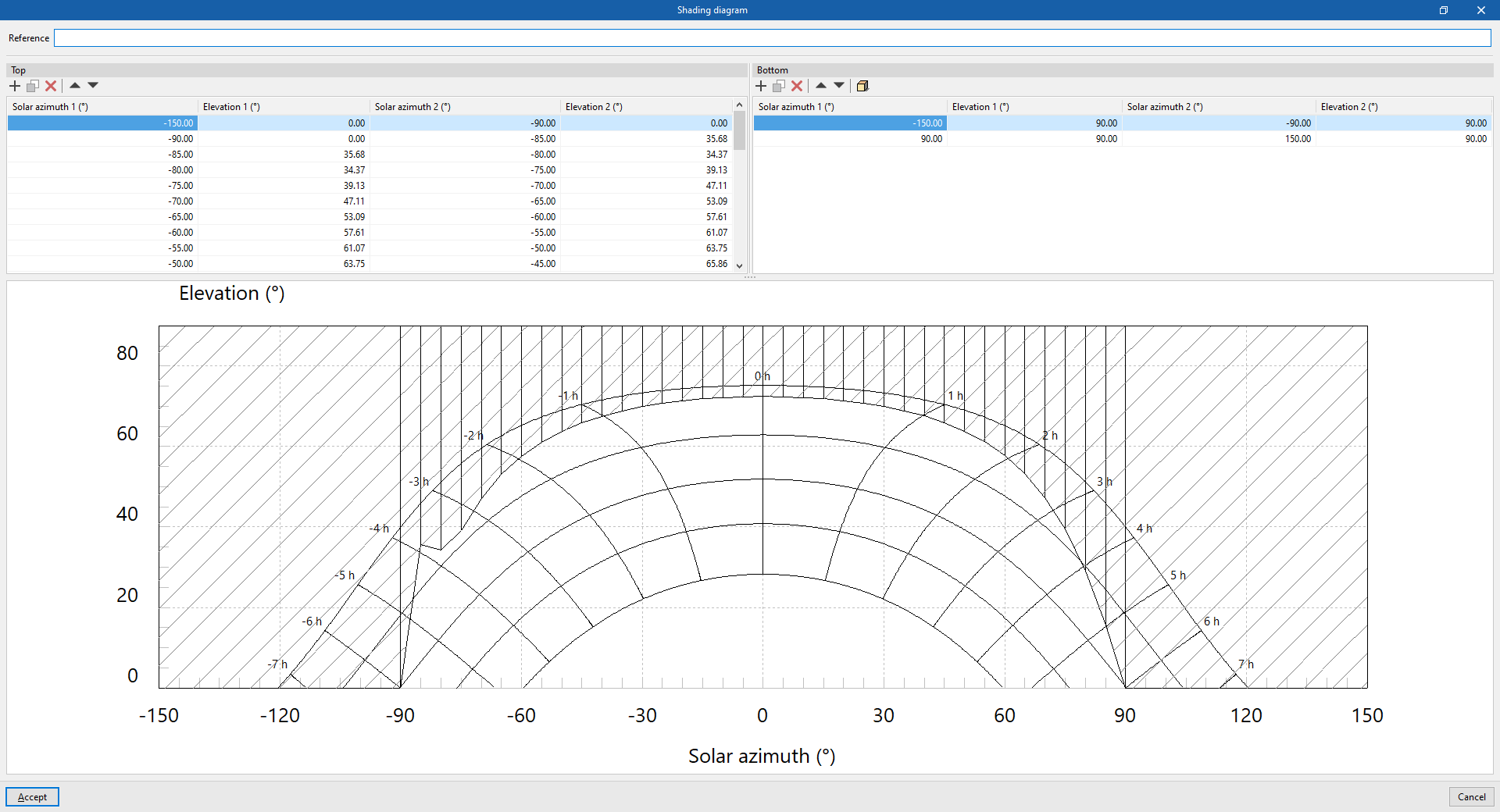
- Reference
Shading diagram reference.
Then, in the shadow diagram definition tables, users can consult the generated shadow polygons, enter them manually from their coordinates or generate them using the simplified option:
- Top
Manages the shadow polygons aligned with the upper elevation (90º). Each shadow polygon is a quadrilateral defined by four points with the following coordinates: (Solar Azimuth 1, 90º), (Solar Azimuth 1, Elevation 1), (Solar Azimuth 2, Elevation 2) and (Solar Azimuth 2, 90º). These shadow polygons can be used to define the shadows cast by cantilevers above the element.- Solar azimuth 1 (º)
This value must be between -180º and 180º. - Elevation 1 (º)
This value must be between 0º and 90º. - Solar azimuth 2 (º)
This value must be between -180º and 180º. - Elevation 2 (º)
This value must be between 0º and 90º.
- Solar azimuth 1 (º)
- Bottom
Manages the shadow polygons aligned with the bottom elevation (0º) or horizon. Each shadow polygon is a quadrilateral defined by four points with the following coordinates: Solar Azimuth 1, 0º; Solar Azimuth 1, Elevation 1; Solar Azimuth 2, Elevation 2; and Solar Azimuth 2, 0º. These shadow polygons can be used to define shadows cast by buildings or obstacles in front of the element.- Solar azimuth 1 (º)
This value must be between -180º and 180º. - Elevation 1 (º)
This value must be between 0º and 90º. - Solar azimuth 2 (º)
This value must be between -180º and 180º. - Elevation 2 (º)
EThis value must be between 0º and 90º.
- Solar azimuth 1 (º)
Finally, at the bottom, a solar chart is shown, indicating the position of the sun in the sky throughout the year, described by its height or elevation (or angle to the horizon) and its azimuth (angle to the south). The dashed portion shows the arrangement of the defined shadow polygons.
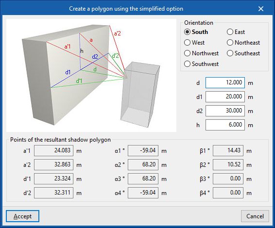
Create a polygon using the simplified option
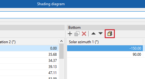
This option, available in the toolbar of the "Bottom" table, allows shadow polygons to be generated automatically by entering the following parameters, which indicate the geometry of the building or nearby obstacle and its position with respect to the element in a simplified form. Furthermore, a help scheme for the definition of these parameters is shown.
- Orientation (South / East / West / Northeast / Northwest / Southeast / Southwest / Southwest)
Orientation of the element where the shading diagram is being defined. - d
Distance from the element to the next building or obstacle. - d1
Length to the left of the next building or obstacle. - d2
Length to the right of the next building or obstacle. - h
Excess height of the building or nearby obstacle, with respect to the height of the centre of the element. - Points of the resulting shadow polygon (a'1, a'2, d'1, d'2, α1, α2, α3, α4, β1, β2, β3, β4)
These points and angles are automatically calculated when entering the other parameters in the wizard.
After accepting, the program generates the corresponding shadow polygons.
Processing edges in the thermal model
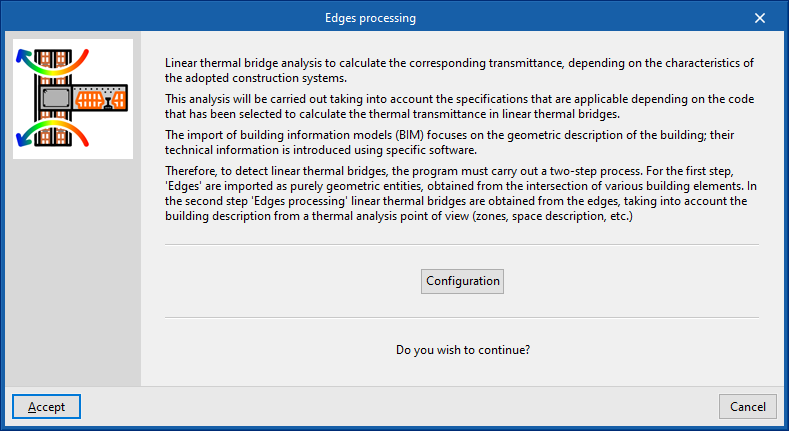
The analysis of linear thermal bridges is used to calculate the corresponding linear thermal transmittances according to the characteristics of the construction systems adopted. This analysis is carried out by considering the specifications applicable according to the code selected for calculating thermal transmittance in linear thermal bridges.
The import of building information models (BIM) focuses on the geometric description of the building. The technical information is entered into specific programs. Therefore, for the detection of linear thermal bridges, the program carries out two-step management:
- In the first stage, the edges of the building are imported as purely geometric entities, obtained from the intersection between different building elements. This is done when generating the thermal model, either from the "3D model" or in an import of BIM models in a job linked to BIMserver.center that contains files with this information.
- In the second stage, using edge processing, the linear thermal bridges are obtained from the edges and based on the description of the building from the point of view of thermal analysis (zoning, description of spaces, etc.). The program analyses the building and detects the geometric edges between a habitable room and the outside, and between a habitable room and a non-habitable room. Not all edges can give rise to linear thermal bridges.
This process is carried out by clicking on the "Edge processing" option in the "Edges" group in the top toolbar of the "Thermal model" tab, which in turn is located in the "Thermal loads" tab at the bottom.

By accepting the "Edge processing" window, the program modifies the data related to the "Linear thermal bridges" in the "Project" side tree of the "Thermal model" tab, both with respect to the "Libraries" and with respect to the linear thermal bridges assigned to each enclosure of the "Project" geometry. This generates the necessary types and adjusts the linear thermal transmittance value and the category associated with each of the linear thermal bridges.
Edge processing settings
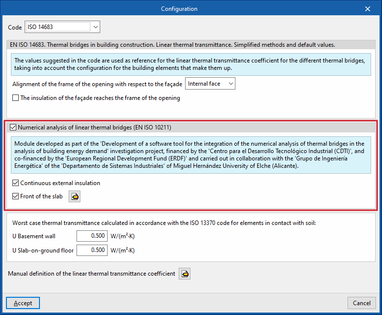
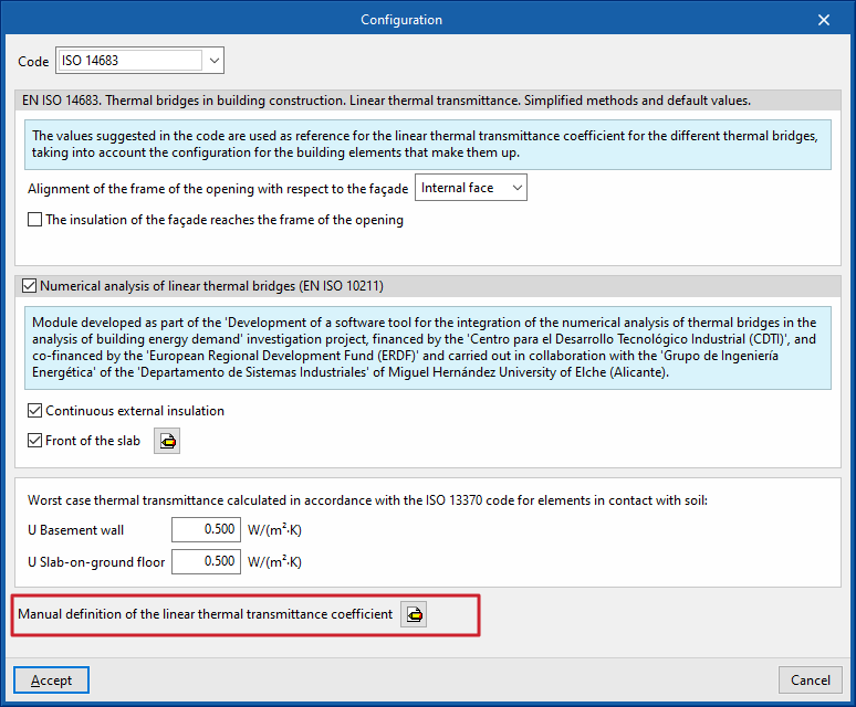
In the "Edges processing" window that appears when using this option, the "Configuration" option is used to adjust the following edge processing parameters:
- Code
- Alineación del marco del hueco respecto al cerramiento (EN ISO 10211) (optional)
- Manual definition of the linear thermal transmittance coefficient
The effects of the configuration of these parameter sets are detailed below.
Code selection
The "Code" drop-down menu allows users to select the reference standard for edge processing. Among the available codes are the following:
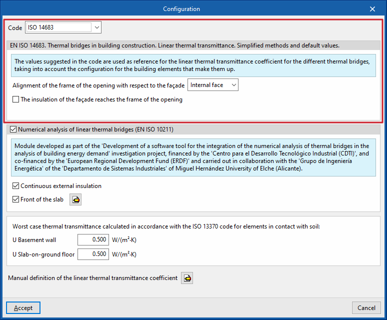
ISO 14683
Allows the following standard to be used as a reference: EN ISO 14683. Thermal bridges in building construction. Linear thermal transmittance. Simplified methods and default values.
The values proposed in this code for the linear thermal transmission coefficient of the different thermal bridges are used as a reference, considering the configuration of the building elements that comprise it.
The options available under this code are as follows:
- Alignment of the frame of the opening with respect to the façade (Interal face / External face)
- The insulation of the façade reaches the frame of the opening (optional)
ISO 14683 (Italy)
Allows the following standard to be used as a reference: EN ISO 14683. Thermal bridges in building construction. Linear thermal transmittance. Simplified methods and default values.
HE1 2006
Allows the following standard to be used as a reference: CTE DB HE1. Limitación de demanda energética (2006).
HE1 2013
Allows the following standard to be used as a reference: CTE DB HE1. Atlas de puentes térmicos DA DB-HE / 3.
Règles Th-Bât (France)
Allows the following standard to be used as a reference: Règles Th-Bât (Règles Th-U Fascicule 1 et 5).
REH
Allows the following standard to be used as a reference: SCE. Desempenho Energético dos Edifícios de Habitação (Cálculo de pontes térmicos lineares).
Numerical analysis of linear thermal bridges (EN ISO 10211)
The activation of this section allows the determination of the thermal transmittance in linear thermal bridges through the resolution and post-processing of a finite element heat transfer analysis model, based on EN ISO 10211.
This module is developed as part of the research project "Development of a software tool for the integration of the numerical analysis of thermal bridges in the calculation of the energy demand of buildings", financed by the Spanish centre for the development of industrial technology (CDTI), co-financed by the European Regional Development Fund (ERDF), and carried out in collaboration with the Energy Engineering Group of the Department of Industrial Systems of the Miguel Hernández University of Elche (Alicante).
The options available in this section are as follows:
- Continuous external insulation (optional)
- Front of the floor slab (optional)
Used to characterise the material layers of the front of the floor slab by entering their technical characteristics such as thickness, conductivity, thermal resistance, density or specific heat.
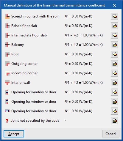
Manual definition of the linear heat transmission coefficient
The "Manual definition of the linear thermal transmission coefficient" window opens by clicking on the edit button available in this section, where the thermal bridge types associated with the selected standard are presented.
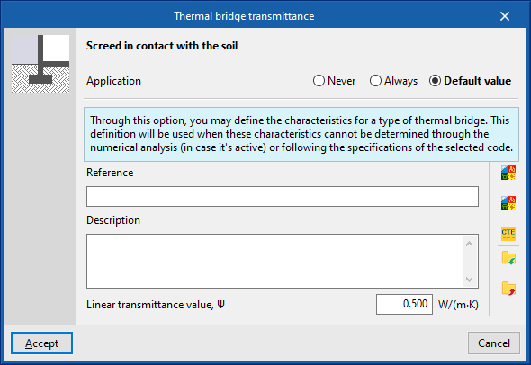
For each type of thermal bridge, by clicking on the edit button on the right-hand side, the following three options can be selected, which allow the definition of its linear thermal transmittance to be adjusted:
- Never
The thermal characteristics of the selected linear thermal bridge are not considered. - Always
Always considers the thermal characteristics that are defined for the selected linear thermal bridge. The program lets users enter a "Reference", a "Description" and the "Value of the linear thermal transmittance, ψ" for the type of bridge. - Default value
The thermal characteristics defined for the selected linear thermal bridge shall be used in the calculation when it has not been possible to determine them either by numerical analysis (if enabled) or following the specifications of the reference standard used. Similarly, the program lets users enter a "Reference", a "Description" and the "Linear transmittance value, ψ" for the bridge type, which will only be used in the case described.
Additionally, when selecting the "Always" or "Defaults" options, the program offers wizards on the right-hand side for automatically importing data from different code catalogues.
Order of priority for assigning the values of the thermal parameters
As a result, the program follows this order of priority for the assignment of thermal parameter values in edge processing:
- Value entered manually with the "Always" option or the "Never" option
These values can be defined for each type of thermal bridge in the "Configuration" window, by editing the "Manual definition of the linear thermal transmittance coefficient" section, editing a certain type of thermal bridge and finally selecting the option "Always" or "Never". - Value calculated by numerical analysis of linear thermal bridges
If the use of this module is activated in the "Configuration" window and for the types of thermal bridges it analyses. - Value obtained from the reference code
The reference standard is selected in the "Code" section of the "Configuration" window. - Value entered manually with the "Default value" option
These values can be defined for each type of thermal bridge in the "Configuration" window, by editing the "Manual definition of the linear thermal transmittance coefficient" section, editing a certain type of thermal bridge and finally selecting the "Default value" option.
Defining location data
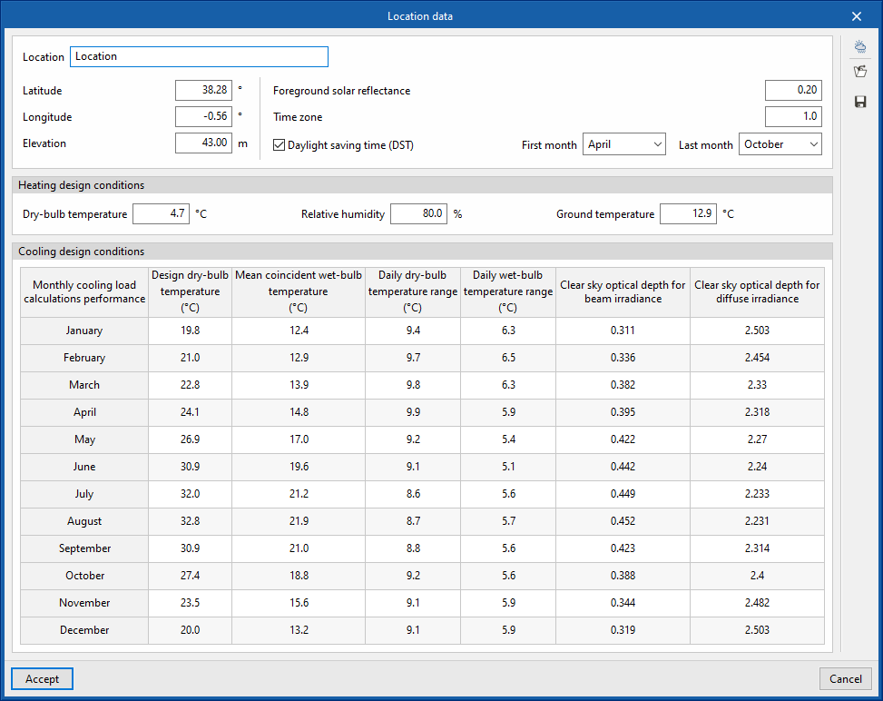
Defining the project location data is carried out with the "Location data" option in the "Project" group in the upper toolbar of the "Analysis" tab, which in turn is located in the "Thermal loads" tab at the bottom.

The data available for configuration is as follows:
- Location
- Latitude
- Longitude
- Elevation
- Foreground solar reflectance
- Time zone
- Daylight saving time (DST) (optional)
- First month
- Last month
- Heating design conditions
Sets the data required for the analysis of heating loads:- Dry-bulb temperature
- Relative humidity
- Ground temperature
- Cooling design conditions
Consults the data necessary for the analysis of cooling loads per month. By clicking on any cell in the table, the value of each magnitude for each month can be modified:- Design dry-bulb temperature
- Mean coincident wet-bulb temperature
- Daily dry-bulb temperature range
- Daily wet-bulb temperature range
- Clear sky optical depth for beam irradiance
- Clear sky optical depth for diffuse irradiance
Automatic data import
The "Import" option at the top right of the "Location data" window allows the automatic import of data from different climate databases. These include the following:
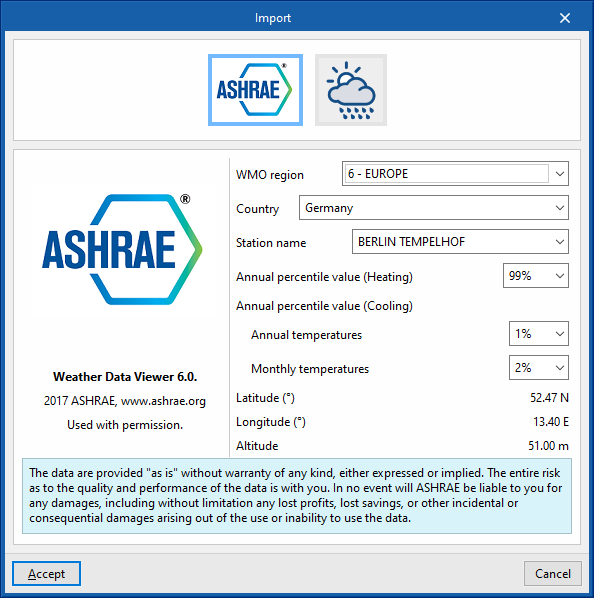
ASHRAE Weather Data Viewer 6.0
The climate data required for the analysis can be imported from ASHRAE's Weather Data Viewer 6.0 climate database, with 8118 stations located all over the world. Solar radiation data are calculated from ASHRAE's Clear-sky Solar Radiation model.
- WMO region
- Country
- Station name
- Annual percentile value (Heating) (99.6% / 99%)
- Annual percentile value (Cooling)
- Annual temperatures (0.4% / 1% / 2%)
- Monthly temperatures (0.4% / 2% / 5%)
- Latitude
- Longitude
- Altitude
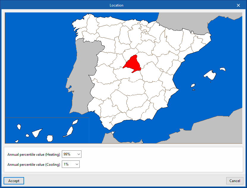
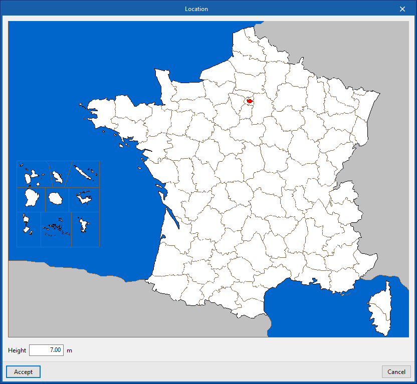
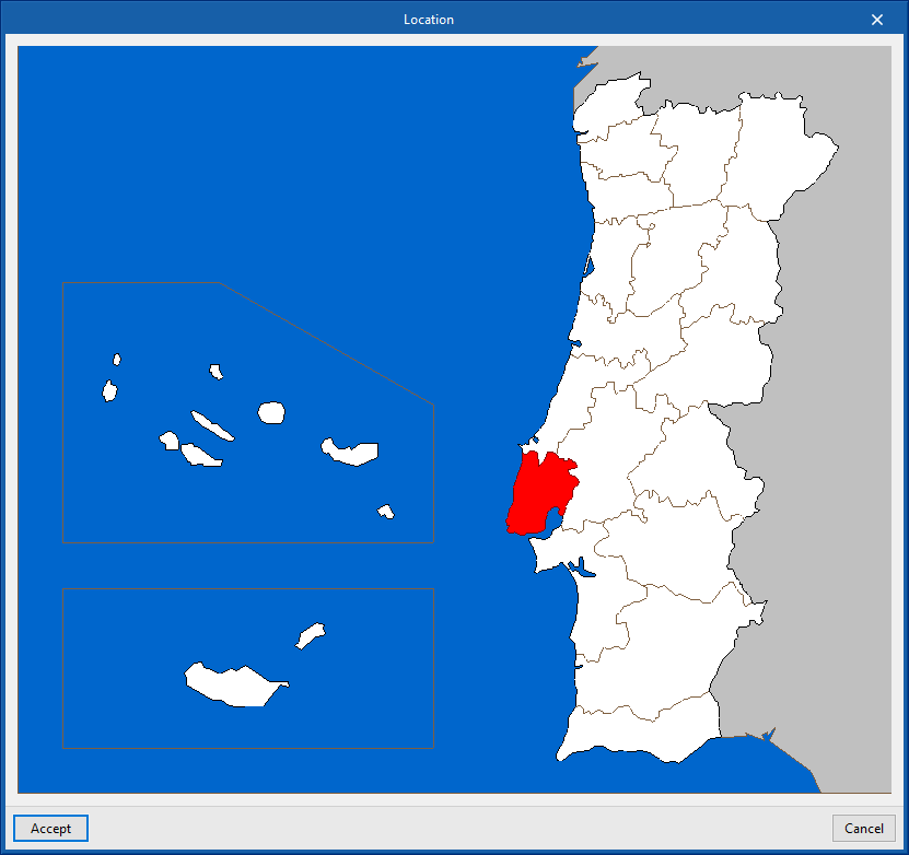
Importing data for Spain, France and Portugal
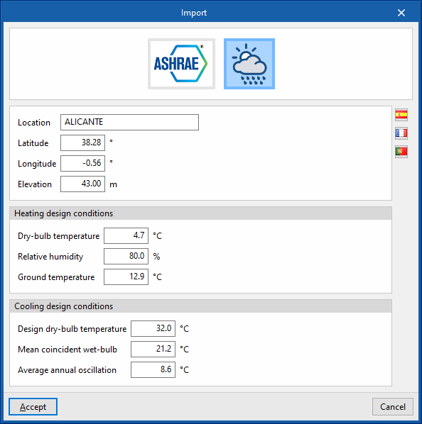
The origin of this data can be found in different reference standards for the countries mentioned. By clicking on the buttons with the flag symbols on the right-hand side, the exact location of the project in each of these countries can be defined. When accepted, the following data will be filled in:
- Location
- Latitude
- Longitude
- Altitude
- Heating design conditions
- Dry-bulb temperature
- Relative temperature
- Ground temperature
- Cooling design conditions
- Design dry-bulb temperature
- Mean coincident wet-bulb
- Average annual oscillation
Setting the calculation options
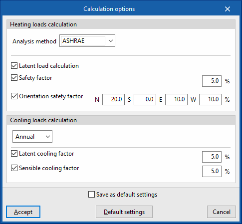
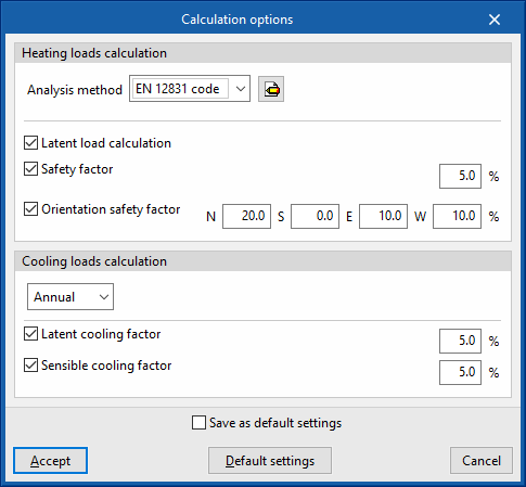
The "Calculation options" are available for configuration in the "Project" group in the upper toolbar of the "Analysis" tab, which in turn is located in the "Thermal loads" tab at the bottom.

The following options are available:
Calculation of heating thermal loads
- Analysis method
- ASHRAE
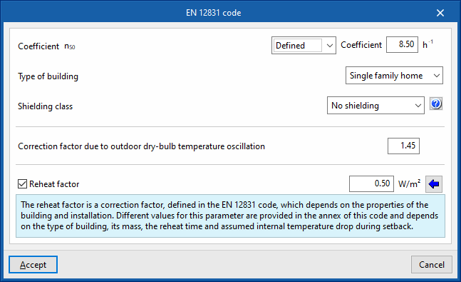
By checking this option, the program uses the ASHRAE Radiant Time Series Method (RTSM) to calculate heating loads. - EN 12831 code
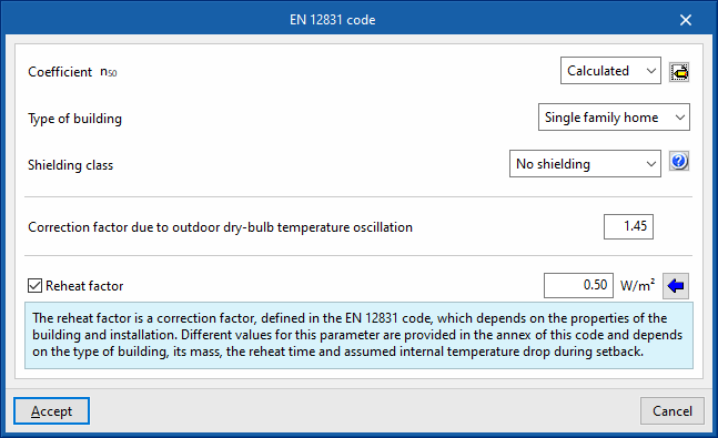
By checking this option, the calculation of heating loads is carried out according to EN 12831. In this case, the definition of the following parameters is required:- Coefficient n50
- Defined
- Analsyed
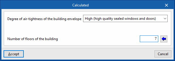
- Air tightness of the building envelope
- High (high-quality insulation of doors and windows)
- Medium (double-glazed windows, normal insulation)
- Low (single-glazed windows, no insulation)
- Air permeability of the envelope at 4 Pa
- Número de plantas del edificio
- Air tightness of the building envelope
- Type of building (Single family home / Household / Offices / Hotel / Restaurant / Teaching / Hospital / Other uses)
- Shielding class (No shielding / Moderate shielding / Heavy shielding)
- Correction factor due to outdoor dry-bulb temperature oscillation
- Reheat factor (optional)
The reheat factor is a correction factor, defined in EN12831, which depends on the characteristics of the building and the installation. In the appendices of this standard, different values are proposed for this parameter depending on the type of building, the mass of the building and the reheating time and the internal temperature drop assumed during disconnection. By clicking on the button on the right, these parameters can be defined and the associated value for the reheat factor can be imported:- Reheat time (hours)
- Interior temperature drop
- Building mass (High / Medium / Low)
- Coefficient n50
- ASHRAE
- Latent load calculation (optional)
- Safety factor (optional)
- Orientation safety factor (optional) (N, S, E, W)
Calculation of thermal cooling loads
- Anual / Monthly
- Latent cooling factor (optional)
- Sensible cooling factor (optional)
Defining hypotheses and zones
The definition of the zone scenarios and the zones considered in each scenario is required to be able to perform the thermal loads analysis. This is done using the tools in the "Installation" group in the upper toolbar of the "Analysis" tab, which is in turn located in the "Thermal loads" tab at the bottom.

The following options are available:
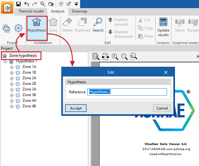
Hypothesis
This option is used to add a zone hypothesis to the project.
When adding a zone scenario, the following information is required:
- Reference
Zone scenario reference.
Each zone hypothesis of the building can be used to create a certain number of thermal zones of the building and to assign the desired spaces to each of the zones.
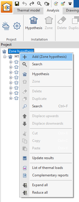
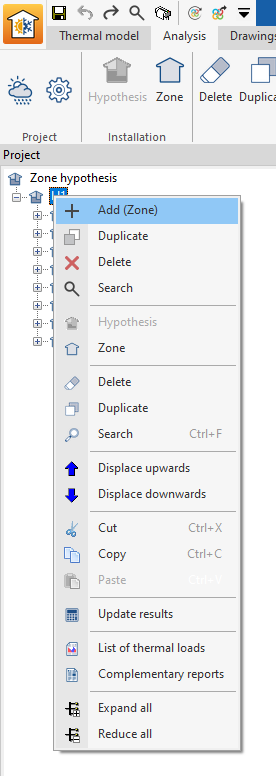
Hypotheses can also be added in the navigation tree of the "Calculation" tab by right-clicking on the base level and selecting "Add (Zone hypothesis)".
For example, in a two-storey office building, one hypothesis can be considered with two zones, one per floor, in case they have an independent use, and a second hypothesis with a single zone for the two floors, in case they have a joint use.
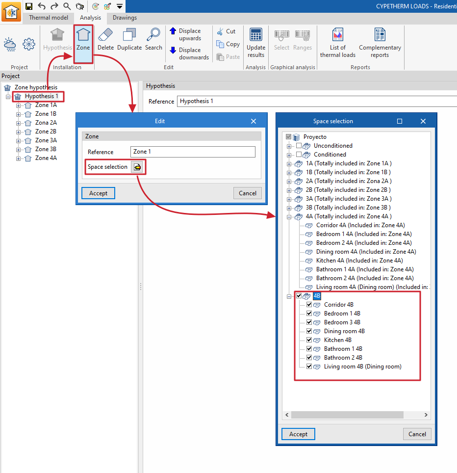
Zone
This option adds a zone within the selected zone scenario.
When entering a zone, the following data is required:
- Reference
Zone reference. - Space selection
In this section, the project spaces to be assigned to this zone must be selected. Only those spaces that have not been previously included in other zones of the same hypothesis can be selected.
Zones can also be added in the navigation tree of the "Analysis" tab by right-clicking on the level corresponding to a hypothesis and selecting "Add (Zone)".
For example, in a residential building, each dwelling may constitute a thermal zone. Together with the zones of the dwellings, another thermal zone including the common areas of the building would need to be added.
Analysing thermal loads and updating results
The analysis of thermal loads or the updating of calculation results after any modification of the model is done with the "Update results" tool in the "Calculation" group of the top toolbar, available in the tab with the same name, which in turn is located in the lower tab "Thermal loads".

To launch the thermal load analysis, the thermal model must be completed in the "Thermal model" tab and the zone hypothesis and zones as well as the location data and analysis options must be defined in the "Analysis" tab.
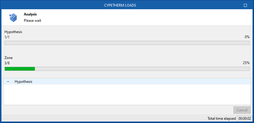
When using this tool, the program displays a window showing the analysis process, which will be carried out according to the selected methodology. When finished, it is possible to consult the calculation results by selecting the different elements in the project tree, located by default on the left-hand side.
Consulting information in the project tree under the "Analysis" tab
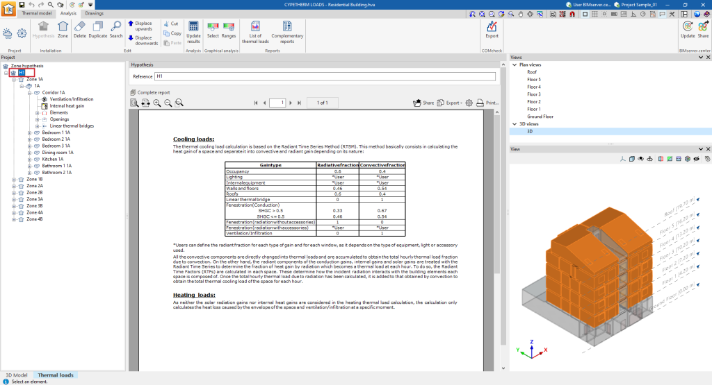
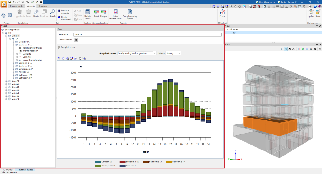
In the "Thermal loads" tab, on the left side of the "Analysis" tab, there is a tree of project elements. This tree is organised according to the different zone hypotheses defined, where the zones are included with the assigned spaces and, within each enclosure, the ventilation and infiltration data, the internal heat gains, and the calculated data for the associated elements, openings and linear thermal bridges.
This information is updated and can be consulted after the thermal load analysis of the building by using the "Update results" option in the top toolbar.
The information available at each level of this tree is as follows:
Information in the "Hypothesis" level
If a zone hypothesis is selected in the tree, the program displays an information text in the central part of the interface with details on the heat load analysis method used.
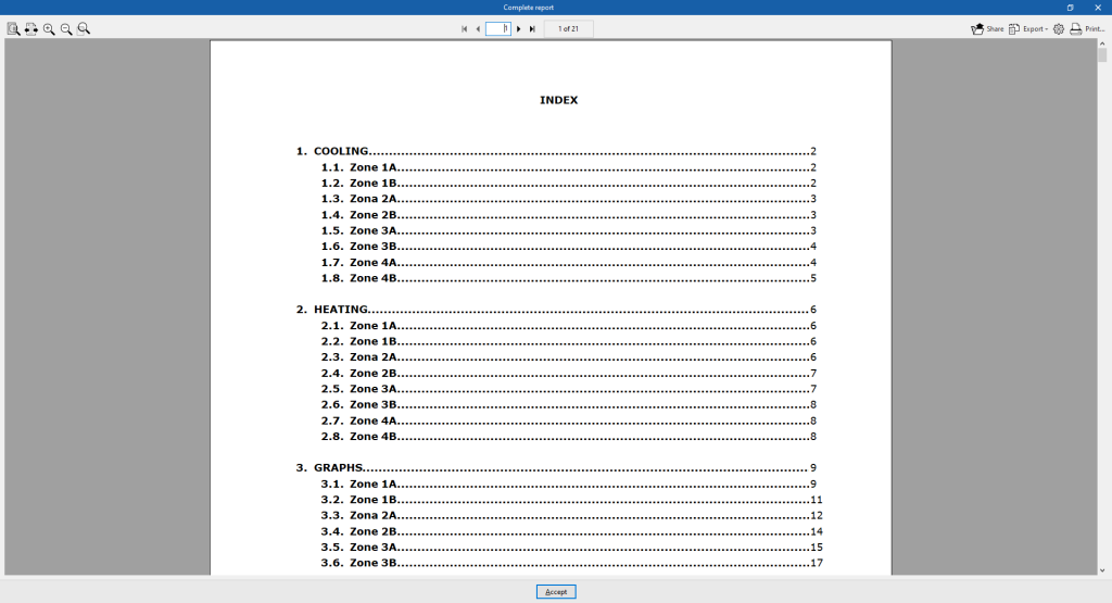
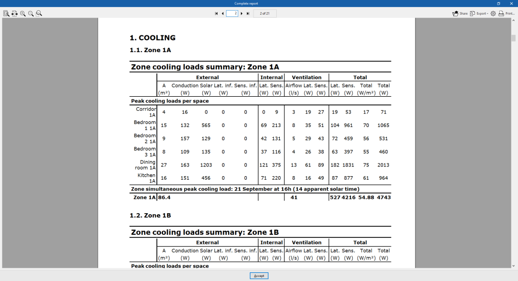
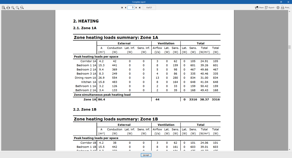
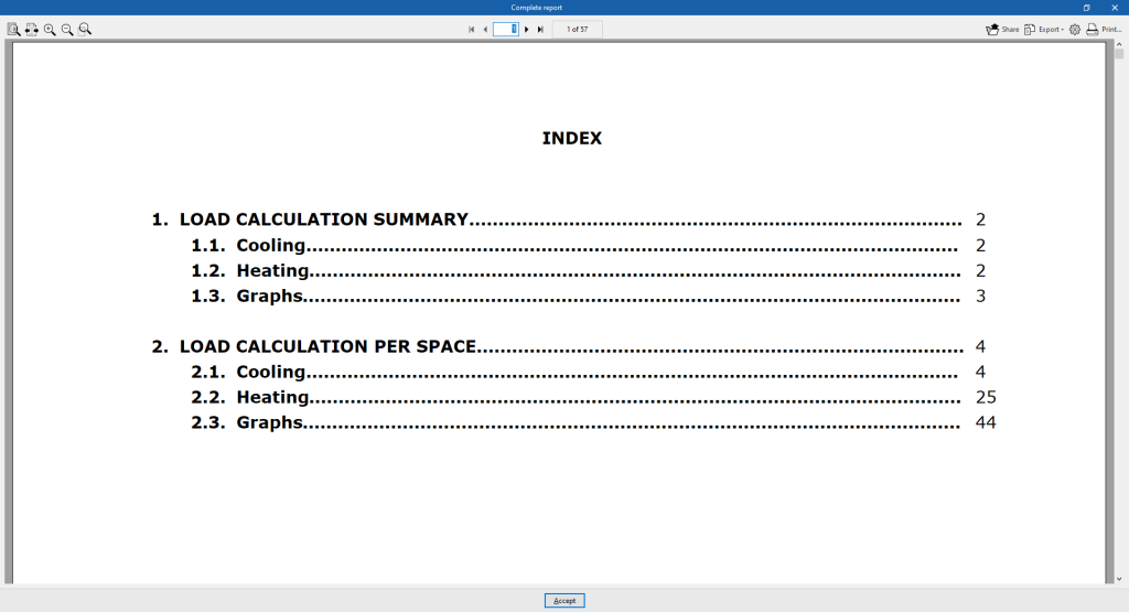
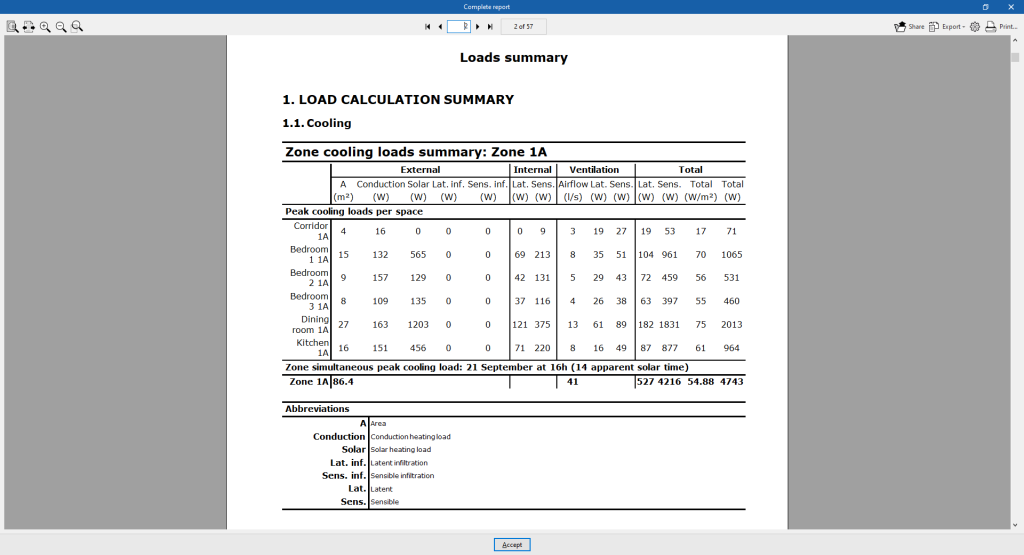
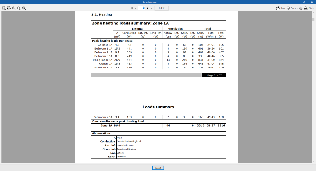
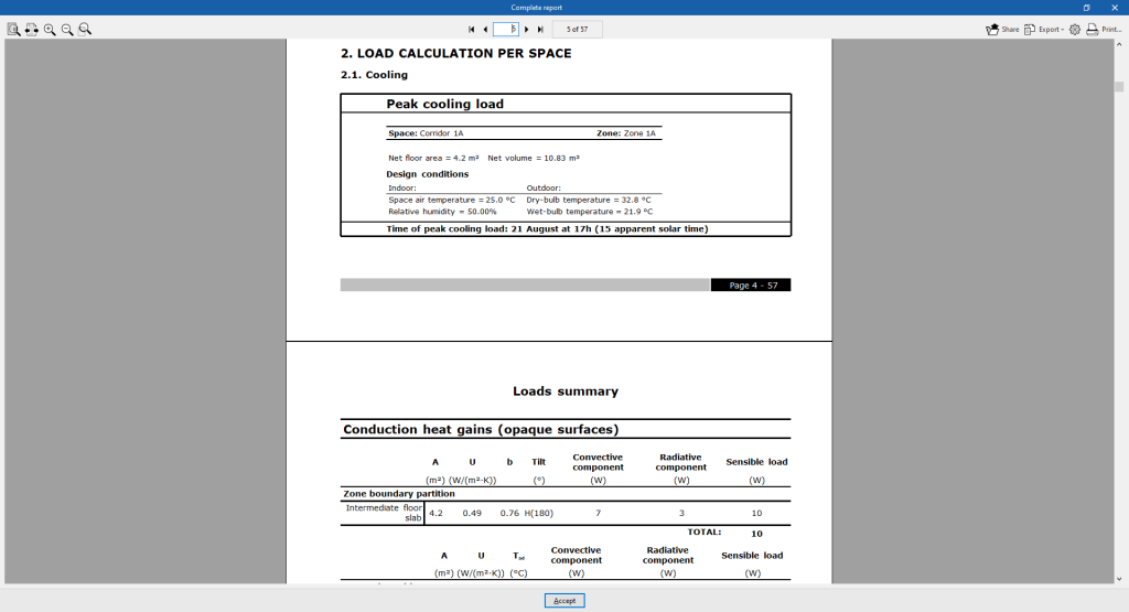
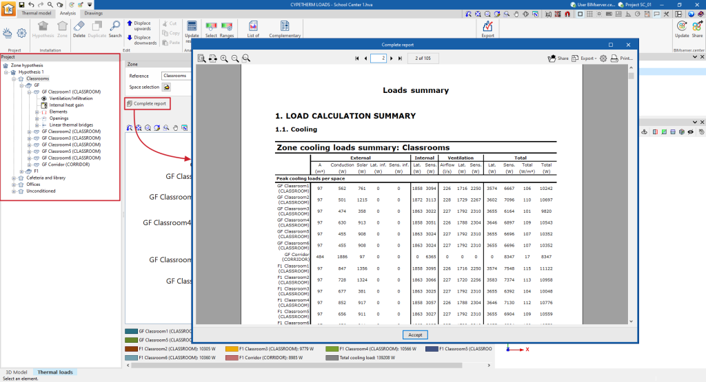
Furthermore, with the "Full report" option a "Thermal loads report" can be generated for all zones defined in the selected hypothesis, containing the following information:
- Cooling
- Zone cooling loads summary (External, Internal, Ventilation, Total)
- Peak cooling loads per space
- Zone simultaneous peak cooling load
- Zone cooling loads summary (External, Internal, Ventilation, Total)
- Heating
- Zone heating loads summary (External, Internal, Ventilation, Total)
- Peak heating loads per space
- Zone simultaneous peak heating load
- Zone heating loads summary (External, Internal, Ventilation, Total)
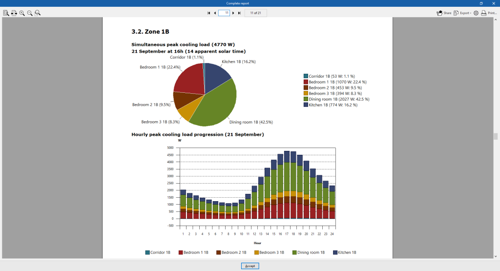
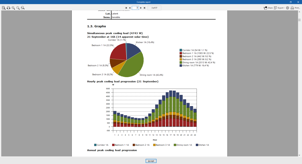
- Graphs
- Simultaneous peak cooling load
- Hourly peak cooling load progression
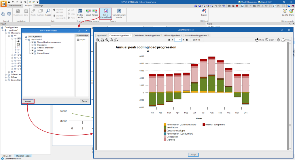
- Annual peak cooling load progression
- Peak heating load
Information in the "Zone" level
If a zone is selected in the tree, the program displays the drop-down menu "Results analysis", which allows the following information to be displayed in the central part of the program interface, depending on the selection made:
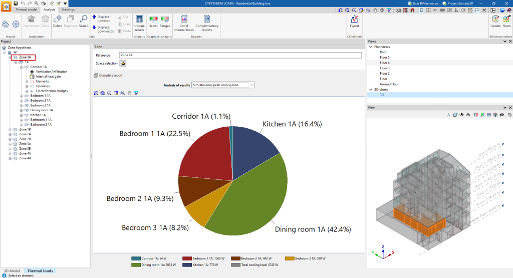
- Simultaneous peak cooling load
Shows a pie chart with the absolute values of cooling thermal loads and the percentage contribution of each space to the total cooling thermal load of the zone.
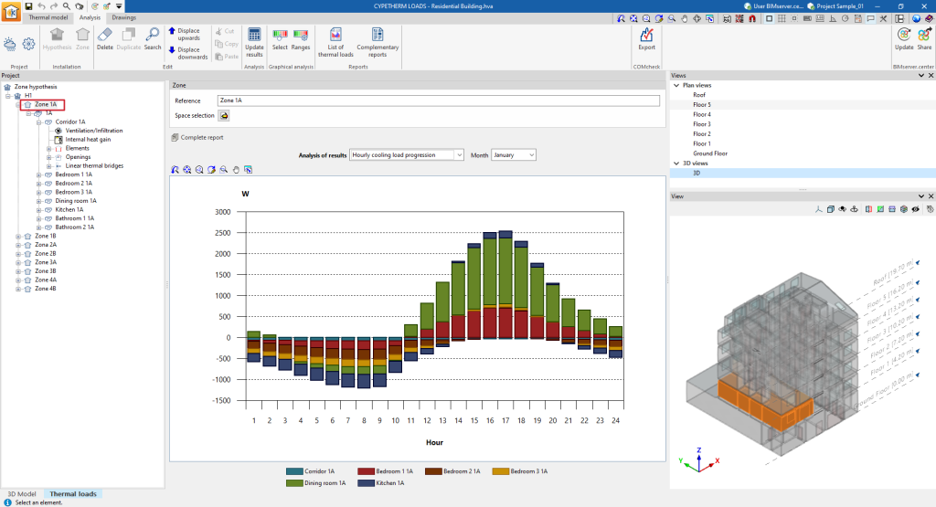
- Simultaneous peak cooling load (for each month)
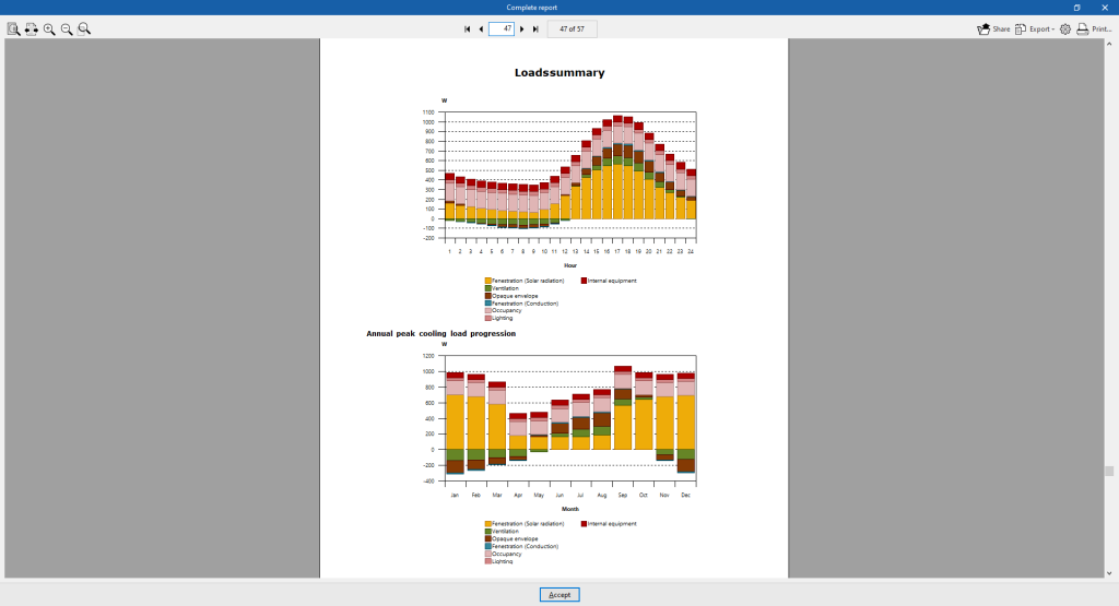
Displays a bar chart with the values broken down by space and aggregated by hour of the cooling thermal loads of the spaces in the area.
- Annual peak cooling load progression
Displays a bar chart with the values broken down by space and aggregated by month of the cooling thermal loads of the spaces in the area.
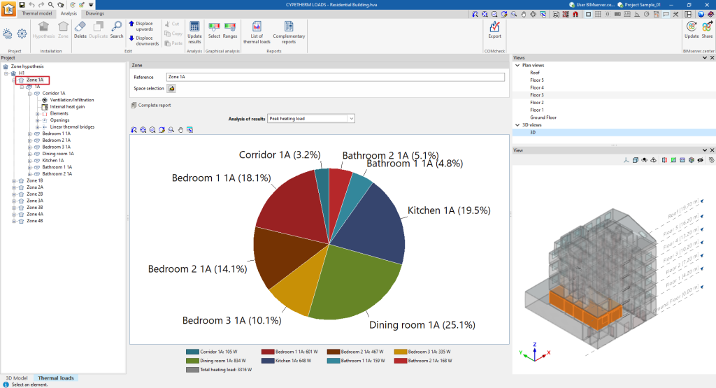
- Peak heating load
Displays a pie chart with the absolute values of heating loads and the percentage contribution of each space to the total heating load of the area.
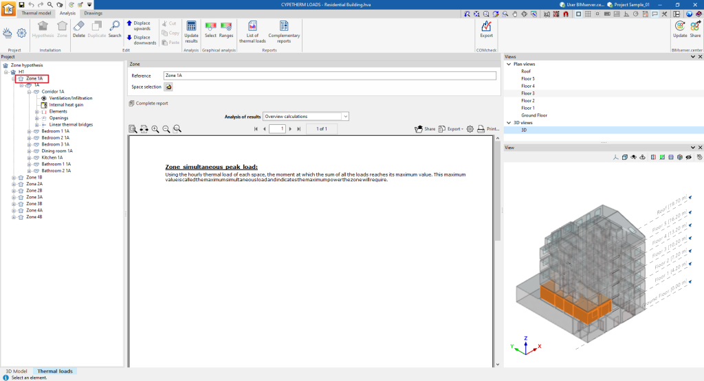
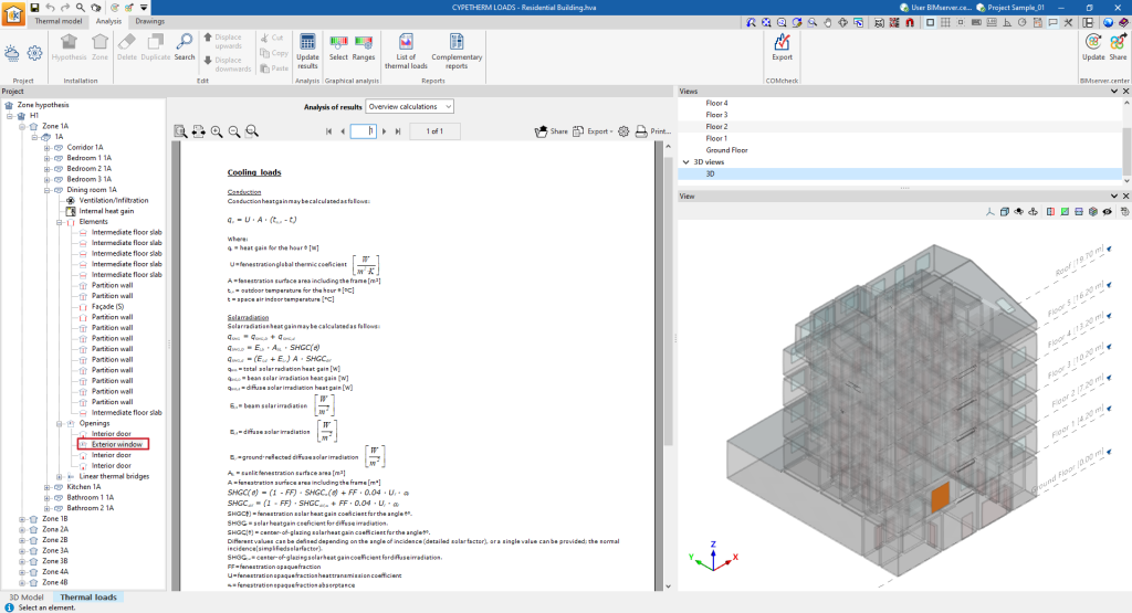
- Overview calculations
Displays an informative text with details on the analysis of the maximum simultaneous load of the zone.
In addition, with the "Complete report" option, a "Loads summary" can be generated, both for the selected zone and for all the spaces that comprise it, containing the following information:
- Load calculation summary (by zone)
- Cooling
- Zone cooling loads summary (External, Internal, Ventilation, Total)
- Peak cooling loads per space
- Zone simultaneous peak cooling load
- Zone cooling loads summary (External, Internal, Ventilation, Total)
- Heating
- Zone heating loads summary (External, Internal, Ventilation, Total)
- Peak cooling loads per space
- Zone simultaneous peak cooling load
- Zone heating loads summary (External, Internal, Ventilation, Total)
- Graphs
- Simultaneous peak heating load
- Hourly peak cooling load progression
- Annual peak cooling load progression
- Peak heating load
- Cooling
- Summary of load analysis results for each space
- Cooling
- Peak cooling load
- Conduction heat gains (opaque surfaces)
- Conduction heat gains (fenestration)
- Internal heat gains
- Ventilation and infiltration heat gains
- Total cooling load
- Peak cooling load
- Heating
- Peak heating load
- Conduction heat losses
- Ventilation and infiltration heat losses
- Total heating load
- Peak heating load
- Graphs
- Peak cooling load
- Peak heating load
- Hourly cooling load progression
- Annual peak cooling load progression
- Maximum heating load
- Cooling
Information in the "Space" level
If a space is selected in the tree, the program displays the "Results analysis" drop-down menu, which allows the following information to be displayed in the central part of the program interface, depending on the selection made:
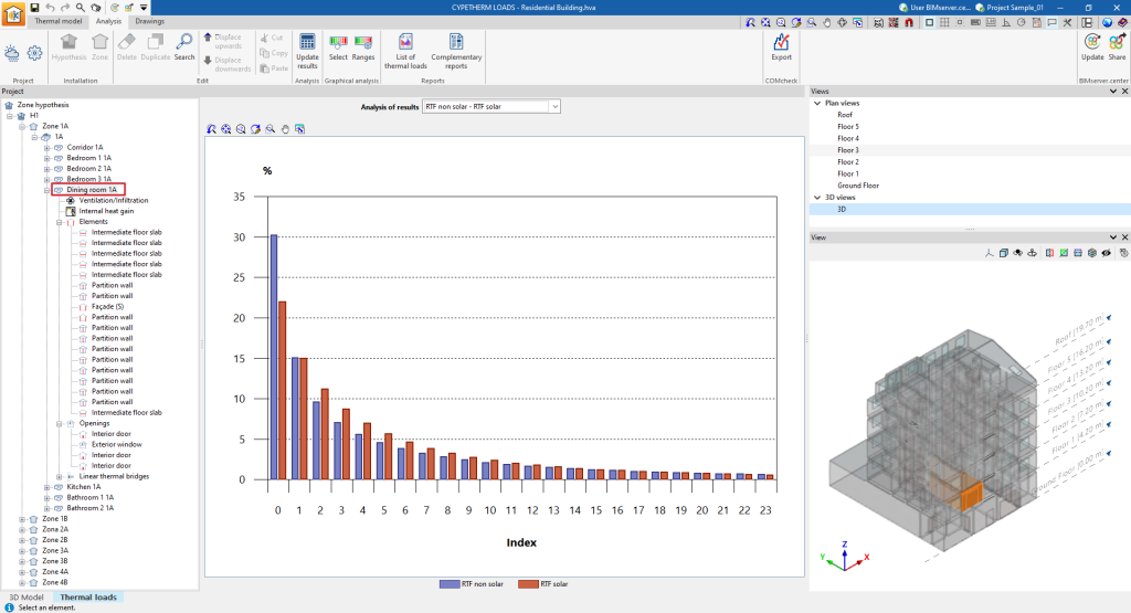
- RTF non solar - RTF solar
Displays a bar chart with the values (%) of the RTF indices obtained in the calculation.
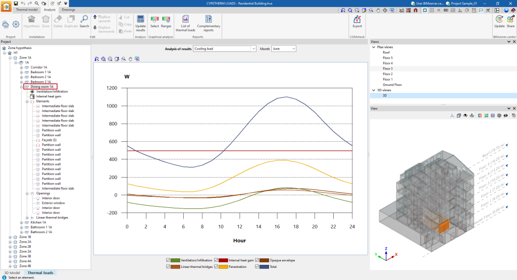
- Cooling load (for each month)
Displays a line graph with broken-down values of the cooling thermal loads of the space for each month.
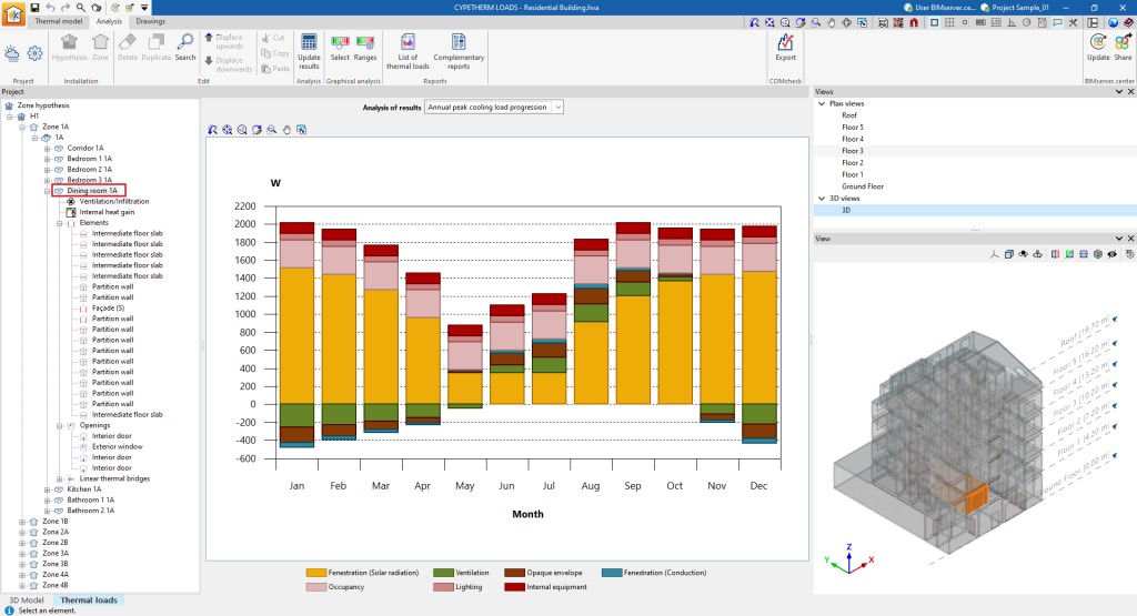
- Annual peak cooling load progression
Displays a bar chart with broken-down values of the cooling thermal loads of the space and aggregates by month.
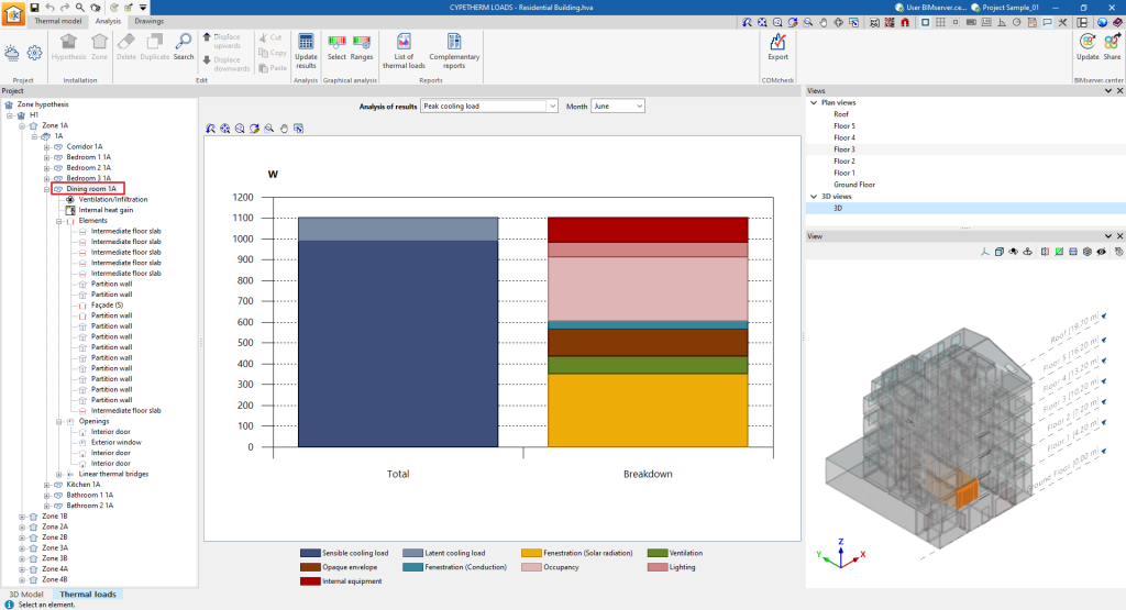
- Peak cooling loads
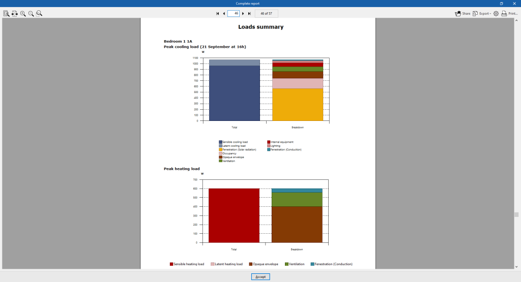
Displays a bar chart with the total value and the aggregate of the disaggregated values of the space cooling loads for each month.
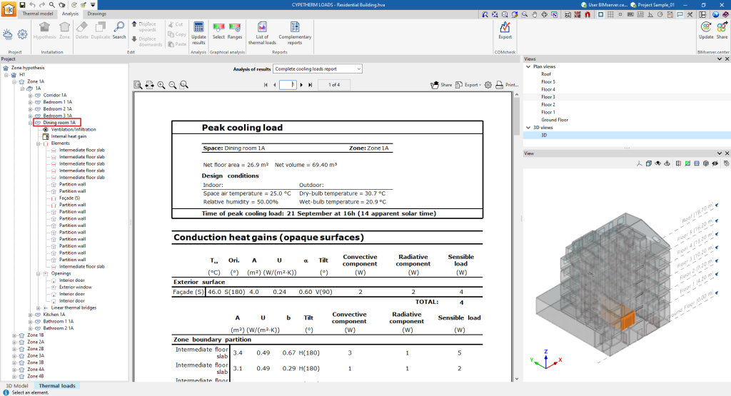
- Complete cooling loads report
Displays the cooling thermal loads report for the enclosure, which includes the following data:- Peak cooling loads
- Conduction heat gains (opaque surfaces)
- Conduction heat gains (fenestration)
- Internal heat gains
- Ventilation and infiltration heat gains
- Total cooling load
- Peak cooling loads
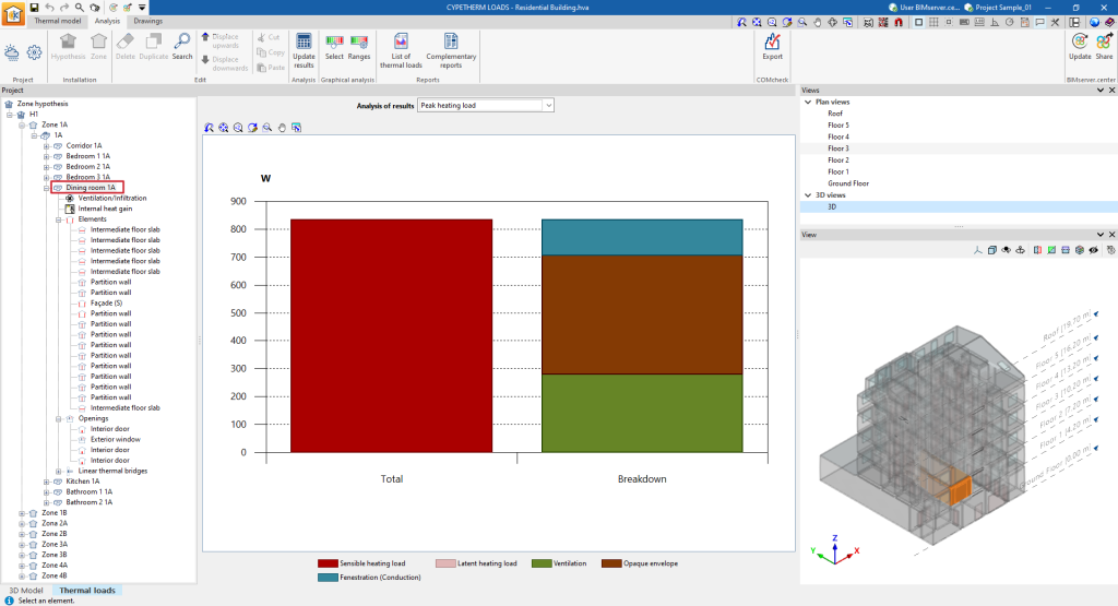
- Peak heating load
Displays a bar chart with the total value and with the aggregate of the disaggregated values of the heating loads of the space.
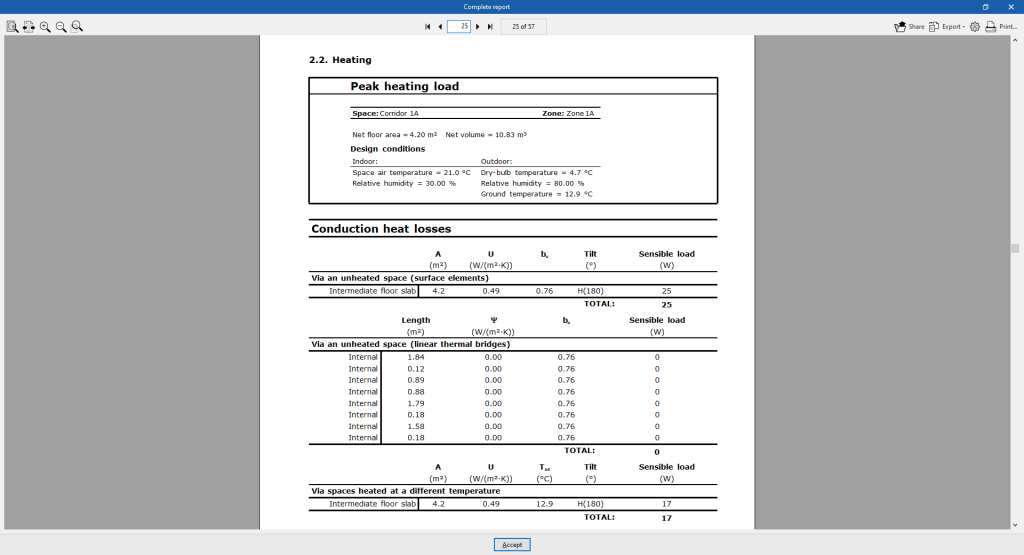
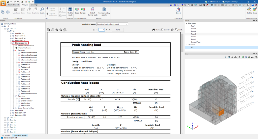
- Complete heating loads report
Displays the heating loads report for the space, which includes the following data:- Peak heating load
- Conduction heat losses
- Ventilation and infiltration heat losses
- Total heating load
- Peak heating load
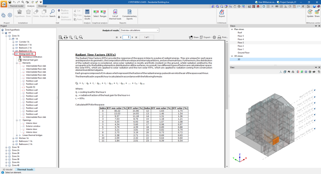
- Overview calculations
Displays an informative text with details on the calculation of the radiant time factors (RTF) in the space.
Information related to the ventilation/infiltration of the space
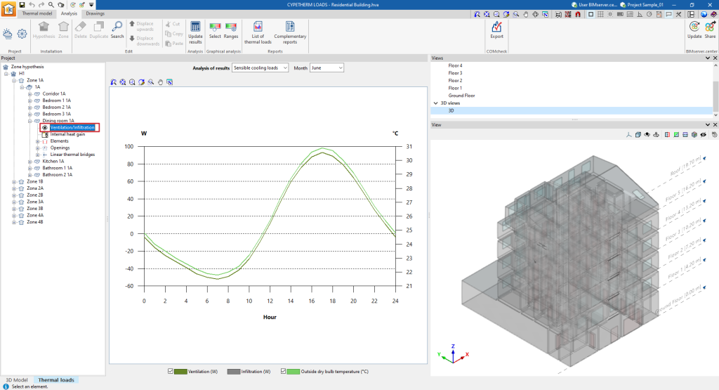
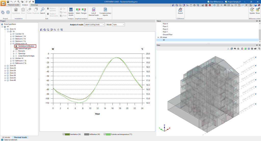
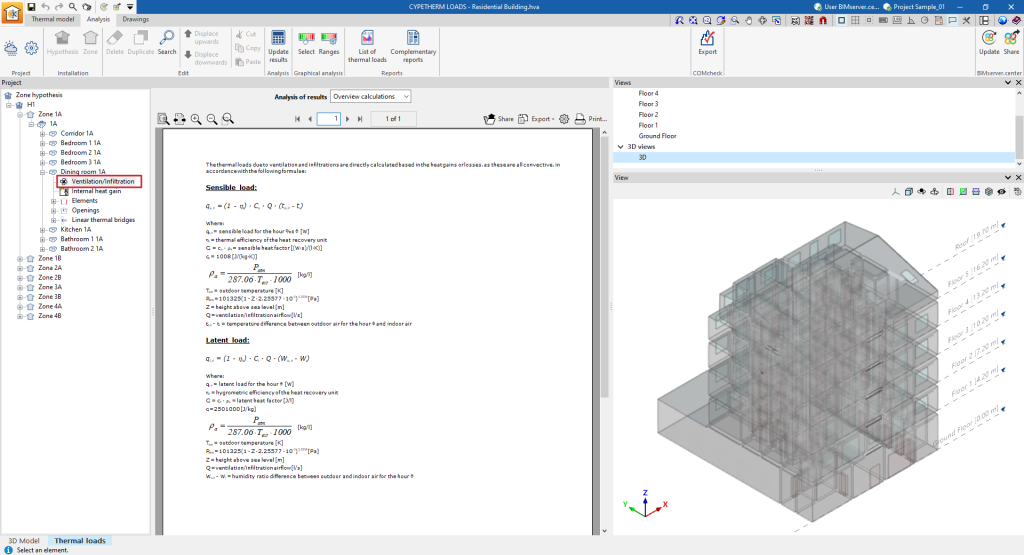
If a space is selected in the tree and then the "Ventilation/Infiltration" level is selected, the program displays the "Analysis of results" drop-down menu, which allows the following information to be displayed in the central part of the program interface, depending on the selection made:
- Sensible cooling loads
Displays the hourly evolution of the sensible cooling loads due to ventilation and infiltration and the dry outdoor temperature for the selected month.
- Latent cooling loads
Displays the hourly evolution of the latent cooling loads due to ventilation and infiltration, and the outdoor humid temperature for the selected month.
- Overview calculations
Displays an informative text with details on the calculation of sensible and latent loads due to ventilation and infiltration.
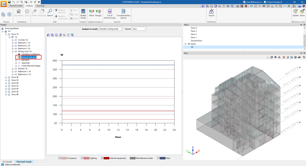
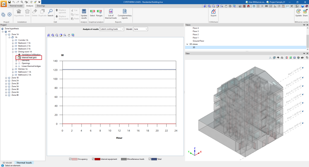
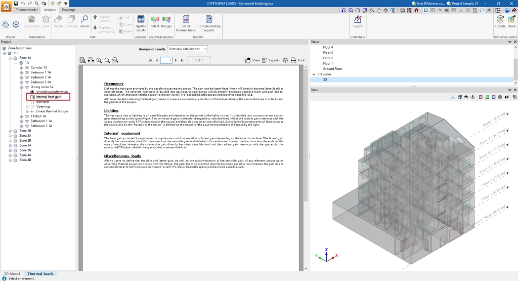
Information on the internal heat gain of the space
If a space is selected in the tree and then the "Internal heat gain" level is selected, the program displays the drop-down menu "Analysis results", which allows the following information to be displayed in the central part of the program interface, depending on the selection made:
- Sensible cooling loads
Shows the hourly evolution of the sensitive cooling loads due to occupancy, lighting, internal equipment and other loads, and the total sensitive loads, for the selected month.
- Latent cooling loads
Shows the hourly evolution of latent cooling loads due to occupancy, lighting, internal equipment and other loads, and total sensible loads, for the selected month.
- Overview calculations
Displays an informative text with details on the calculation of internal heat gains.
Information on elements in the space
If a space is selected in the tree and then the "Elements" level is selected, the program displays an information text with details on the analysis of the cooling and heating loads in the building elements.
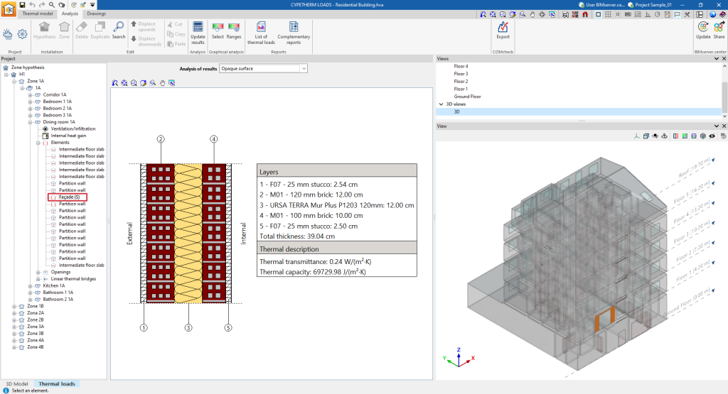
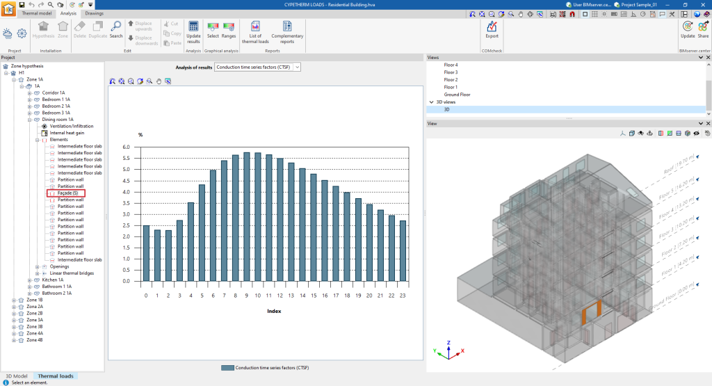
If, after having displayed the "Elements" level, a particular element is selected in the tree, the program displays the "Results analysis" drop-down menu, which allows the following information to be displayed in the central part of the program interface, depending on the selection made:
- Opaque element
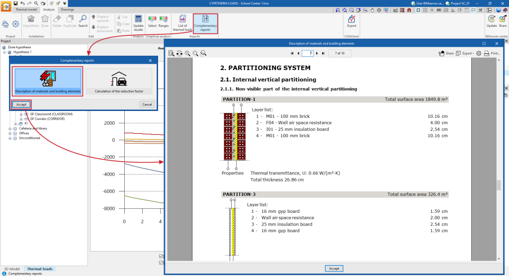
Displays the construction detail of the selected building element with the layers of materials that compose it, its total thickness, and the parameters that describe its thermal characterisation, such as thermal transmittance and thermal capacity.
- Conduction time series factors (CTSF)
Displays a bar chart with the values (%) of the driving time series factors (CTSF) obtained in the analysis.
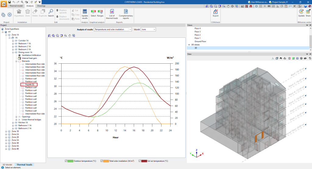
- Temperatures and solar irradiation
Shows the hourly evolution of the outdoor temperature, the sun-air temperature and the total solar irradiation for the selected month.
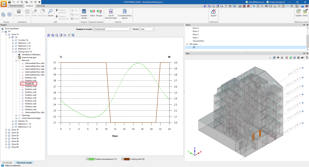
- Cooling load
Shows the hourly evolution of the cooling load as well as the outdoor temperature for the selected month.
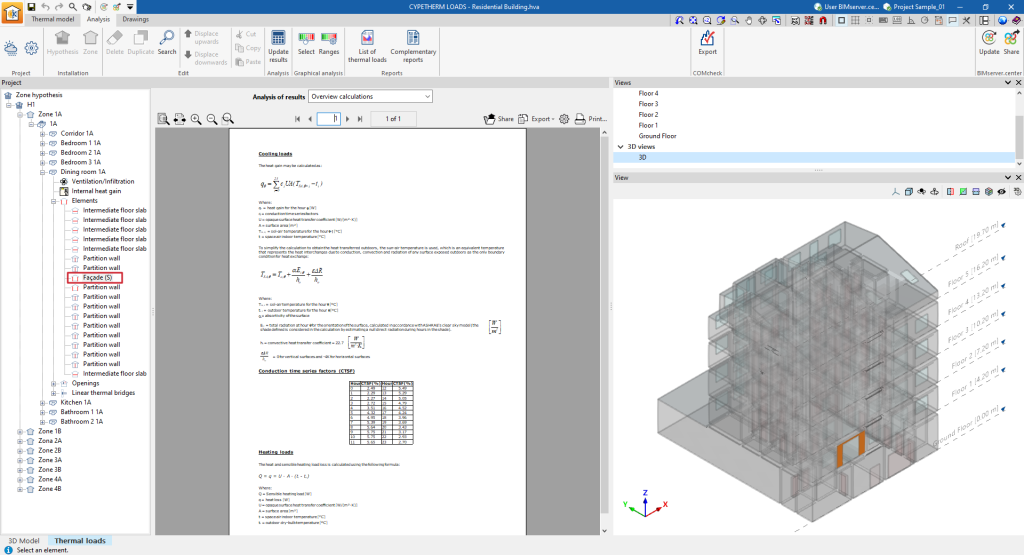
- Overview calculations
Displays an informative text with details on the analysis of the cooling loads, including the analysis of the sun-air temperature, the driving time series factors (CTSF), and the heating loads across the element.
Information in the openings of the space
If a space is selected in the tree and then the "Openings" level is selected, the program displays an information text with details on the analysis of the cooling and heating loads in the openings.
If, after displaying the "Openings" level, a particular gap is selected in the tree, the program displays the "Results analysis" drop-down menu, which allows the following information to be displayed in the central part of the program interface, depending on the selection made:
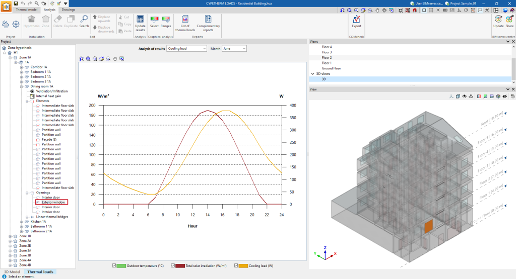
- Cooling load
Shows the hourly development of the cooling load, total solar irradiation and outdoor temperature for the selected month. - Overview calculations
Displays an informative text with details on the analysis of the cooling loads, including the analysis of the heat gains from conduction and solar radiation, and of the heating loads through the shaft.
Information on linear thermal bridges in the space
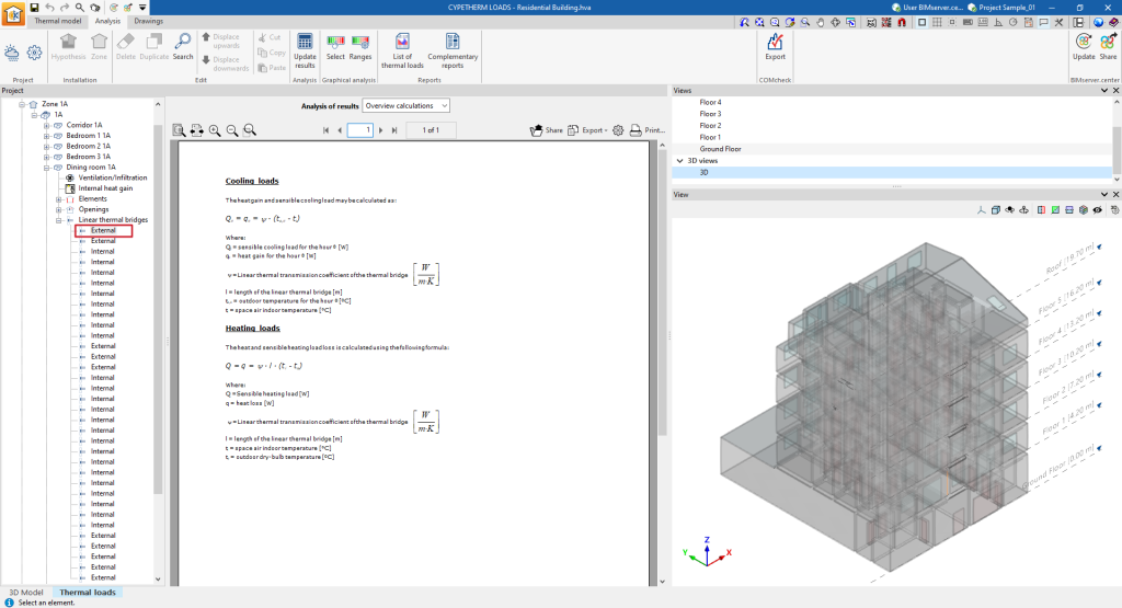
If a space is selected in the tree and then the "Linear thermal bridges" level is selected, the program displays an information text with details on the intervention of linear thermal bridges in the load calculation.
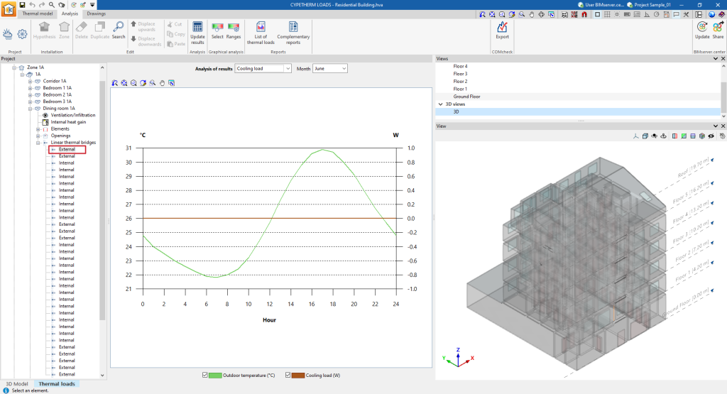
If, after displaying the "Linear thermal bridges" level, a specific linear thermal bridge is selected in the tree, the program displays the "Results analysis" drop-down menu, which allows the following information to be displayed in the central part of the program interface, depending on the selection made:
Tools in the "Drawings" tab
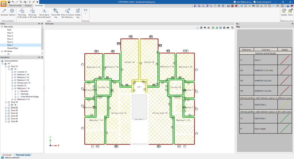
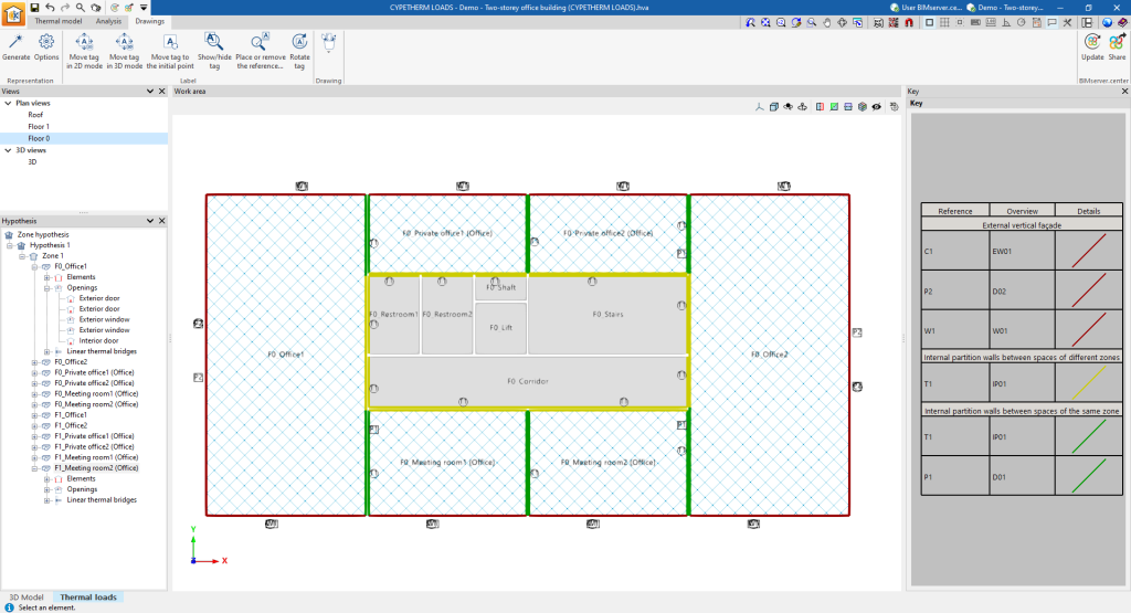
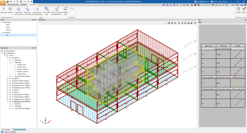
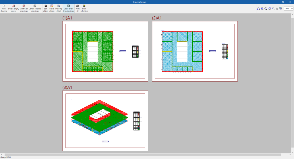
The "Drawings" tab, within the ‘’Thermal loads‘’ tab, is used to create and edit the drawings of the thermal envelope used for each of the zone hypotheses calculated in the project.
This tab has an interface with the following areas:
Views
In this area, located by default at the top of the left-hand side, users can select the view to be represented in the work area (plan views, 3D views, elevations, etc.). Views can be created and edited in the section of the same name in the "Thermal model" tab.
Hypothesis
This area, located at the bottom of the left-hand side, offers a navigation tree where users can select the zone hypotheses, the zones, the spaces or the elements, the openings and the linear thermal bridges they are composed of. In the work area, the program highlights the elements of the model associated with the level selected in the tree in orange.
Work area
The work area, in the centre of the interface, is a 3D environment where the representation of the model is displayed according to the selected view. The elements of the envelope are coloured according to the indicated key.
Key
In this area, located on the right, the drawing key is displayed, which indicates the "Details" of the graphic representation used for each element, its "Reference" and its "Description".
LThe following features are available in the top options bar:
"Representation" group

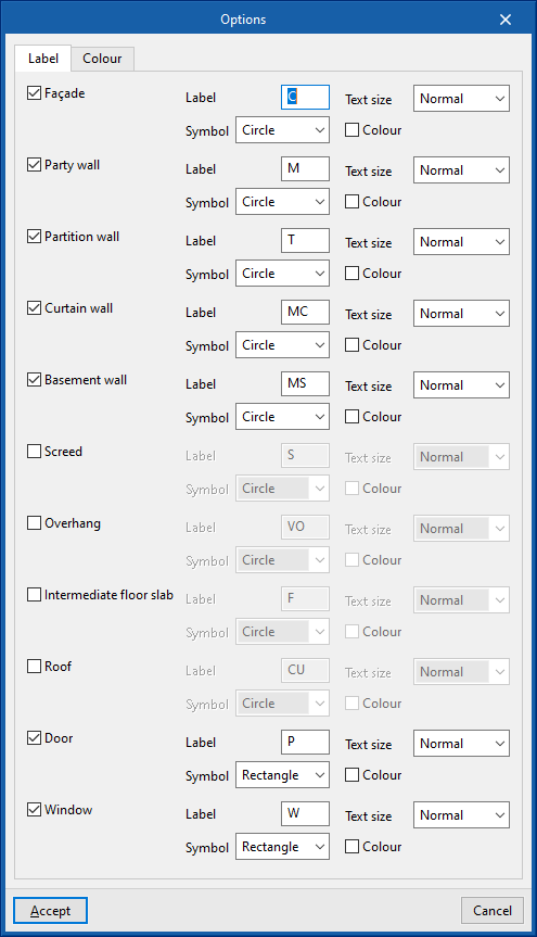
- Options
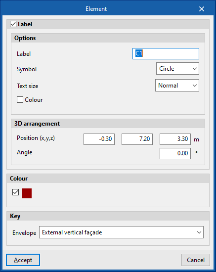
Manages the tag and colour of the model elements in the drawings.- "Label" group
Modifies the label text, its symbol, text size and colour for each of the elements in the model:- Façade
- Party wall
- Partition wall
- Curtain wall
- Basement wall
- Screed
- Overhang
- Intermediate floor slab
- Roof
- Door
- Window
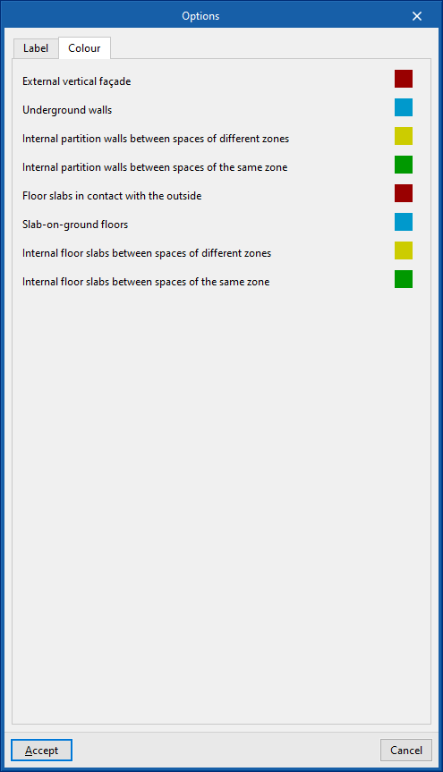
- "Colour" group
Modifies the representation colour of the elements of the model according to their category:- External vertical façade
- Underground walls
- Internal partition walls between spaces of different zones
- Internal partition walls between spaces of the same zone
- Floor slabs in contact with the outside
- Slab-on-ground floors
- Internal floor slabs between spaces of different zones
- Internal floor slabs between spaces of the same zone
- "Label" group
If necessary, after generating the drawings, clicking on each element in the work area opens an editing window where its properties and those of its label can be modified.
"Label" group

The options in this group allow the following editing operations to be carried out on the labels generated for the elements of the model:
| Move tag in 2D mode | Moves the selected tag on the element's floor plan. | |
| Move tag in 3D mode | Moves the selected tag in the 3D space. | |
| Move tag to the initial point | Returns the tag of the selected element to the initial point. | |
| Show/hide tag | Shows or hides the selected element's tag. | |
| Place or remove the reference line of the tag | Shows or hides the line linking the tag to the selected element it refers to. | |
| Rotate tag | Rotate the tag over its position. |
"Drawing" group

The options in this group are used to enter the following drawing resources:
| Elevation | Enters an elevation between two selected points, indicating the line colour, line thickness, and text size. | |
| Line | Inserts a line between two selected points, indicating its colour and thickness. | |
| Text | Enters a text and a reference line, indicating its colour, the line thickness and the text size. | |
| Text box | Enter a left-aligned, right-aligned or centred text box, indicating the colour and size of the text, the properties of the frame and the background fill. | |
| Arc | Enter an arc and, optionally, its radius, indicating the line colour, line thickness and text size. | |
| Circle | Enter a circle and, optionally, its radius or diameter, indicating the line colour, line thickness, and text size. | |
| Rectangle | Enter a rectangle and, optionally, its area, indicating the line colour, line thickness and text size. | |
| Area | Enter a dotted polygon and, optionally, its area, indicating the line colour, line thickness, and text size. | |
| Polyline | Inserts a polyline by points, indicating its colour and thickness. | |
| Edit | Edit the properties of the selected drawing resource. | |
| Delete | Deletes the selected drawing resources. | |
| Move | Moves the selected drawing resource or parts of it. | |
| Assign | Assigns the properties of a drawing resource to others. When selecting a drawing resource, resources with the same properties are highlighted in orange. |
Results output
Consulting the results in the "Analysis" tab
After the calculation, the program can display the results on screen in the project tree of the "Analysis" tab, including the cooling and/or heating thermal loads of the zones, the spaces and each of the associated building elements, as well as various information such as graphs and descriptive texts of the analysis methodology used.
Graphical analysis of results
Using the options in the "Graphical analysis of results" group in the main toolbar of the "Analysis" tab, under the "Heat loads" tab, the analysed heat load values can be displayed in the "View" in the lower right-hand area by default. The zones or spaces are coloured and a colour scale is displayed as a key.
Select
Using the "Select" option, users can select whether the graphical analysis is carried out per zone or space, and which magnitude is used in the coloured representation of the values:
- Graphical analysis (optional)
- Zone
- Simultaneous peak cooling load / Peak heating load
- Hypothesis
Selection of the zone hypothesis to be represented.
- Space
- Peak cooling loads per space / Peak heating loads per space
- Zone
Ranges
By default, the program shows the minimum and maximum values of each magnitude obtained in the analysis for the whole building. However, the colour scale can be adjusted in the dialogue box that appears when clicking on the "Ranges" option, which allows indicating specific ranges of minimum and maximum values defined for each magnitude:
- Simultaneous peak cooling load (optional) (Minimum, Maximum)
- Peak heating load (optional) (Minimum, Maximum)
- Peak cooling loads per space (optional) (Minimum, Maximum)
- Peak heating loads per space (optional) (Minimum, Maximum)
Reports by hypothesis and zone
The program generates reports with results for the zone hypotheses and zones, including the data calculated in all the spaces included in each of them. To do this, select the corresponding level in the project tree of the "Analysis" tab, either "Hypothesis" or "Zone", and click on the "Complete report" option.
Thermal load report and additional reports
Using the options in the "Reports" group of the main toolbar of the "Analysis" tab, in the "Thermal loads" tab, the following reports can be generated. The program allows you to print them directly or to generate HTML, PDF, TXT, RTF or DOCX files with their contents.
Thermal loads report
The program can be used to select the hypothesis and the zones to be listed, as well as to configure whether the load graphs are to be included. Once accepted, a multi-tab display is generated with the different cooling and/or heating thermal load reports, which include the calculated data for each of the hypotheses and the selected zones, and for each of the associated spaces.
Complementary reports
- Description of materials and building elements
This report describes the building elements that make up the building envelope and the partitioning system (such as slab-on-ground floors, façades, roofs, vertical and horizontal interior partitions), including the definition of the layers of materials they are comprised of.
It also lists the technical properties of the materials used, such as their density, thermal resistance, thermal conductivity or specific heat.
The program uses the ISO 6946, ISO 10077, ISO 13370 and ISO 10456 standards to compile this data.
- Calculation of the reduction factor
This report describes the calculation of the reduction factor b, which regulates the heat losses from heated spaces to the outside through unheated spaces, according to ISO 13789, as well as the calculated values for each space.
Drawings in DWG, DXF or PDF format
The program can print the drawings of the job on any graphic peripheral configured on the computer, or create DWG, DXF or PDF files.
The following options can be configured when editing the drawing:
- Show scale (optional)
- Show DXF (optional)
- Include the .glTF files in the drawings (optional)
- Generate vector images (optional)
- Resolution (96 ppp / 150 ppp / 300 ppp / 600 ppp)
- Views to be drawn
- Scale
- Details
Drawings can be obtained via the "Drawings" option at the top of the interface or via the "Drawings" option in the "File" menu.
Integration into the BIMserver.center platform
Many of CYPE's programs are connected to the BIMserver.center platform and allow collaborative work to be carried out via the exchange of files in formats based on open standards.
Please note that, to work on BIMserver.center, users can register on the platform free of charge and create a profile.
When accessing a program connected to the platform, the program connects to a project in BIMserver.center. This way, the files of the projects that have been developed collaboratively in BIMserver.center are kept up to date.

Options available in CYPETHERM LOAD
In the "BIMserver.center" group of the main toolbar, in any of the tabs of the "Thermal loads" tab, either under "Thermal model", "Analysis" or "Drawings", you will find the necessary features to use the program together with other BIMserver.center tools.

Update
Updates information contained in models previously imported into the project or imports new models if desired. It presents the following options:
- Options
- Directory for searching typologies (optional)
- Keep the types defined previously in the thermal model (optional)
- Keep the zones defined previously in the thermal model (optional)
- Location data
- Northern hemisphere / Southern hemisphere
Selects the hemisphere in which the project is located. - Use the location of the BIM model, if it is defined (optional)
Completes the generation of shadows on the elements in the job from the information of elements of the site (such as nearby buildings or nearby obstacles) that are defined in the BIM model.
- Northern hemisphere / Southern hemisphere
Share
Exports the information of the model developed with CYPETHERM LOADS to BIMserver.center to share it with other users.
During the export process, users can define the information related to the identification of the files to be exported and select the information to be exported.
- Name
- Description
- Select case to export
If several space grouping hypotheses have been defined, one of them must be selected, from which the thermal loads per space will be calculated and exported. The following can be selected:- The same case for heating and cooling
- One case for heating and another for cooling
This way, the results of the application are generated and uploaded as a contribution to the project hosted in BIMserver.center for subsequent import into other programs.


