Eurocode 2 - Design of concrete structures - Part 4: Design of fastenings for use in concrete.
Implemented in CYPE Connect and StruBIM Steel for checking anchors in concrete.


Version 2023.a of the "CYPE Connect" and "StruBIM Steel" programs includes the analysis of the rotational stiffness of the connections. With this analysis option, users can obtain as results the resistant moment, initial stiffness, secant stiffness and classification of the connection (rigid, semi-rigid or pinned) of the steel section.
To obtain the "Moment - Rotation" graph, the program carries out an iterative process by analysing the rotation in different load steps. The resistant moment is obtained when any element in the connection (plates, sections, welds or bolts) no longer complies, i.e. its demand capacity ratio is greater than 100%.
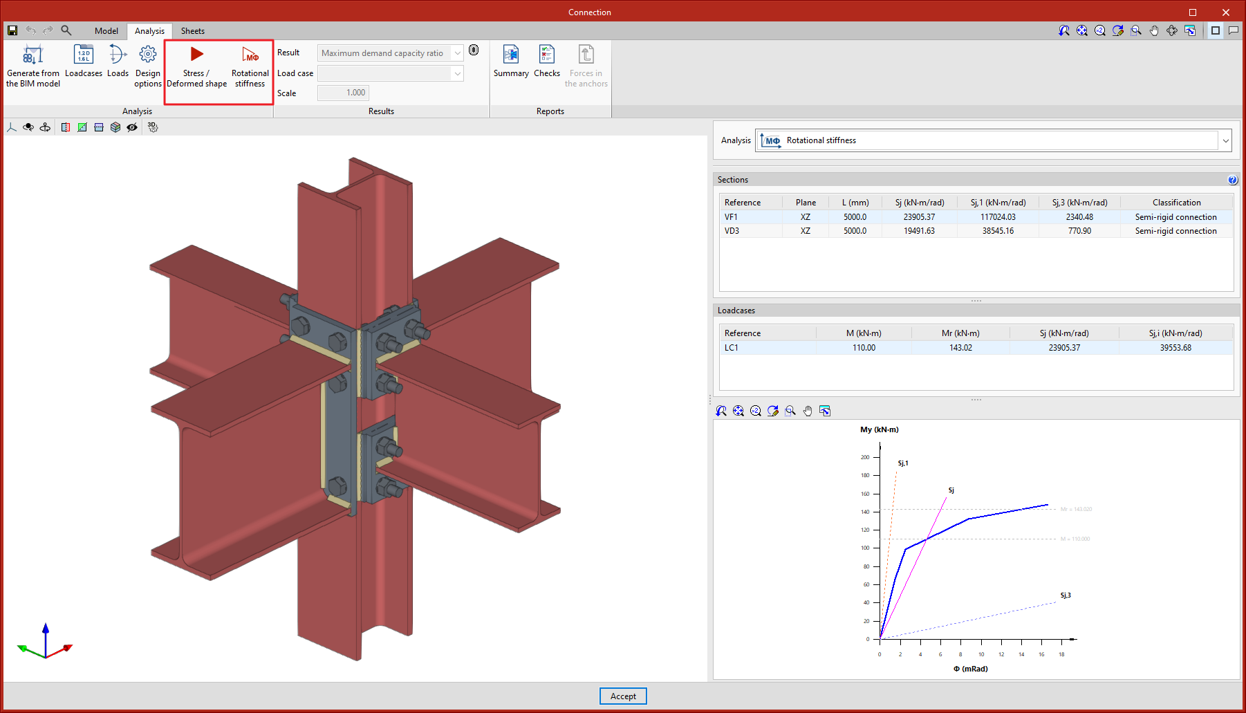
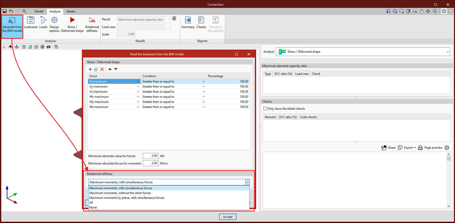
The "Analysis" tab includes the "Rotational stiffness" tool in the top toolbar. If the tool is selected, the rotational stiffness analysis is run.
Furthermore, the "Analysis" tool has been renamed. In previous versions, the "Analysis" button was used to run the stress and deformed shape analysis. This button will now be called "Stress / Deformed shape".
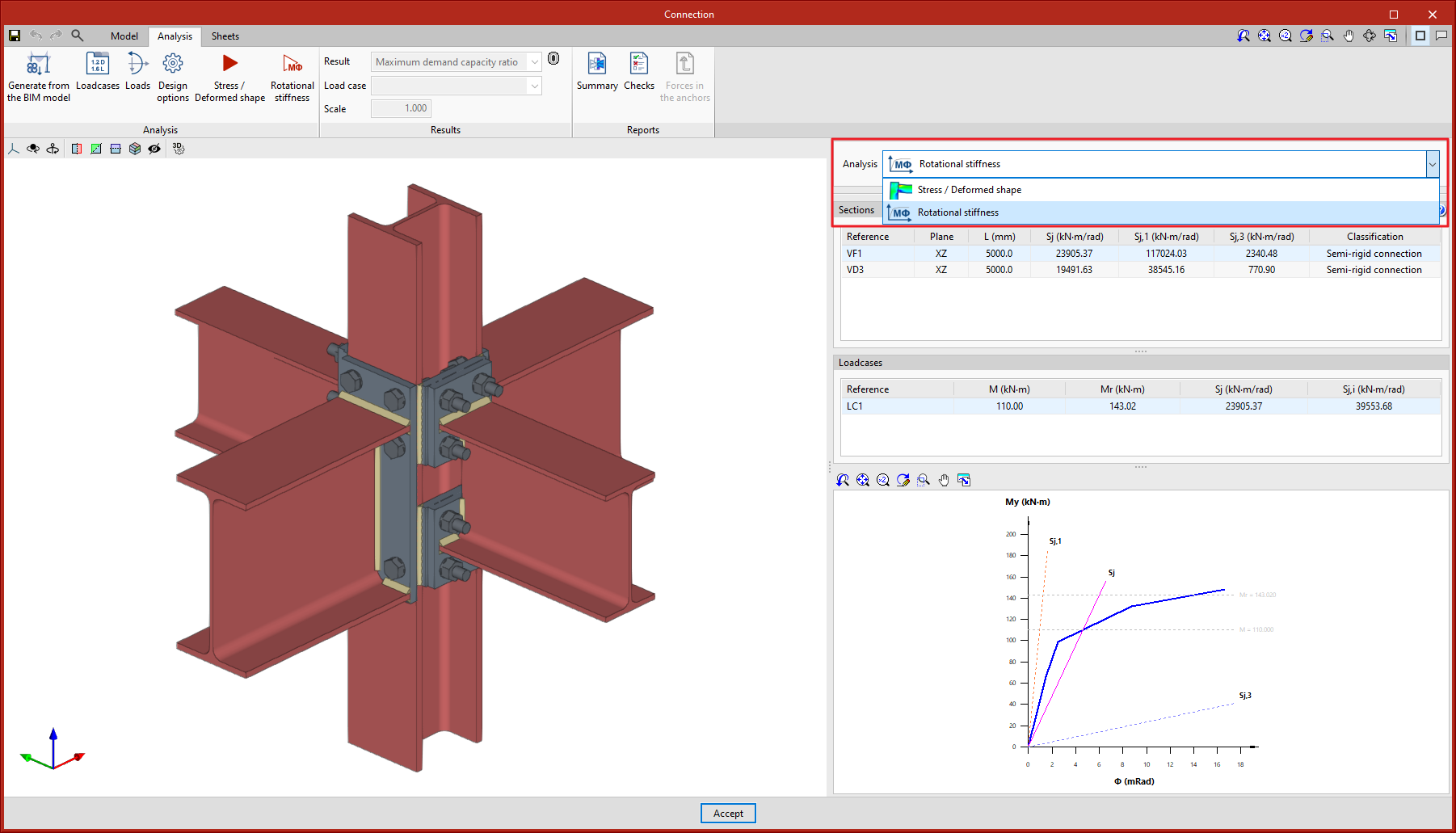
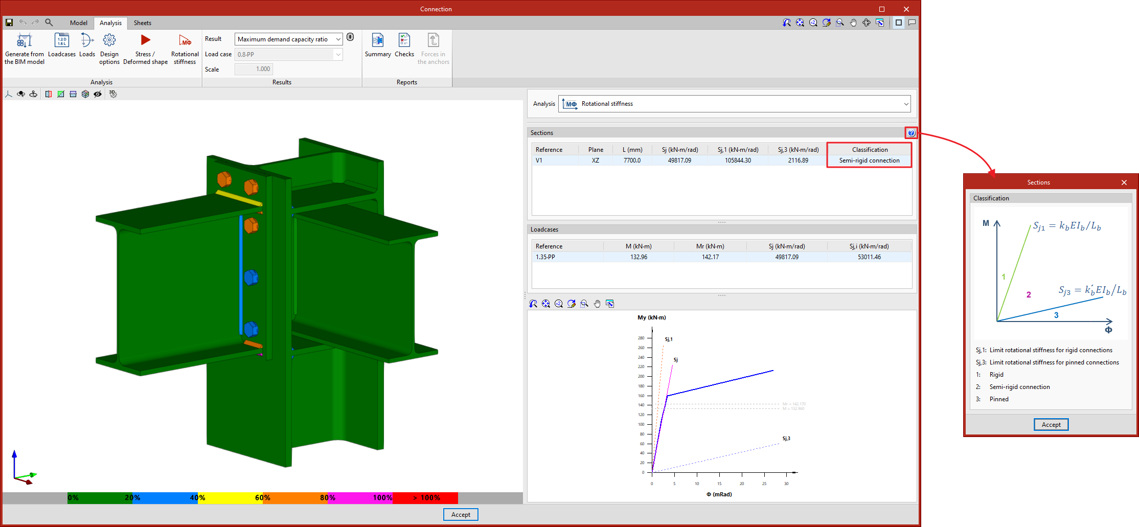
The results can be viewed on the right-hand side of the "Analysis" tab. The top drop-down menu allows users to choose the type of results to be displayed, "Stress/Deformed shape" or "Rotational stiffness". By selecting "Rotational stiffness" the program displays two tables and the "Moment - Rotation" graph.
The first table shows all the analysed bars with their secant stiffness and the connection classification in each plane. The second table shows the load cases analysed for the selected bar. Each load case will indicate the acting moment, the resistant moment, the secant stiffness and the initial stiffness.
The graph shows the curves for "Moment - Rotation", "Acting moment of the selected load case", "Resistant moment", "Ultimate stiffness for rigid connections (Sj,1)" and "Ultimate stiffness for pinned connections (Sj,2)".
As a result of implementing the rotational stiffness analysis, the following changes have been made to existing tools in the program:

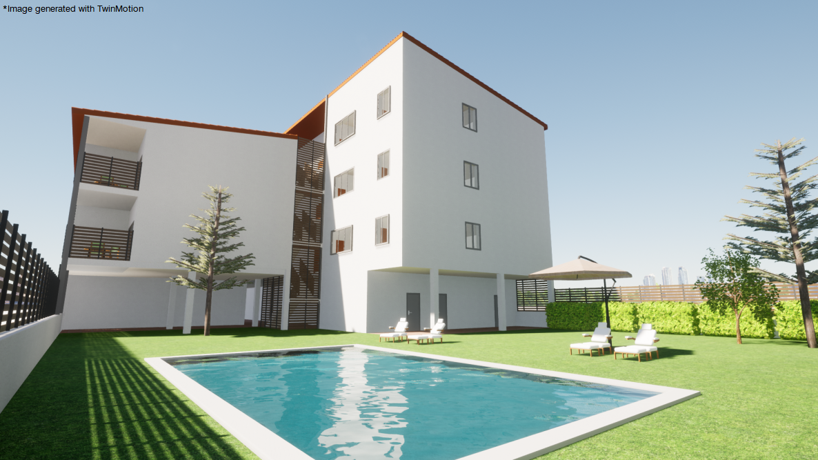
Version 2023.a of all CYPE programs that have the "Print/Save the current view" tool (usually all programs that display graphic information in a window) allows any generated 3D model to be exported in FBX format. This is one of the most common and accepted formats among rendering software (Twinmotion, Enscape, Sketchup+Vray, among others).
Exportation in FBX format is found in the dialogue box that opens when selecting the "Print/Save the Current View" button in any of the programs that include this tool. This feature allows users to export any element that is visible in the current window at that moment in FBX format (as well as elements that have been imported from other programs).
In version 2022.e, the importation of sections from the BIM model has been improved. It is now possible to select or modify the sections for each of the typologies defined in the IFC file.
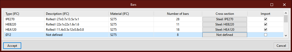
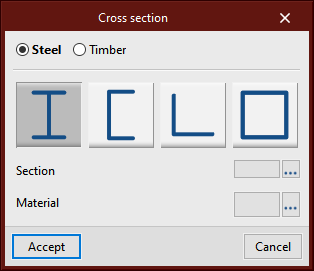
In the "Bars" step of the BIM model import assistant, a list of detected section types is displayed. In the "Cross section" column, the section to be assigned in CYPE Connect will be indicated. By clicking on each cell, the cross section and material selection panel can be accessed.
When possible, the program generates a proposal based on the information available in the BIM model. Users can select the sections they wish to import as well as carry out manual assignments when deemed necessary or when automatic detection has not been possible. The assignment made is saved for subsequent imports.
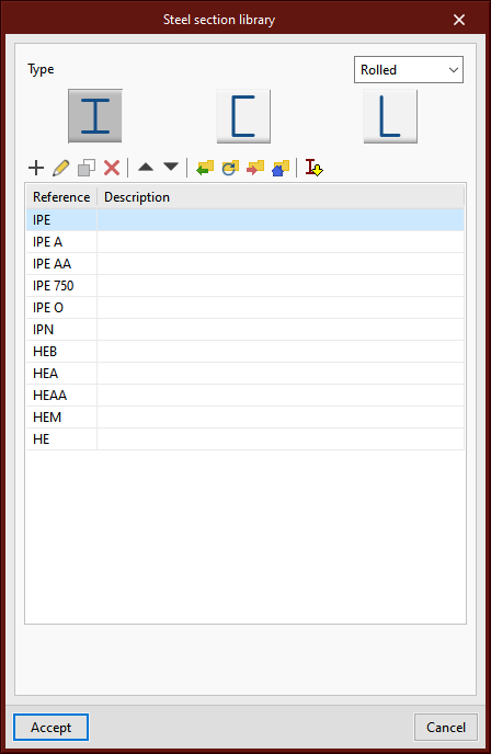
The possibility of using the predefined section libraries that are available in other structure design software such as CYPECAD and CYPE 3D has been incorporated.
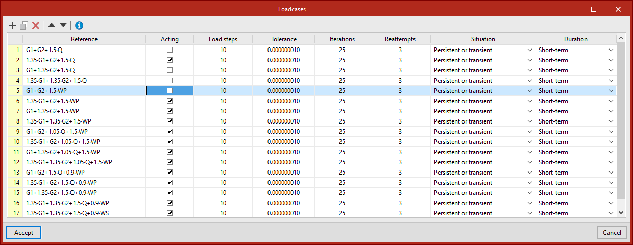
As of version 2022.e, users can select the load cases to be considered when analysing a joint. To do this, the "Acting" column has been added to the table in the "Load case" dialogue box, allowing the desired load cases in the analysis to be activated or deactivated.
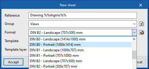
New paper formats have been added to CYPE Connect and Open BIM Layout:
As of version 2022.g, the connections exported to the connections library will also save their defined sheets. Thanks to this implementation, the work spent on making a detail drawing of a connection can be used for similar connections when applying a library connection.
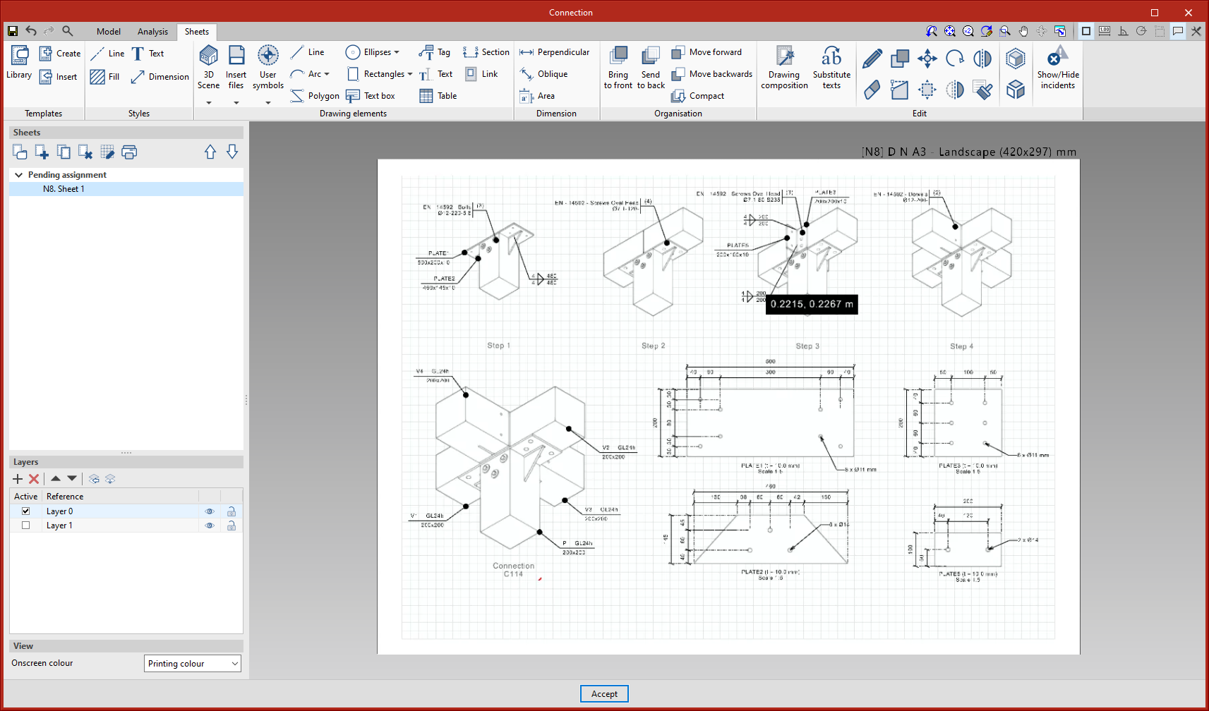
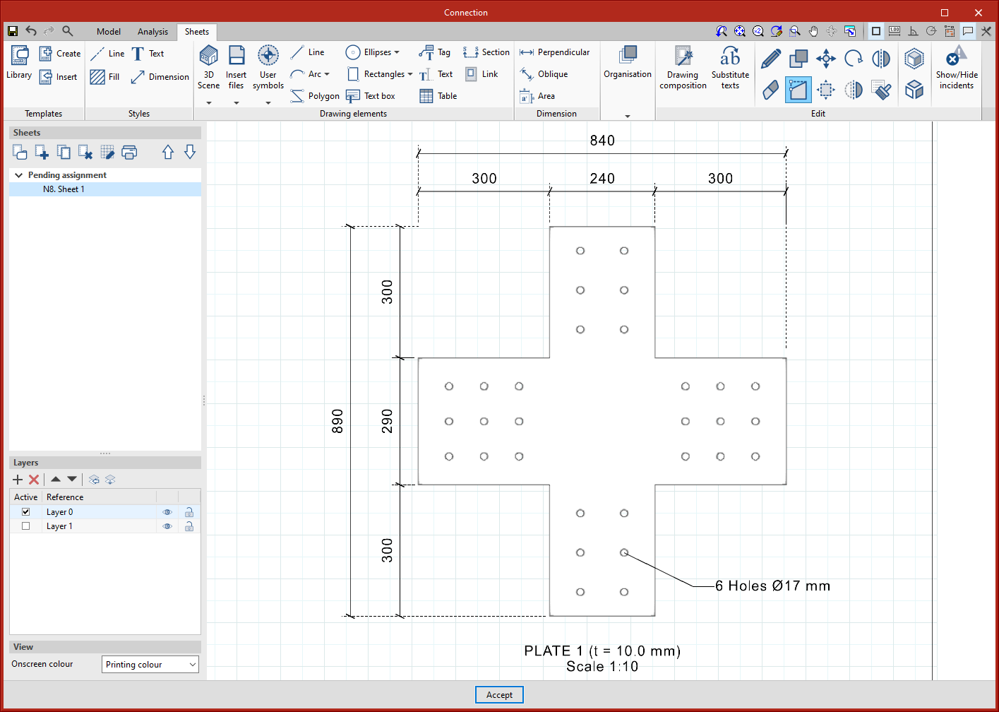
The dimensions defined in each sheet are associated with the geometry of the elements of the scene that have been taken as a reference. This association allows the dimensions of the model to be automatically readjusted in the event of changes in the dimensions of the model.
In the particular case of the tags, this association was already maintained in previous versions, except in the particular case of the tags of the holes in CYPE Connect. As of version 2022.g, this association is maintained, allowing the directrix of the tag to be moved when the position of the relevant hole changes. This is a special case, as the hole itself is not an object in the scene.
The option to export the 3D scenes in sheets in vector graphics format has been implemented in version 2022.g. Up to version 2022.f, these scenes were exported as raster images.
From the scene editing panel, the line style to be used for vector graphics format export can be configured.
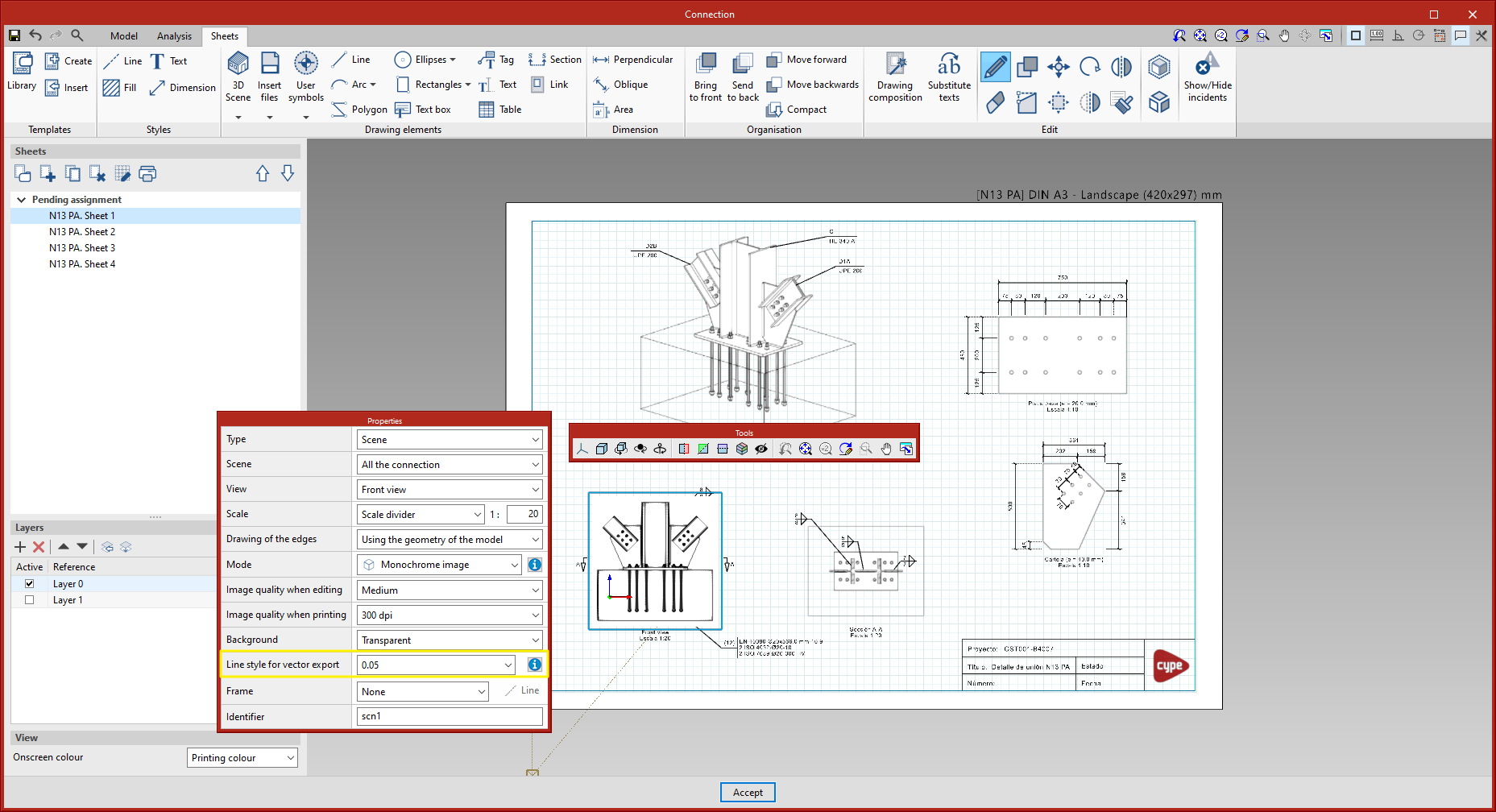
From the 'Print' dialogue box, the scene views can be exported:
The latter option must be selected to export in vector graphics format. In particular, this explains the "when possible" note in the option, a scene view is exported as a vector image if two requirements are met:

As an example, there are two PDF sheets that can be downloaded, which have been exported in vector graphics format.