3D views
3D view of the analytical mode. New view
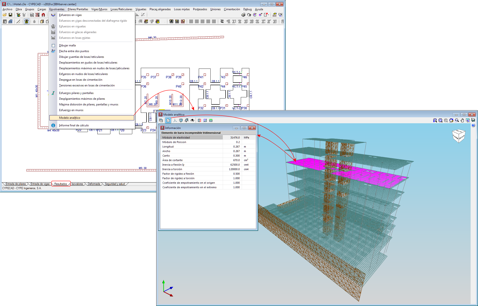
A 3D view of the analytical model has been included in the 2019.f version, which substitutes the old “3D model” view.
The 3D view of the analytical model can be accessed by going to the “Envelope” menu in the “Results” tab. This view is generated when the project is analysed and is always that of the last analysis.
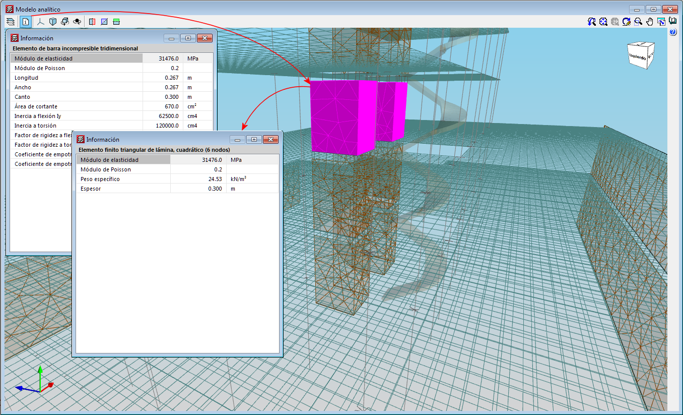
The 3D view has an “Information” tool that is available to users (located in top left hand corner), which displays the properties of the element that users have double clicked on, in a floating window. If users carry out this selection and press the “Ctrl” key at the same time, the floating window remains on screen when another element is selected.
3D view of the analytical model. Export to the BIM model
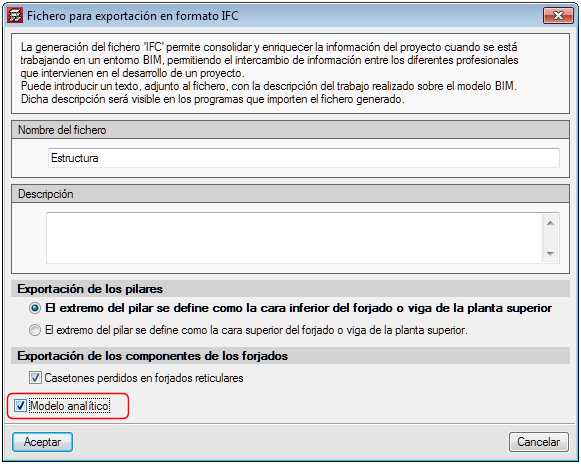
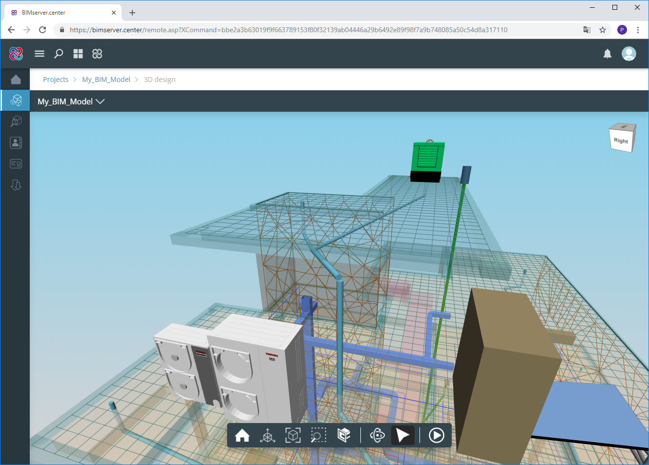
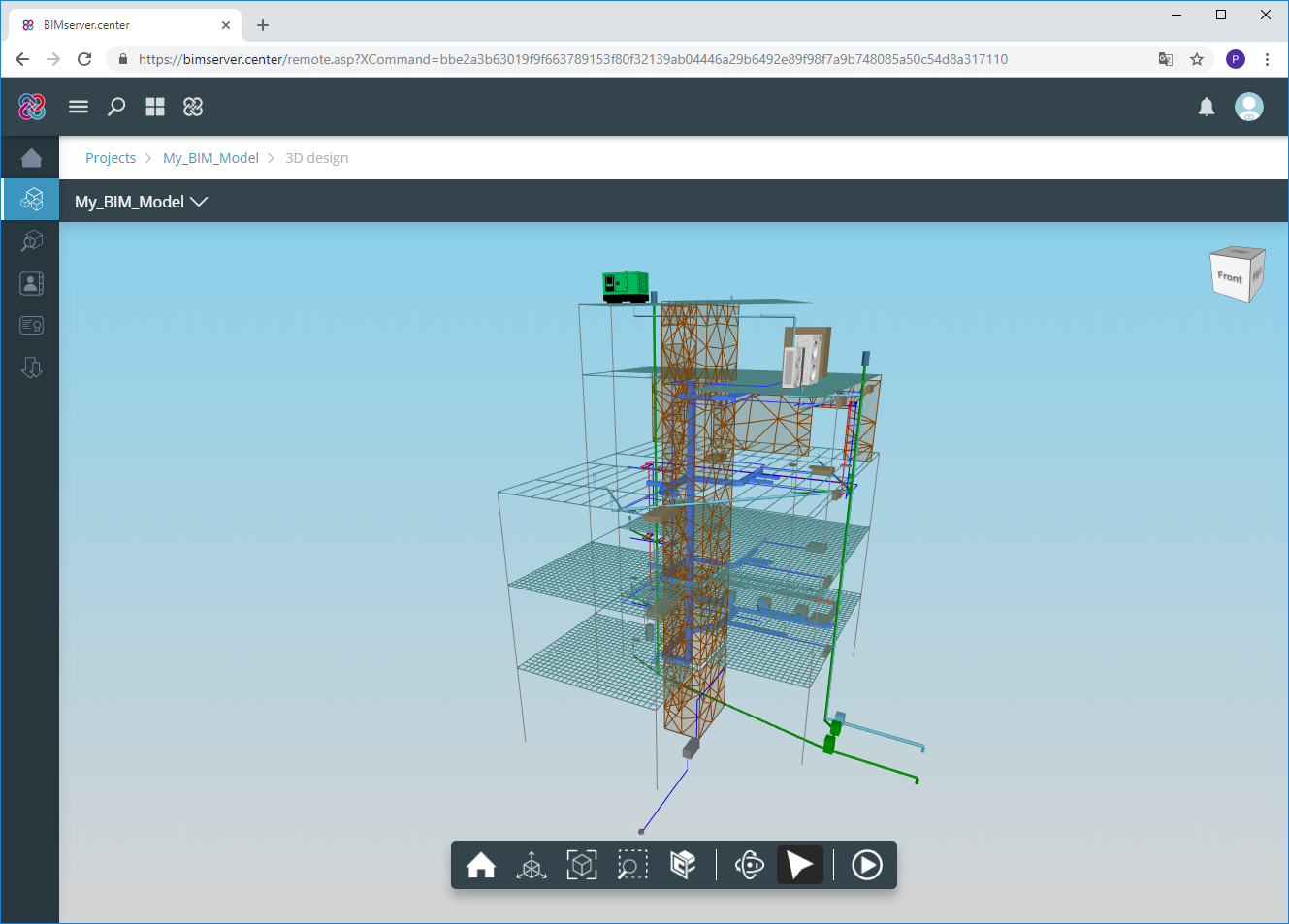
If the project that is being worked on in CYPECAD is linked to an Open BIM model located on the BIMserver.center platform, the new view of the analytical model is also exported to BIMserver.center.
To do so, the “Analytical model” option must be marked in the panel that appears when the information is exported from CYPECAD to the BIM model. This way, the IFC that is generated during the export process will contain the reference to the GLTF file that contains the 3D view of the analytical model containing the information of the elements it is composed of.
Therefore, it is now possible to consult the analytical model and the physical model of the structure using the 3D viewer of the BIMserver.center platform and also from the 3D views of the rest of the applications connected to the BIM model.
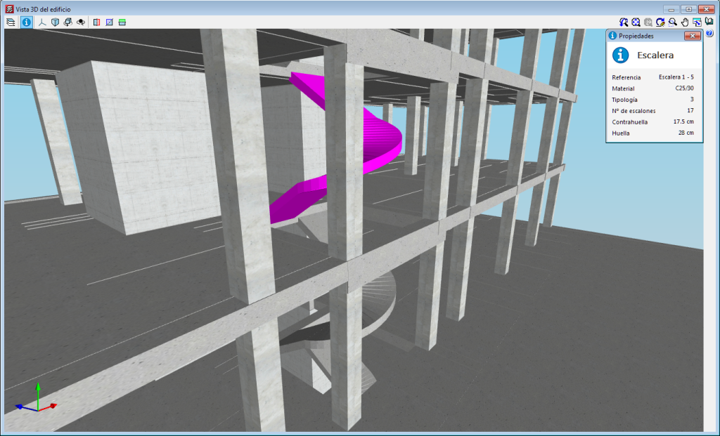
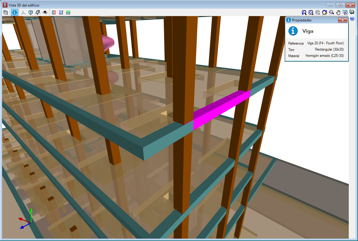
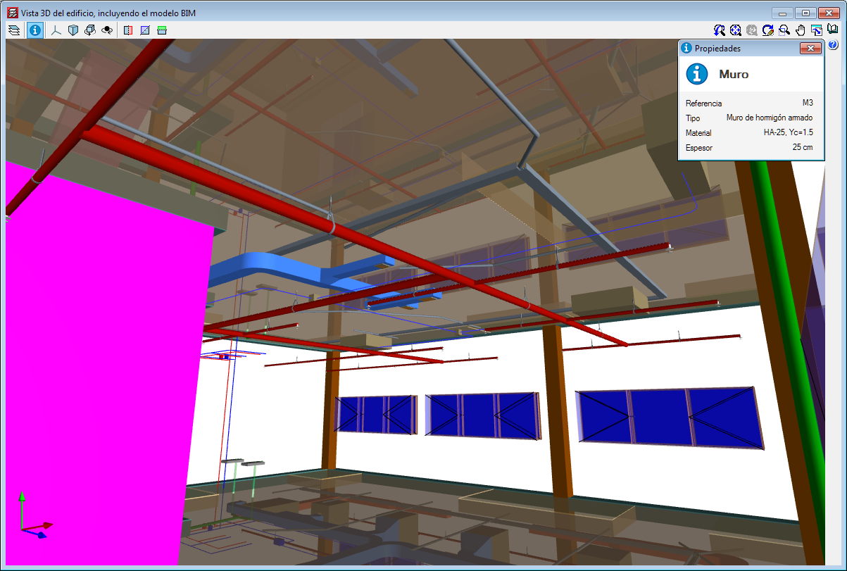
3D view of the structure. Information on the structural elements
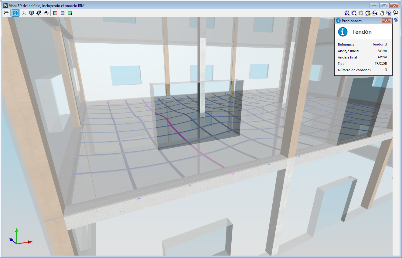
As of the 2019.f version, users can consult the information of the structural elements introduced in the 3D view of the structure shown in CYPECAD, in the 3D view of the BIM model (GLTF) or in the 3D view of the other applications connected to the BIM project. It includes the information on slabs, beams, sloped beams, foundation elements, walls, stairs and post-tensioned tendons.
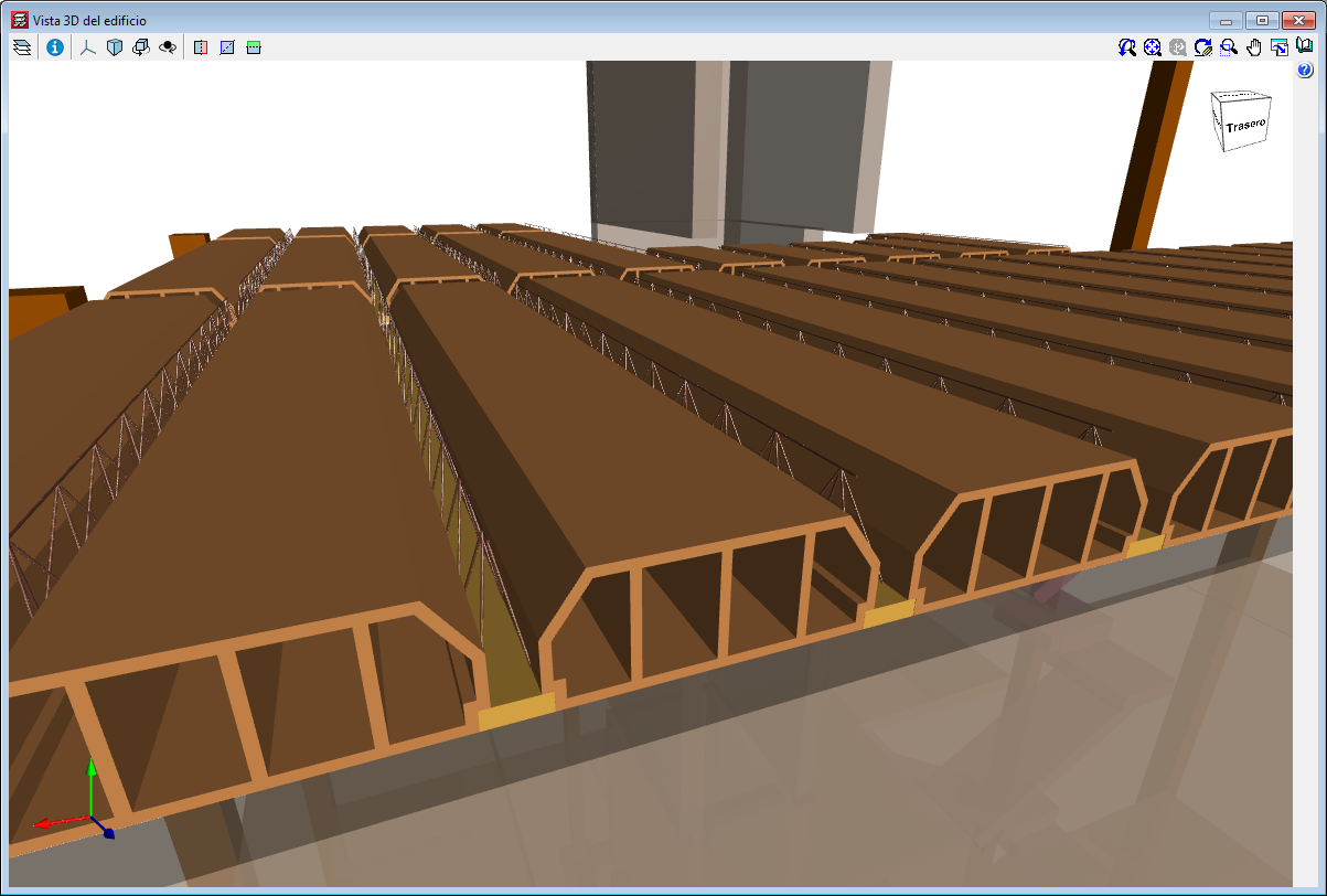
3D view of the structure. New structural elements in the 3D views (joists, forms, composite slab decks and post-tensioned tendons
The 2019.f version provides users with the possibility to include the following structural elements in the 3D view of the structure of CYPECAD and in the 3D view that is exported to the BIM model:
- Joist floor slab components: joists, joist lattice reinforcement and forms.
- Steel decks for composite slabs
- Post-tensioned tendons
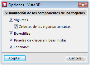
To view these elements in the 3D view of CYPECAD, users must select them in the “Groups > Options - 3D View” menu. A panel appears when the export process is carried out, where users can select the elements.
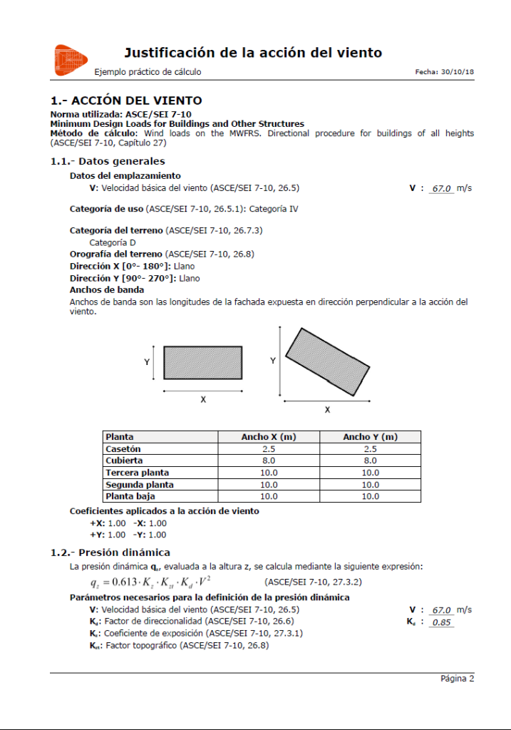
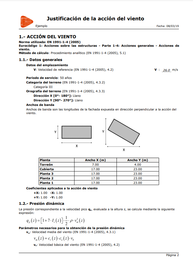
Wind load justification report
The “Wind load justification report” has been implemented in the 2019.f version for the following codes:
- EN 1991-1-4: 2005
Eurocode 1: Actions on structures
Part 1-4: General actions - Wind actions - prNBN EN 1991-1-4: 2005 / ANB (2009)
Annexe nationale pour la Belgique
Eurocode 1: Actions sur les structures
Partie 1-4: Actions générales - Actions du vent - CYS EN 1991-1-4: 2005 / NA (2010)
Cyprus national annex
Eurocode 1: Actions on structures
Part 1-4: General actions - Wind actions - NP EN 1991-1-4: 2005 / NA (2010)
Documento Nacional de Aplicação para Portugal
Eurocódigo 1: Acções em Estruturas
Parte 1-4: Acções Gerais - Acções do vento - SR EN 1991-1-4: 2005 / NB (2007)
Romanian national annex
Eurocode 1: Actions on structures
Part 1-4: General actions - Wind actions - SS EN 1991-1-4: 2005 / NA (2009)
Singapore national annex
Eurocode 1: Actions on structures
Part 1-4: General actions - Wind actions
This report was implemented in previous versions for other design codes and will continue to be implemented for others progressively.
64-bit Version
As of the 2019.f version, CYPE programs (those downloaded from our website and those downloaded from the BIMserver.center platform) are compiled for 64-bit systems. The 64-bit compilation of CYPE software implies the use of the superior features of 64-bit processors and operating systems compared to those of 32 bits.

Please bear in mind that you must have a 64-bit operating system to be able to work with any 64-bit software.
In any case and as a temporary measure, the 2019.f version is available in 64 and 32 bits on the download area of our webpage. The programs that can be downloaded from the BIMserver.center platform are only available in 64 bits. If you have a 64-bit operating system, you can work with either the 64-bit and 32-bit version of our software, although we strongly recommend that you install the 64-bit CYPE software version.
You can see which operating system is installed on your computer by clicking on "Control panel > System".
Since 64-bit microprocessors began to be massively introduced into personal computers from 2003 and from the Windows XP version, Microsoft already offers the two versions of its operating systems (32 and 64 bits). We understand that almost all our users will have computers with 64-bit processors (x64) and 64-bit operating systems.
It could occur that a user may wish to work with a computer with a 64-bit processor but with a 32-bit operating system. It would be very strange if the computer had a 32-bit processor (x86 - computers over 15 years old). If any of these is your case, we advise you to talk to your hardware or software provider to update your situation as soon as possible. However, you can download the 32-bit version and work with CYPE programs that can be downloaded from our website until your situation is up-to-date.
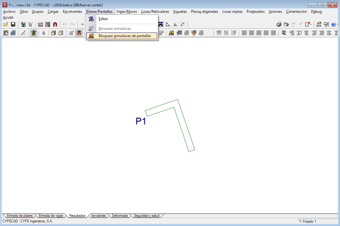
Block shear wall reinforcement
As of the 2019.e version, the reinforcement of reinforced concrete shear walls can be blocked in the same way as is done for reinforced concrete walls.
Blocked shear walls will not undergo any modifications during the design phase.
Wind load justification report
In the 2019.e version, a “Wind load justification report” has been implemented for the following codes:
- ASCE/SEI 7-10 Minimum Design Loads for Buildings and Other Structures (USA)
- NB 1225003-1 Acciones sobre las estructuras. Acción del viento. (Bolivia)
- NCh432-2010 Diseño estructural. Cargas de viento. (Chile)
- NSR-10 Capítulo B.6 - Fuerzas de viento. (Colombia)
- NTC-2017 Normas Técnicas Complementarias para Diseño por Viento. (Mexico)
- REP-04 Reglamento para el Diseño Estructural. (Panama)
- REP-2014 Reglamento para el Diseño Estructural. (Panama)
- RNC-07 Reglamento Nacional de Construcción. (Nicaragua)
This report was implemented for other codes in previous versions and will be implemented for other codes progressively.