Introduction
IFC Builder is a free CYPE app designed for creating and maintaining IFC models of buildings.
Architectural models generated with IFC Builder can be imported by a wide variety of acoustic and energy simulation apps as well as structural and MEP analysis apps linked to BIMserver.center.
Workflows supported by the program
As IFC Builder is an Open BIM tool that is connected to the BIMserver.center platform, it offers different workflow options.
Data entry
Free modelling / with templates
- Defining the architectural elements of the building by freely entering them into IFC Builder.
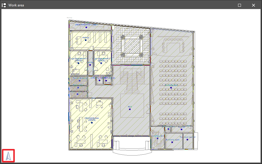
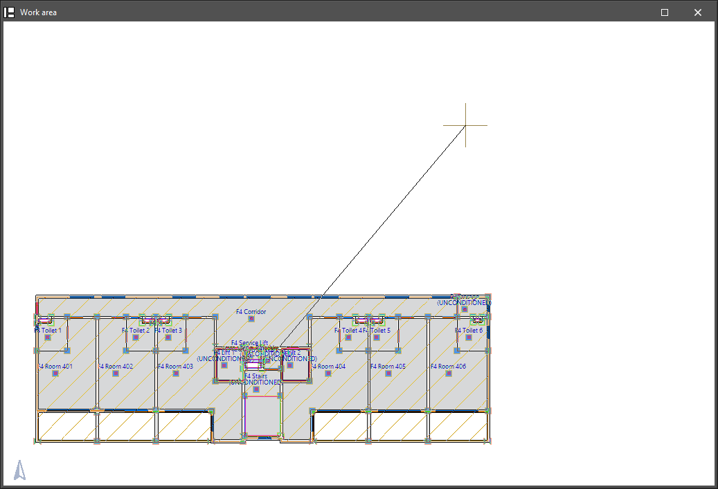
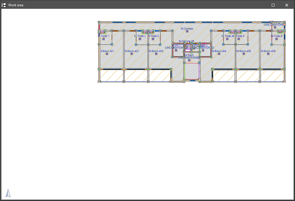
- Defining the architectural elements of the building in IFC Builder from DXF-DWG, DWF, PDF templates or images (.jpeg, .jpg, .bmp, .wmf).
Automatic entry: importing IFC format models
- Importing the model in IFC format with the geometry of a building. This allows users to generate the floor plan of the building and the geometry of walls and partitions, floor slabs and openings (such as windows and doors).
Data output
- Exporting the building model in IFC format.
- Exporting the information generated with IFC Builder to the BIMserver.center platform. This allows authorised project participants to view and export the building geometry to different programs such as CYPECAD, CYPETHERM EPlus, CYPESOUND, CYPEPLUMBING, CYPELEC Electrical Mechanisms, CYPELEC Distribution, CYPEGAS, CYPEHVAC, CYPEHVAC Radiant Floor, CYPELUX, CYPEFIRE, CYPEFIRE Hydraulic Systems and CYPETEL Wireless, among others.
Work environment
The IFC Builder interface features a work environment that makes building modelling quick and easy, with a system of dockable windows that can be customised to adapt the workspace to the project's needs.
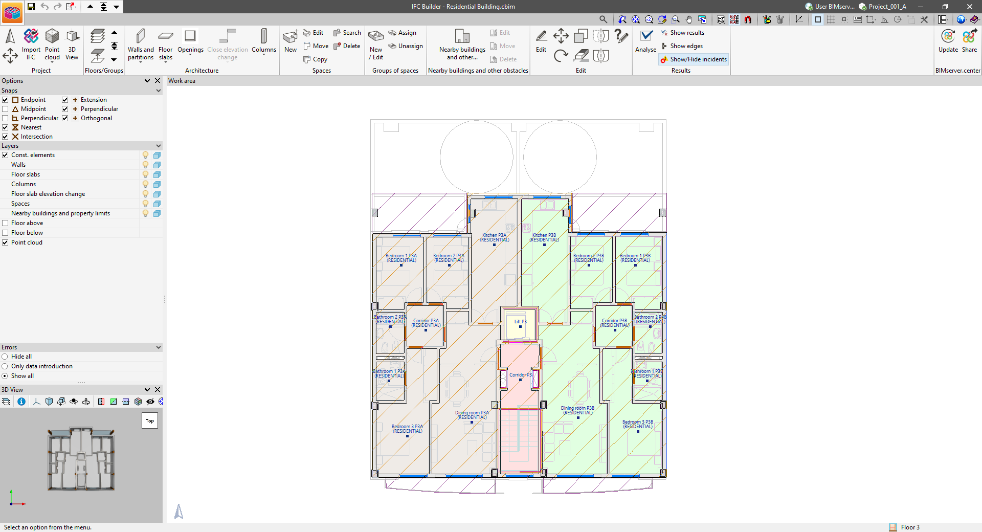
The program interface displays the following:
- A top toolbar, which contains the tools for managing the project characteristics, entering and editing the building's construction elements, entering and grouping the spaces, checking the geometry, and exporting the model to BIMserver.center;
- The modelling area on the right-hand side of the screen, where all elements of the project are entered, edited and displayed floor by floor;
- Several panels on the left-hand side with tools to configure the snaps of the elements in the model, manage the visibility of the layers, hide or show errors and display the 3D view.
Defining the general characteristics of the project
The following options can be found in the "Project" group of the main toolbar:

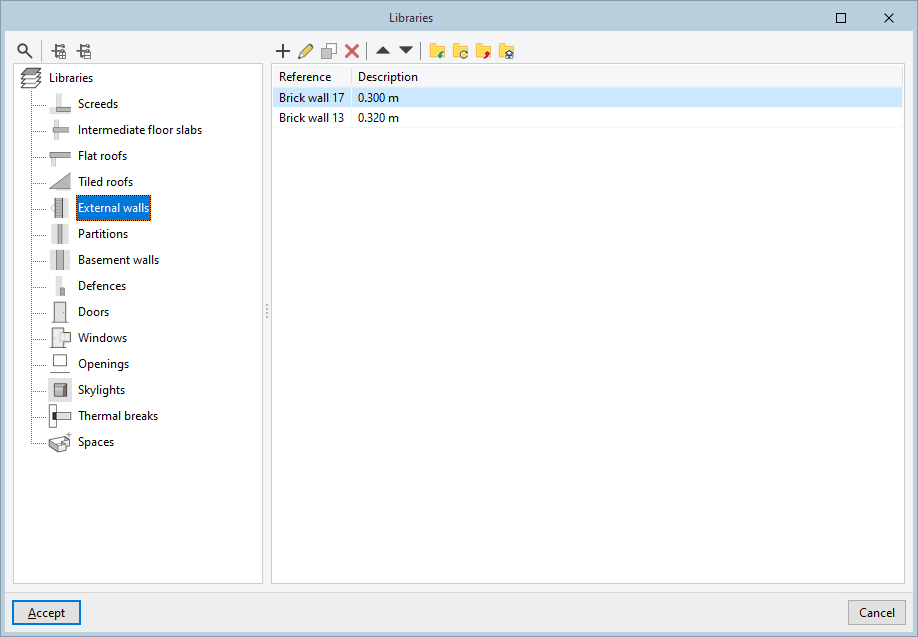
Libraries
Manages the libraries of types defined for the components of the model.
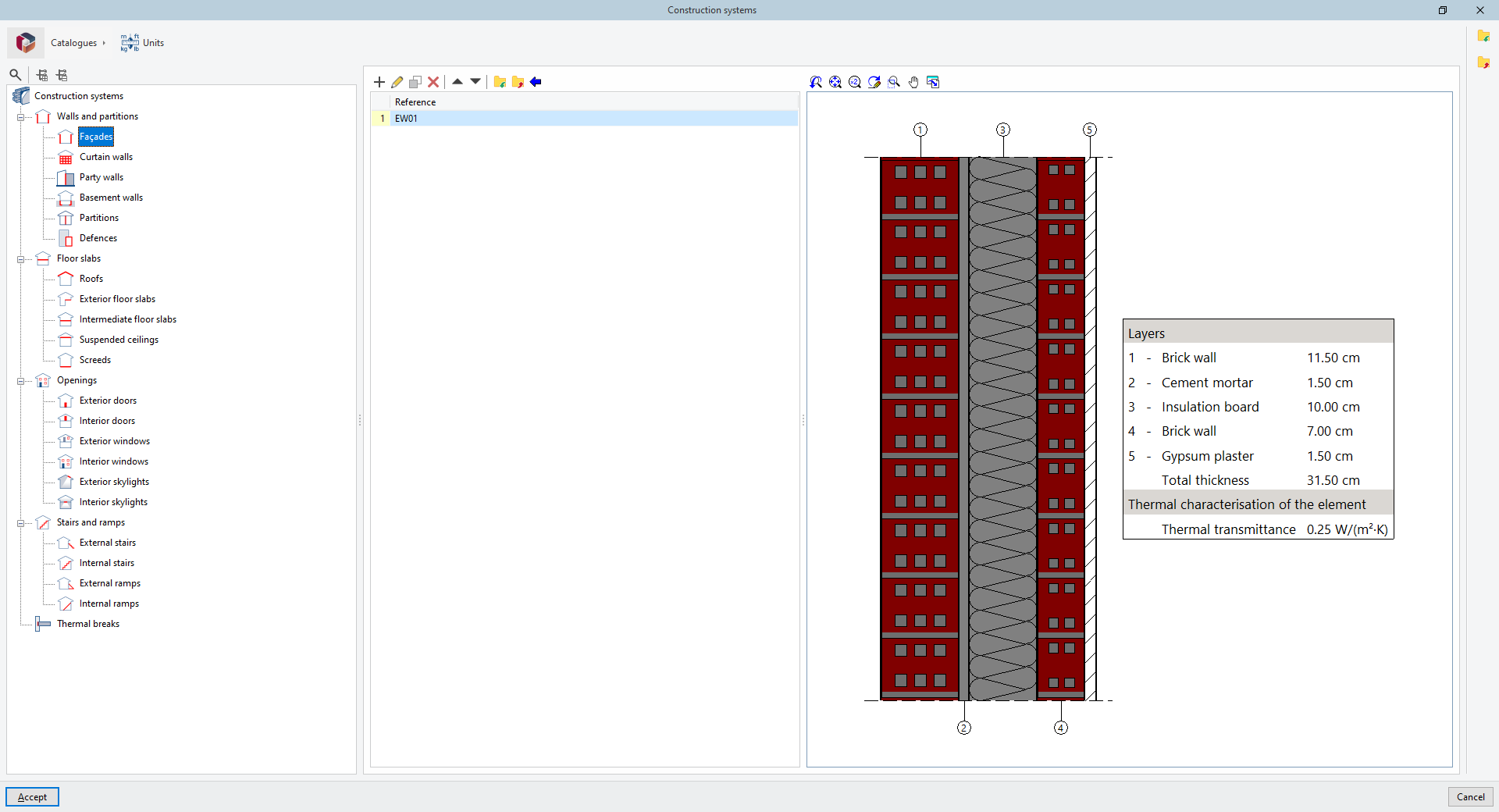
Construction systems
Defines the construction systems for the components of the model. It includes the possibility to download and use products from manufacturer's catalogues.
Orientation
Allows users to enter the orientation of the model by indicating the direction and the north direction. The icon showing the north direction is located in the bottom left corner of the work area. By default, north points to the top of the screen.
Move the building
Moves the entire building as a whole, including all floors, to the specified coordinates.
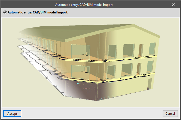
Import IFC
Launches the "Automatic entry. CAD/BIM model import" assistant. Once completed, it replaces the geometry of the model with the geometry imported from the IFC file.
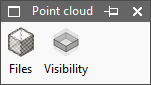
Point cloud
Imports and manages the visibility of point cloud files.
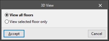
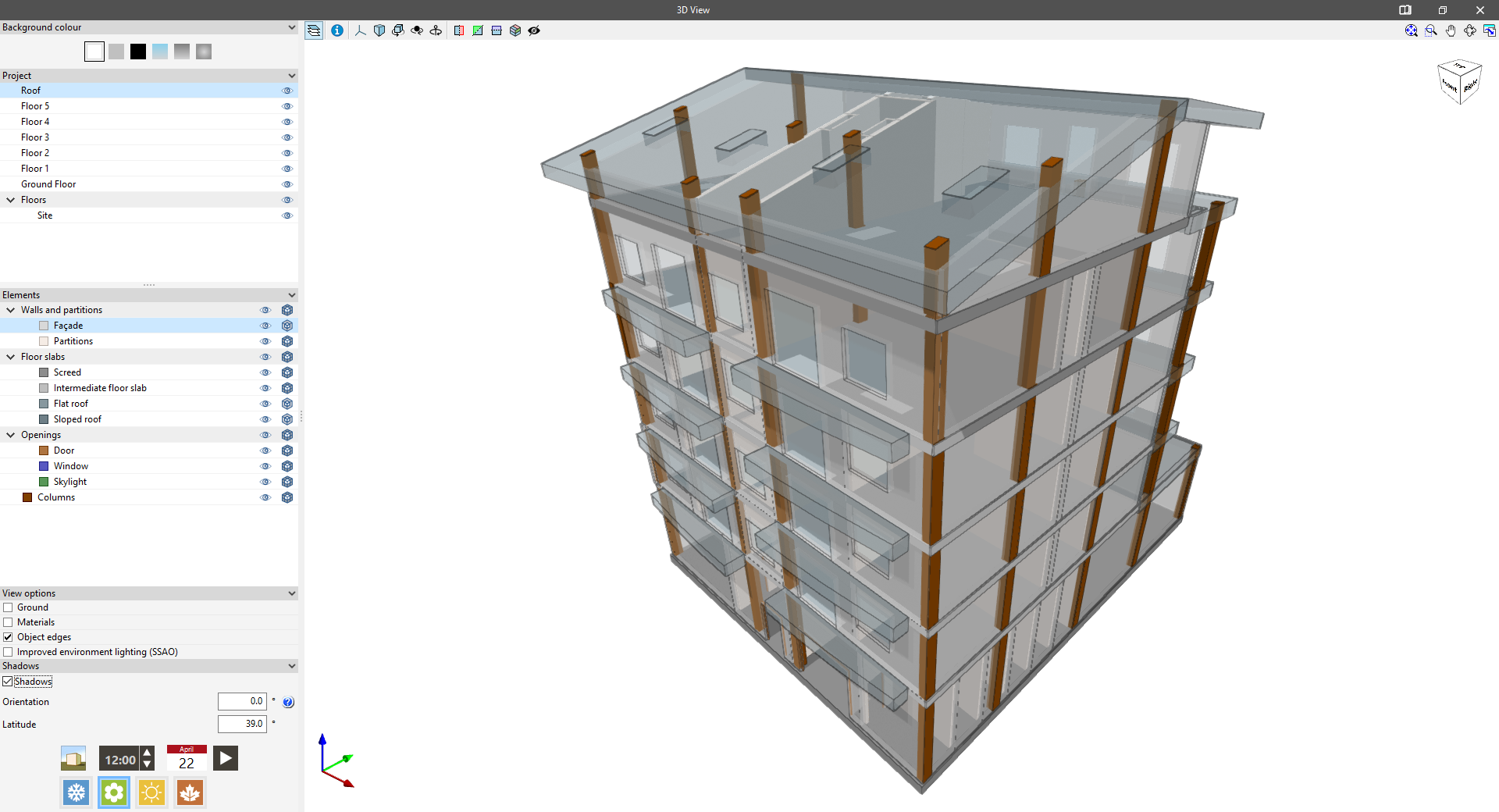
3D View
Displays a three-dimensional view of the model and allows users to choose between:
- View all floors
- View selected floor only
- Draw the ceiling of the floor (optional)
Importing the model from IFC files
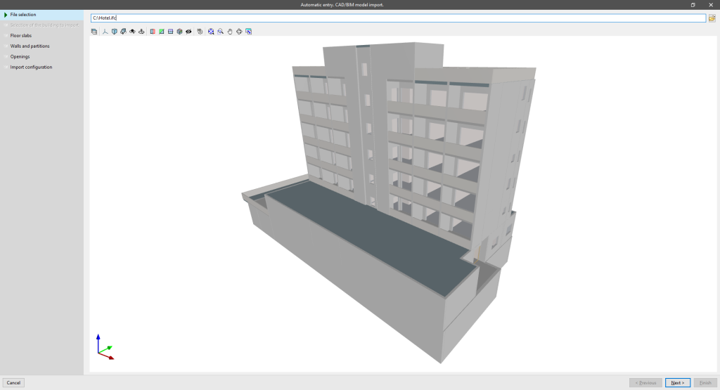
When creating a new job in IFC Builder, or by using the "Import IFC" option in the "Project" group of the main toolbar, users can import a model in IFC format generated by CAD/BIM programs, such as Allplan®, Archicad®, and Revit®. This allows IFC Builder to access data from programs that have BIM (Building Information Modeling) technology and automatically incorporate the building's construction elements.

When using this option, the program launches the “Automatic entry. CAD/BIM model import" assistant, which presents the following data definition sequence:
File selection
Allows an IFC file to be selected from its location on disk.
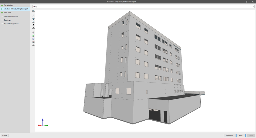
Selection of the building to import
If the IFC file includes information on several buildings, the program requires users to select the building to be imported.
The IFC class interpreted in this step is the following:
- IfcBuilding
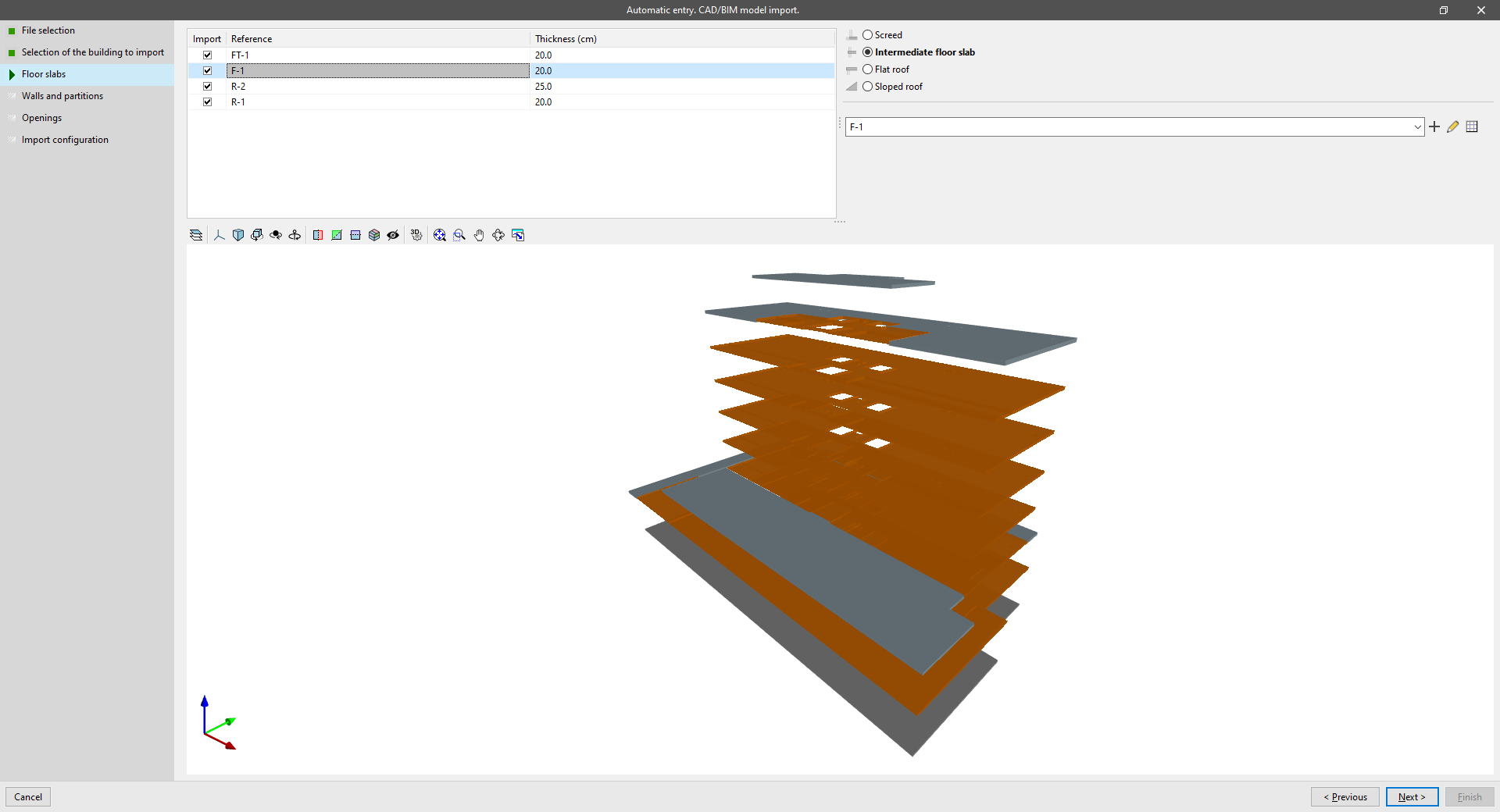
Floor slabs
Allows users to view the reference and thickness of the slabs defined in the IFC file, to select the slabs to be imported, and to create and assign their typologies in IFC Builder.
The IFC class interpreted in this step is the following:
- IfcSlab
Walls and partitions
Allows users to view the reference and thickness of the walls and partitions defined in the IFC file, to select the walls and partitions to be imported, and to create and assign their typologies in IFC Builder.
The IFC classes interpreted in this step are the following:
- IfcWall
- IfcWallStandardCase

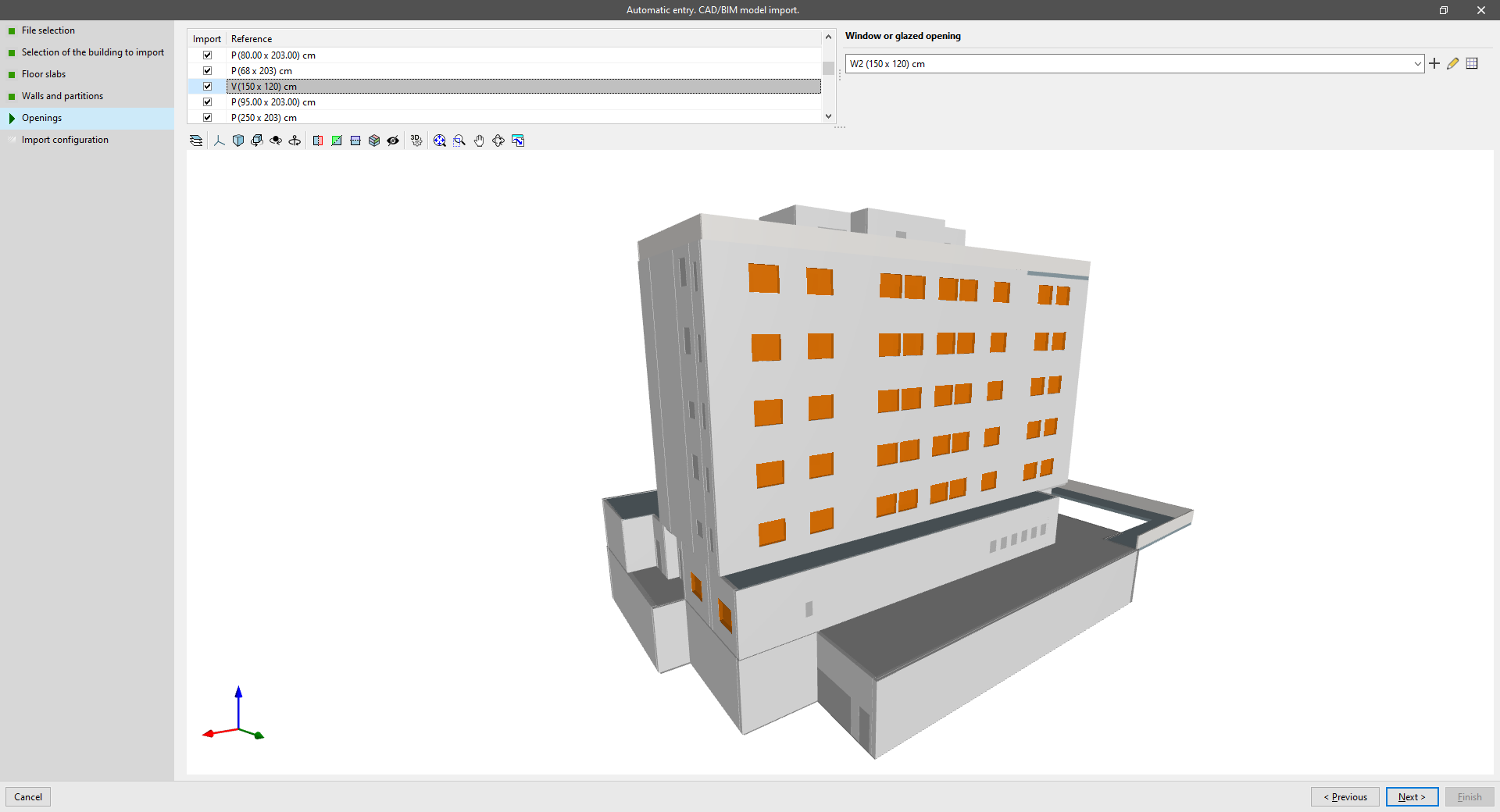
Openings
Allows users to view the reference of the openings defined in the IFC file, to select the openings to be imported, and to create and assign their typologies in IFC Builder.
The IFC classes interpreted in this step are the following:
- IfcDoor
- IfcWindow
- IfcOpeningElement
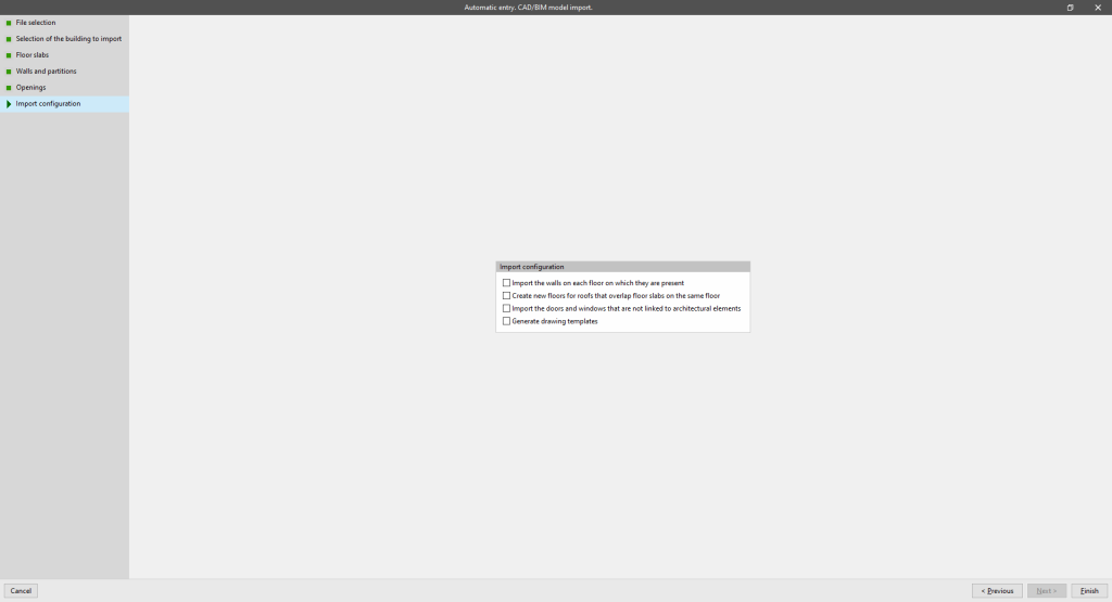
Import configuration
Allows users to activate the following import configuration options:
- Import the walls on each floor on which they are present (optional)
- Create new floors for roofs that overlap floor slabs on the same floor (optional)
- Import the doors and windows that are not linked to architectural elements (optional)
- Generate drawing templates (optional)
The reading of IFC files and the import of their data through this assistant is unidirectional, and an update of the data cannot be performed if the information in the IFC file changes. However, in this case, a new IFC import could be carried out.
Reading point clouds
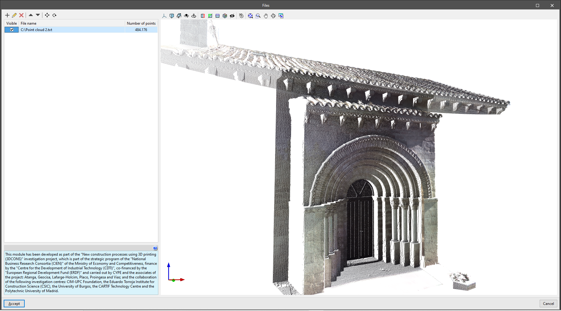
IFC Builder can read a representation both in 3D and on plan from point cloud files (*.pts; *.ptx; *.txt; *.xyz), which can be used as a support to model reality quickly and accurately from a BIM environment.
A point cloud is the result of one or more 3D laser scans consisting of a set of vertices in a three-dimensional coordinate system, usually defined by "x", "y" and "z" coordinates, and sometimes incorporating additional data such as colour using RGB values.

The "Point cloud" menu in the main toolbar of the program's general interface contains the following options:
- Files
- Visibility
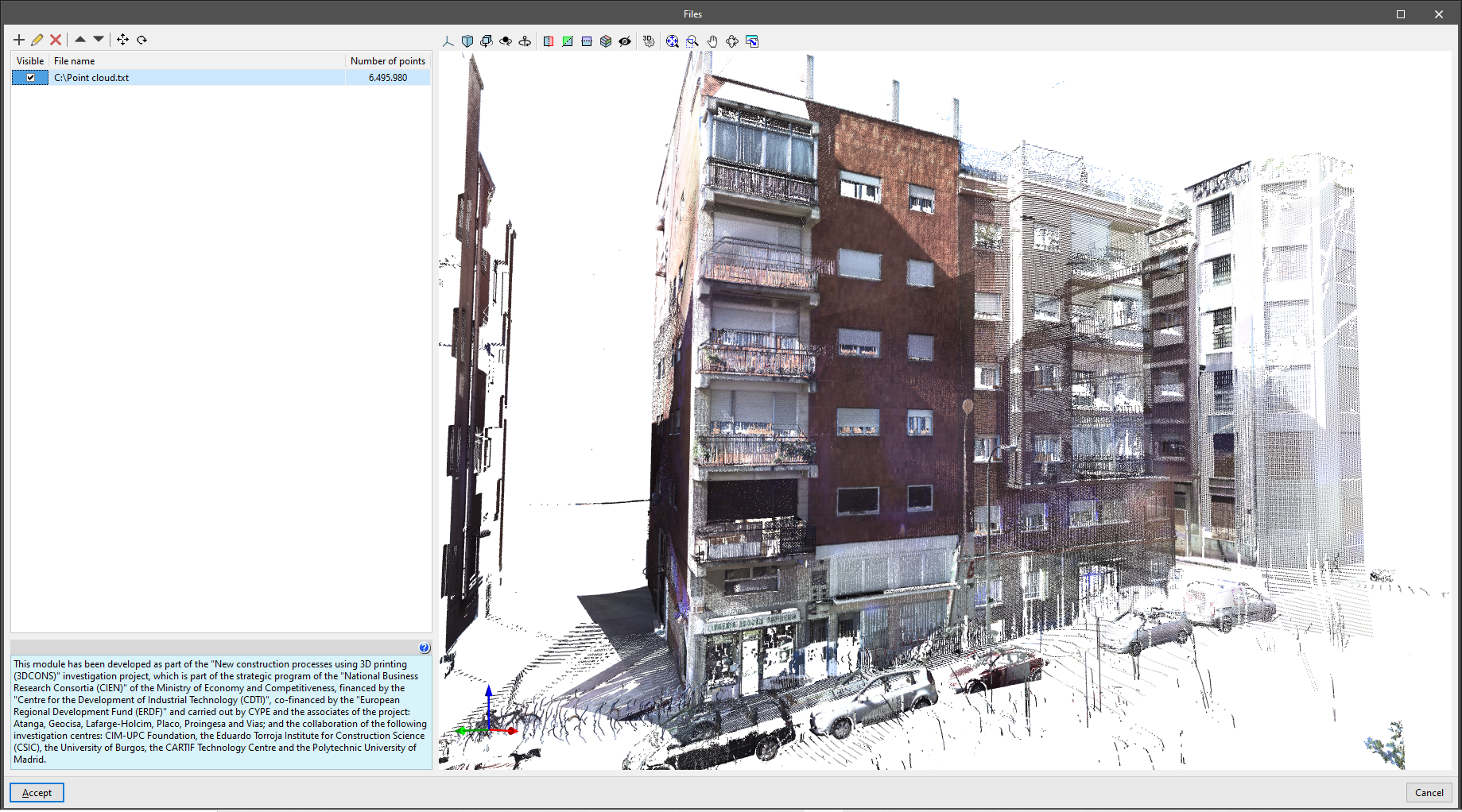
Files
Allows users to select PTS, PTX, TXT or XYZ point cloud files at their location on disk and load them into the program, defining the following information:
- File name
- Show in monochrome (optional)
The loaded point cloud files are displayed in a table with the following parameters:
- Visible
- File name
- Number of points
As added tools, the point cloud can be moved and rotated.
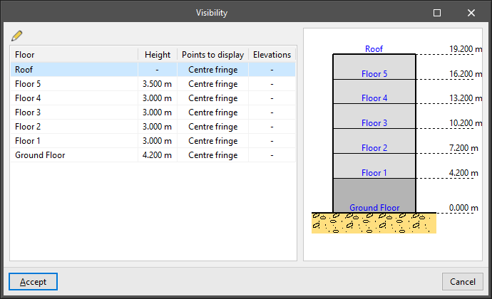
Visibility
Manages the visibility of the points in the point cloud files on the different floors of the building. The following information is shown in the table:
- Floor
- Height
- Points to display (All points / Centre fringe / Height range)
- Elevations (only for "Height range")
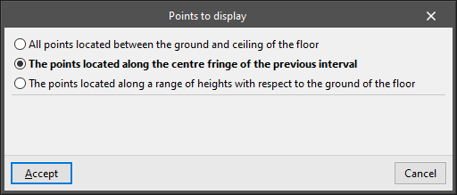
If each floor is edited, the "Points to display" are selected. These points can be:
- All points located between the ground and ceiling of the floor
- The points located along the centre fringe of the previous interval
- The points located along a range of heights with respect to the ground of the floor
- Initial height
- Final height
In this way, the visible points of the point cloud can be used as a visual reference when entering the elements of the model floor by floor.
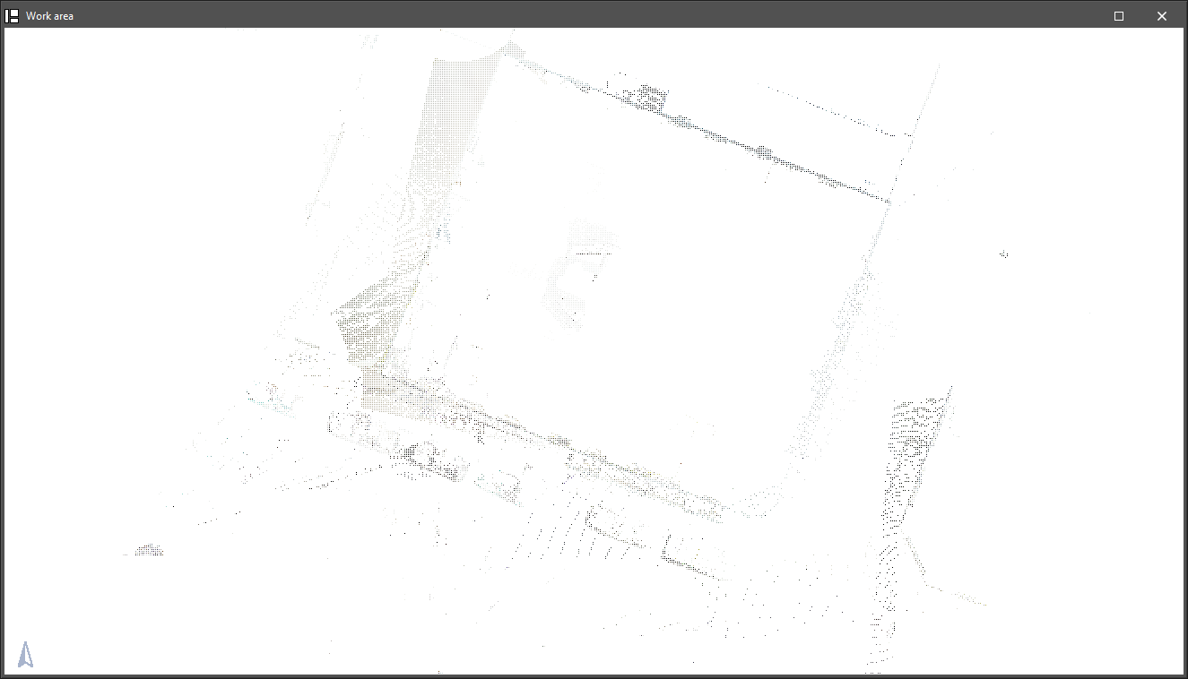
The 3DCONS project aims to bring 3D printing technologies to the construction industry, both in the field of new construction and in the renovation and restoration of cultural heritage, using point cloud technologies for the reading of existing buildings.
Defining floors and groups
The following options can be found in the "Floors/Groups" group in the main toolbar:

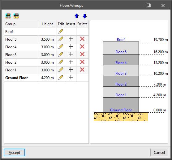
Floors/Groups
Allows users to define the floors and groups of the building.
A table with the following information appears on the left side of the "Floors/Groups" window:
- Group
Reference of each group of floors. - Height
Height of the floors belonging to each group. - Edit
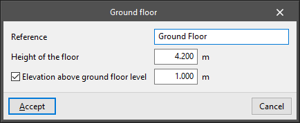
Allows the characteristics of each group of floors to be edited:- Number of floors in the group (except ground floor and roof floor)
- Height of each floor
- Reference for each floor
- Elevation above ground floor level (ground floor only)
This option allows users to specify an elevation above the ground level with respect to the base plane of the ground. This allows a semi-buried basement to be defined.
- Insert
Allows a group of floors above or below ground level to be inserted in the position immediately above. - Delete
Deletes the group of floors.
By default, the program always presents a ground floor and a roof floor.
The following tools can be found at the top:
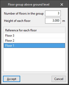
- Floor group above ground level / Floor group below ground level
Allows a floor group to be entered above or below ground level by specifying the following parameters:- Number of floors in the group
It can be a group of one floor or a group of several floors greater than 1 if users want to define a set of several floors that are exactly the same. - Height of each floor
Corresponding to the distance between the top face of the floor slab entered on each floor and the top face of the floor slab on the floor above it. - Reference for each floor
- Number of floors in the group
- Move the building up a floor / Move the building down a floor
These options allow the building to be raised or lowered one storey by changing the position of the base plane of the ground.
On the right-hand side, there is a schematic display of the floors of the building, the ground plan and the reference and height of each floor relating to it.
Copy to another group
Allows the elements of another floor group to be copied over the current group, i.e. the one the user is currently in. If data already exists in the group to be copied, this data will be lost.
This option is very useful when the elements of one group are almost the same or very similar to those of another group. Once the copy has been made, the appropriate modifications can be made.
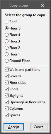
The option opens the "Copy group" window, in which the following aspects are configured:
- Select the group to copy
- Activate or deactivate the types of elements to be copied:
- Walls and partitions
- Screeds
- Floor slabs
- Roofs
- Skylights
- Openings in floor slabs
- Columns
- Spaces
Up a group/Change group/Down a group

These tools allow users to modify the group of floors visible in the working area.
The options "Up a group" and "Down a group" allow users to display the group of floors immediately above or below the one visible on the screen, while from "Change group" they can directly select the group of floors they want to display.
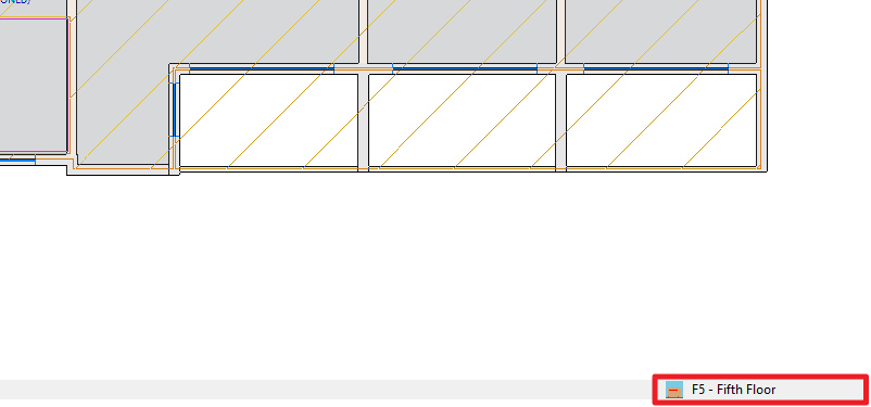
The floor group reference visible on the screen is displayed in the lower right corner of the program's general interface.
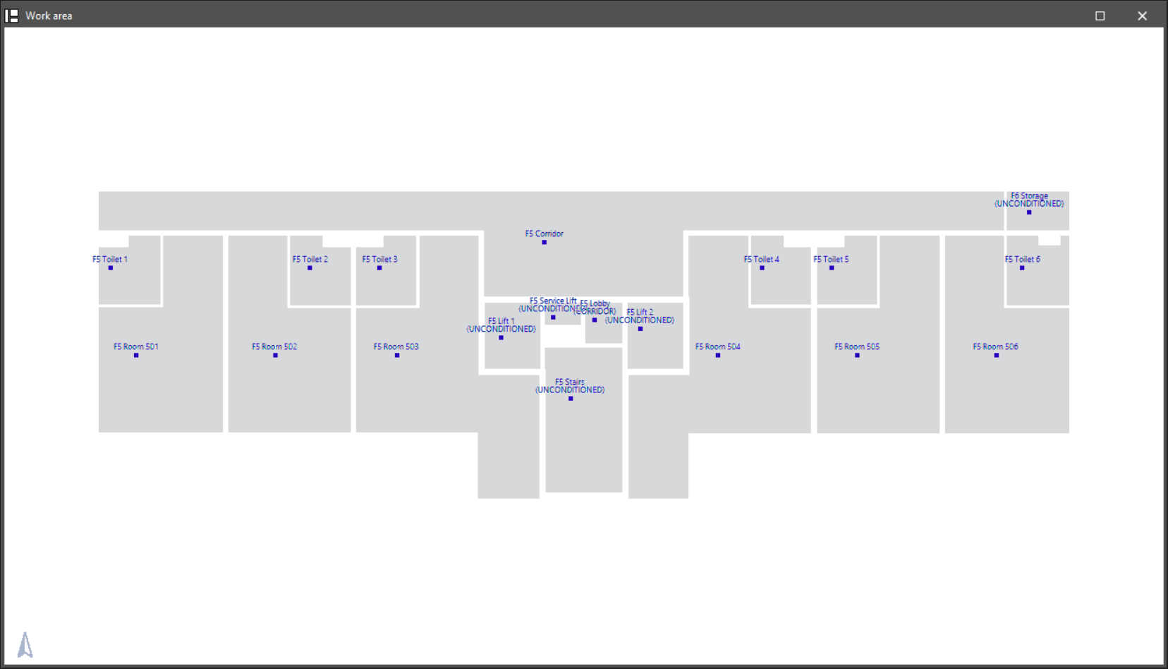
Entering spaces
The following options are available in the "Spaces" group of the main toolbar:

These options allow the building spaces to be entered and edited after the architectural elements have been defined.
The tool for entering new spaces is as follows:
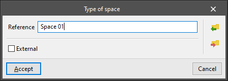
- New
Allows a new space to be entered into the model. The following parameters must be defined:- Reference
- Exterior (optional)
Indicates that the space entered is an exterior space, such as a balcony or terrace.
The space editing tools are as follows:
- Edit
Edits or consults the type and characteristics that have been associated with the selected space. - Move
Moves the space definition point. - Copy
Copies the characteristics of one space to another. - Search
Searches for a space by entering the text of its reference or part of it. - Delete
Deletes one or more spaces.
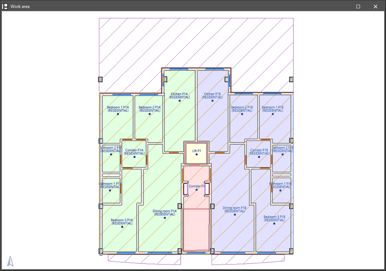
Grouping spaces
The following options are available in the main toolbar in the "Groups of spaces" group:

These tools allow users to group previously entered spaces according to their characteristics to carry out the zoning of the project. This zoning can then be imported into the analysis programs.
The tools for defining groups of spaces are as follows:
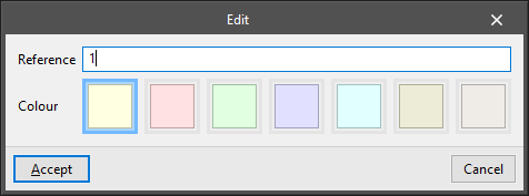
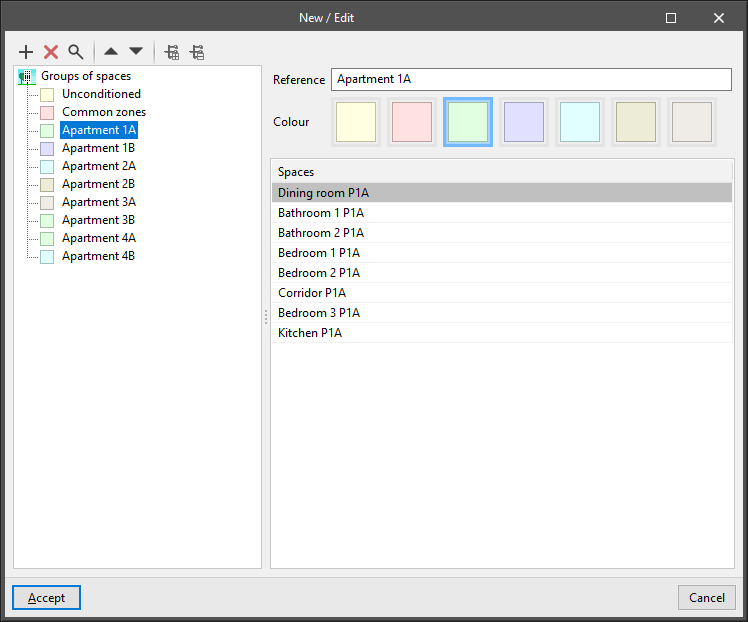
- New / Edit
Allows users to access the table of groups of spaces. Several levels of space groups can be created through a group hierarchy system. On the right, the table shows the spaces assigned to each group. Each space group has the following parameters:- Reference
- Colour
- Assign
Allows users to select a group of spaces and assign it to one or more spaces previously entered in the model.
- Unassign
Allows users to unassign a group of spaces to the selected spaces in the model.
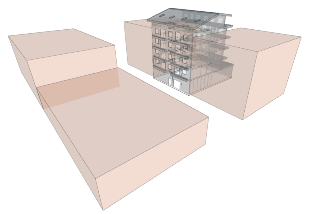
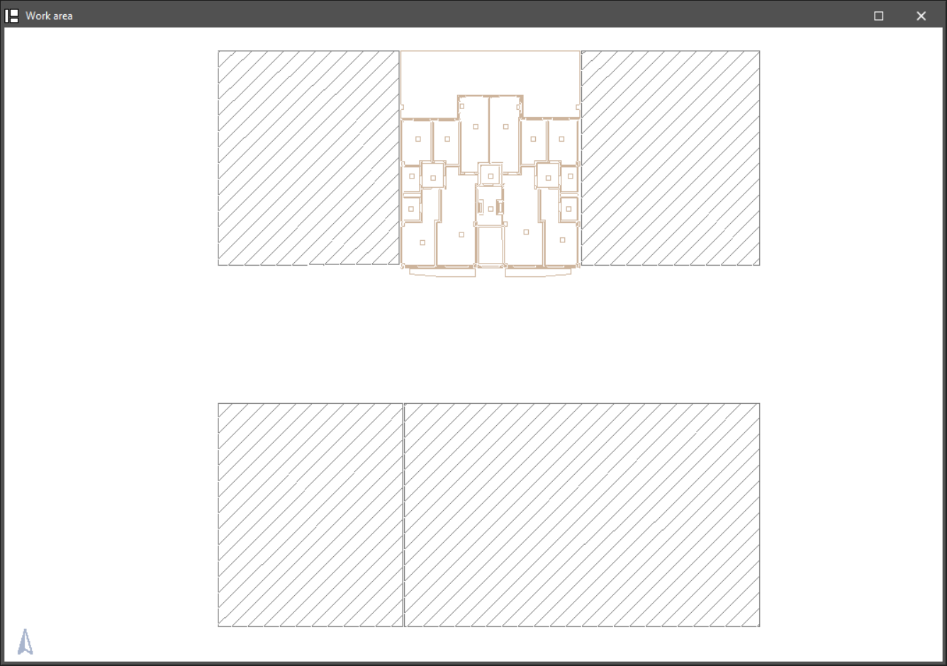
Defining nearby volumes
The "Nearby buildings and other obstacles" menu is located in the "Building elements" group of the main toolbar:

The options in this menu can be used to define volumes close to the building, such as other nearby buildings, which can later be considered in simulations carried out by other programs, especially due to the calculation of shadows cast by them.
The tool for entering nearby volumes is as follows:
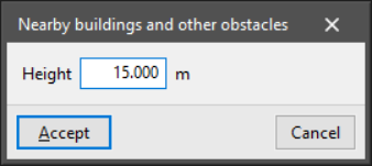
- Nearby buildings and other obstacles
Allows users to enter a nearby volume to simulate the existence of a nearby building or other obstacle. The volume outline can be entered on any floor.
This tool requires the definition of the following parameter:- Height
Height of the volume with respect to the ground plane.
- Height
The program will generate a volume by extruding the contour entered on the plan with the defined height and supported on the base plan of the ground.
The tools for editing nearby volumes are as follows:
- Edit
Modifies the height of the selected volume. - Move
Changes the plan layout of a nearby volume by modifying the position of the vertices of its outline. - Delete
Deletes one or more selected volumes.
Editing tools
The following options are available in the "Edit" group of the main toolbar:

The operation of each of these tools is described below.
| Edit | Allows users to select an element of the model and edit its parametric properties. | |
| Move | Allows users to move a group of elements. | |
| Rotate | Allows users to rotate a group of elements. | |
| Copy | Allows users to create a copy of one or more elements. | |
| Delete | Allows users to delete a previously entered element. | |
| Symmetry (move) | Allows users to move a selection of elements with symmetry with respect to a vertical plane defined by two points. | |
| Symmetry (copy) | Allows users to copy a selection of elements with symmetry with respect to a vertical plane defined by two points. | |
| Information | Displays an information box with the data entered. |
Analysis and results of model geometry checking
The following options are available in the "Results" group of the main toolbar:

These tools allow users to check that the defined geometric model contains no modelling errors. We recommend that this check is carried out before exporting the model to other platforms.
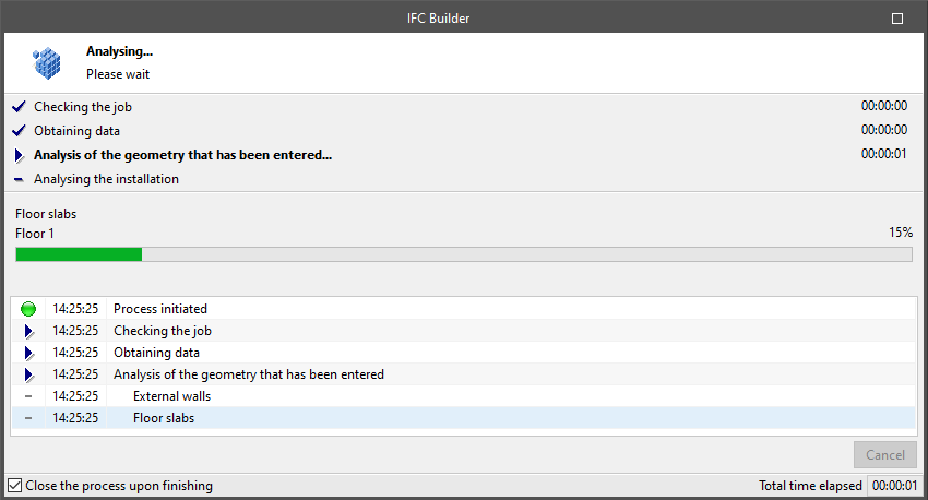
Analyse
Allows users to analyse the geometric checking of the model. The program displays a window showing the progress of the analysis.
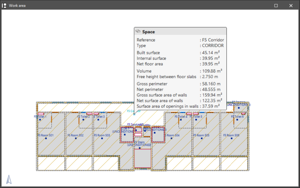
Show results
Displays the results of the last analysis carried out. Hovering the cursor over the spaces in the model displays their geometrical characteristics.
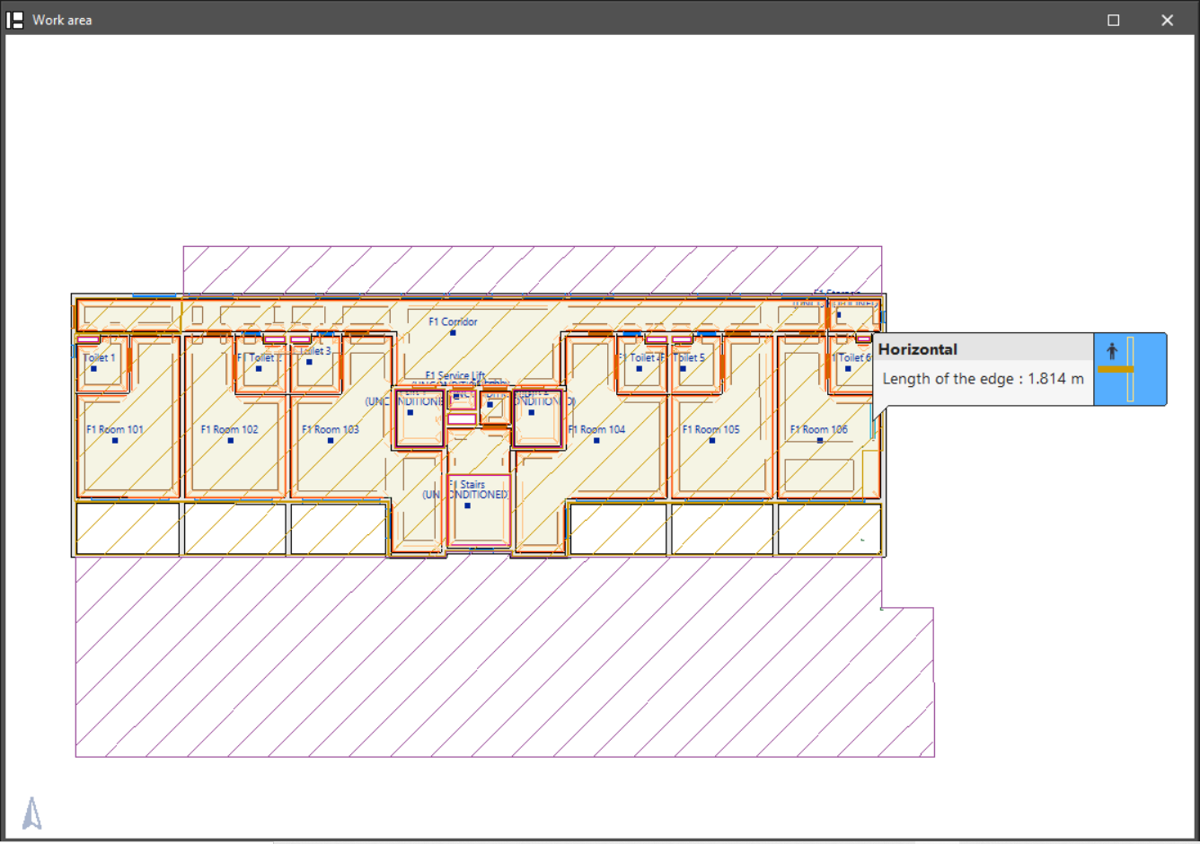
Show edges
Displays the horizontal and vertical edges generated at the intersections between elements. Positioning the cursor over each edge displays its length.
These edges can then be considered by acoustic and energy simulation programs (e.g. thermal bridges).
Show/Hide incidents
Highlights elements where an error has occurred using an on-screen warning system. The following options are available:
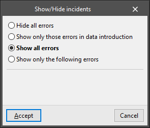
- Hide all errors
- Show only those errors in data entry
- Show all errors
- Show only the following errors
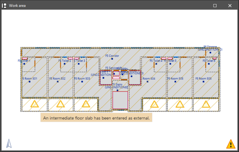
Hovering the cursor over these elements will display the message describing each error.
Results output
Directly exporting the model in IFC format
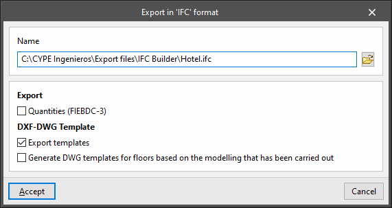
Using the "File" menu, IFC Builder allows users to export the building model directly to an IFC format file that can be saved to disk.
The program allows users to configure the following fields:
- Name
- Export
- Quantities (FIEBDC-3) (optional)
- DXF-DWG Template
- Export templates (optional)
- Generate DWG templates for floors based on the modelling that has been carried out
IFC and GLTF files supported by BIMserver.center
When exporting the project to the BIMserver.center platform, an IFC file and a 3D model in GLTF format are automatically exported for the integration of the building model in the Open BIM project, allowing it to be viewed:
- On the online platform;
- In the BIMserver.center app for iOS and Android;
- In virtual reality and augmented reality;
- In other CYPE programs.
Integration into the BIMserver.center platform
Many of CYPE's programs are connected to the BIMserver.center platform and allow collaborative work to be carried out via the exchange of files in formats based on open standards.
Please note that, to work on BIMserver.center, users can register on the platform free of charge and create a profile.
When accessing a program connected to the platform, the program connects to a project in BIMserver.center. This way, the files of the projects that have been developed collaboratively in BIMserver.center are kept up to date.

| More information: |
|---|
| For further details related to using CYPE software via the BIMserver.center platform, please click on this link. |
Options available in IFC Builder
The "BIMserver.center" group in the main toolbar contains the features needed to use IFC Builder together with other BIMserver.center tools:

The architectural models generated with IFC Builder can then be imported by a wide variety of acoustic and energy simulation and structural and MEP analysis applications linked to BIMserver.center. These apps will interpret the data needed to make the model and the analyses for each speciality, such as the number and height of floors and the geometry of the spaces, walls and partitions, floor slabs, openings or columns, depending on each case.
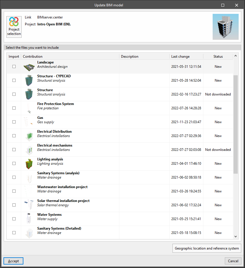
Update
Allows users to update the information contained in the models that were previously imported into the project or to import new models.
Models read from other programs and disciplines can be displayed in the 3D view of IFC Builder.
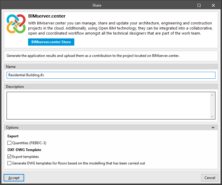
Share
Allows users to export the information of the model developed with IFC Builder to BIMserver.center to share it with other users.
During the export process, users can define information related to the identification of the files to be exported and the types of files that are generated:
- Name
- Description
- Options
- Export
- Quantities (FIEBDC-3) (optional)
- DXF-DWG Template
- Export templates (optional)
- Generate DWG templates for floors based on the modelling that has been carried out (optional)
- Export