
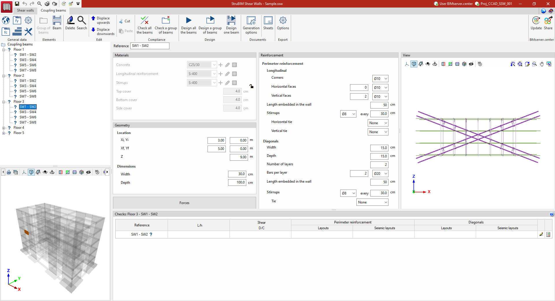
"Coupling beams" tab work area
The interface of the "Coupling beams" tab in StruBIM Shear Walls provides a work area organised into several areas:
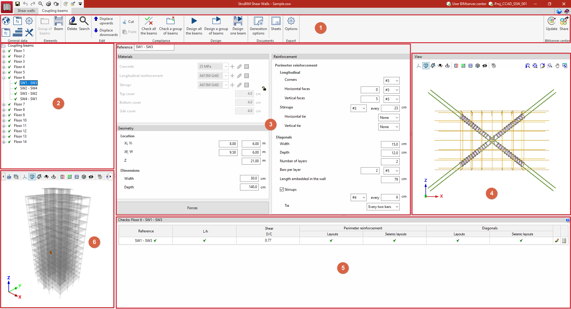
1) Top toolbar
The top toolbar contains the controls for:
- Setting the general project data
- Managing beams and groups of beams
- Editing the list of beams
- Verifying regulatory compliance
- Starting the dimensioning process, generate the drawings
- Setting the export options
- Linking the model and export the data to a project on BIMserver.center
2) Tree structure
In the left-hand side panel, the program displays a tree structure listing the coupling beams imported from the BIM model and/or defined in the file. The elements are organised into groups of beams.
3) Detailed information
To the right of the list, the program displays detailed information about the selected connecting lintel, including: the reference number, materials, geometry and reinforcement.
4) 3D view of the reinforcement
On the far right, the program displays a 3D view of the beam’s reinforcement.
5) Checklist
At the bottom of the screen, the verification table for the selected coupling beam appears. From this table, you can access detailed summaries of the check reports.
6) 3D view of the project
In the bottom-left corner, the program displays a 3D view of the entire project. The element selected in the list of beams is highlighted in this view.
Data input and output sequence for designing and analysing shear walls and tie beams
Shear walls and tie beams can be defined and analysed in the program using the following sequence of data input and output:
- Create a new project (from "File", "New").
- (Optional) Link to BIMserver.center and import shear walls and tie beams, amongst other data, based on information extracted from the BIM model. During the import process, the criteria for the arrangement of reinforcement are also checked.
On the "Shear walls" tab:
- Review general data settings (options in the "General Data" section): selection of standards, definition of materials (steel and concrete) and criteria for reinforcement layout, and configuration of anchoring, display and reporting options.
- (Optional) Enter the shear walls (from the wall list in the left-hand side panel: "Shear Walls > Add") if they have not been imported from the BIM model.
- Review the definition of each shear wall. This is carried out by following these steps:
- Select the shear wall from the list in the side panel.
- Review and/or input of "Properties", "Sections", "Segment classification" and definition of "Lateral bracing levels" (options in the "Edit" group).
- Review and/or enter the "Drifts" and "Forces" values, as well as the "Force amplification" settings for each shear wall (options in the "Edit" section).
- View and/or edit the "Reinforcement" settings (options in the central panel) if you wish to enter and check a reinforcement layout or review the layout generated by the program during the analysis process.
- Check and/or design retaining walls:
- The options in the "Compliance" section are used if the wall or all shear walls have been fully defined, and you wish to verify regulatory compliance with the reinforcement specified for them.
- The options in the "Design" group are used to allow the program to dimension the reinforcement for each wall or section, or for all shear walls if this has not been defined previously, and to carry out the regulatory compliance check.
- (Optional) Generate specific check reports for each wall (via the options in the "Checks" panel). The check editing windows allow you to edit the input data for the checks.
- (Optional) Generate and configure the sheets showing the drawings for each shear wall (via the options in the "Document" group).
On the "Connecting beams" tab:
- Review general data settings (options in the "General data" section): selection of standards, definition of materials (steel and concrete) and criteria for reinforcement layout, and configuration of beam properties and display options.
- (Optional) Enter the group of connecting beams and the connecting beams in each group (from the options in the "Elements" block) if they have not been imported from the BIM model.
- Review the definition of each coupling beam. This is carried out by following these steps:
- Select the coupling beam from the list in the side panel.
- View and/or edit the "Materials", "Geometry", "Internal forces" and "Reinforcement" for each beam (options in the central panel).
- Check and/or design connecting beams:
- The options in the "Compliance" group are used if a group of beams or all the beams in the connection have been fully defined and you wish to verify regulatory compliance with the arrangement specified for them.
- The options in the "Design" group are used to allow the program to design the reinforcement for each beam or group of beams, or for all connected beams if this has not been defined previously, and to carry out the regulatory compliance check.
- (Optional) Generate specific check reports for each beam (via the options in the "Checks" panel). The check editing windows allow you to edit the input data for the checks.
- (Optional) Generate and configure the sheets showing the drawings for each connecting beam (via the options in the "Document" group).
From any tab:
- Generate and retrieve drawings of all retaining walls and/or tie beams in the project (via "File", "Drawings").
- Generate reports of all retaining walls and/or tie beams in the project (via "File", "Reports").
- (Optional) Export to BIMserver.center (the "BIMserver.center" group, "Share").
Creating a new job, linking to a project and importing data
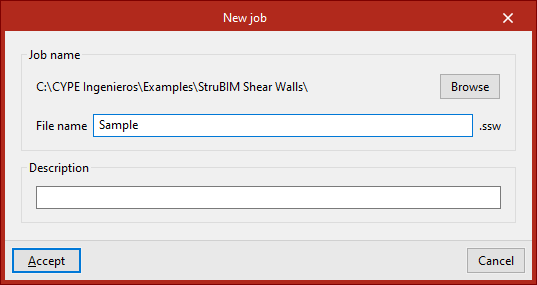
When you launch the app and click on “New”, you are given the option to create a “New project”. After entering the “File name” and “Description”, the project can then be added to an existing project on BIMserver.center.
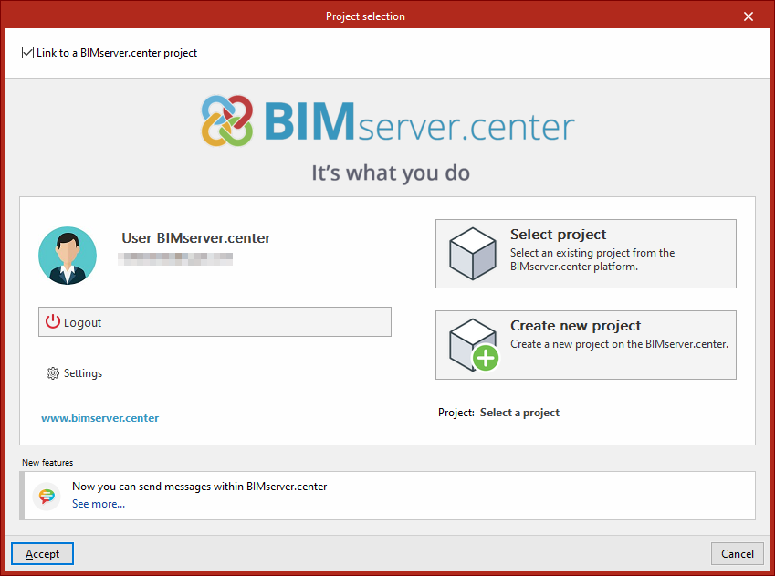
This is done in the "Project selection" window, which offers the following options:
- On the left-hand side, you can log in using a BIMserver.center account.
- On the right, use the "Select project" option to choose an existing project. You also have the option to "Create a new project". In that case, the project you create will be visible on BIMserver.center from that point onwards.
- You have the option to start the project without linking it to the BIMserver.center platform. To do this, simply uncheck the box labelled "Link to a BIMserver.center project", which is located in the top-left corner.
Once the new project has been created, you will be taken to the program’s main interface. At any point during the project, you can share or import project files via the "BIMserver.center" panel, located in the top right-hand corner of the main interface.
Importing BIM models
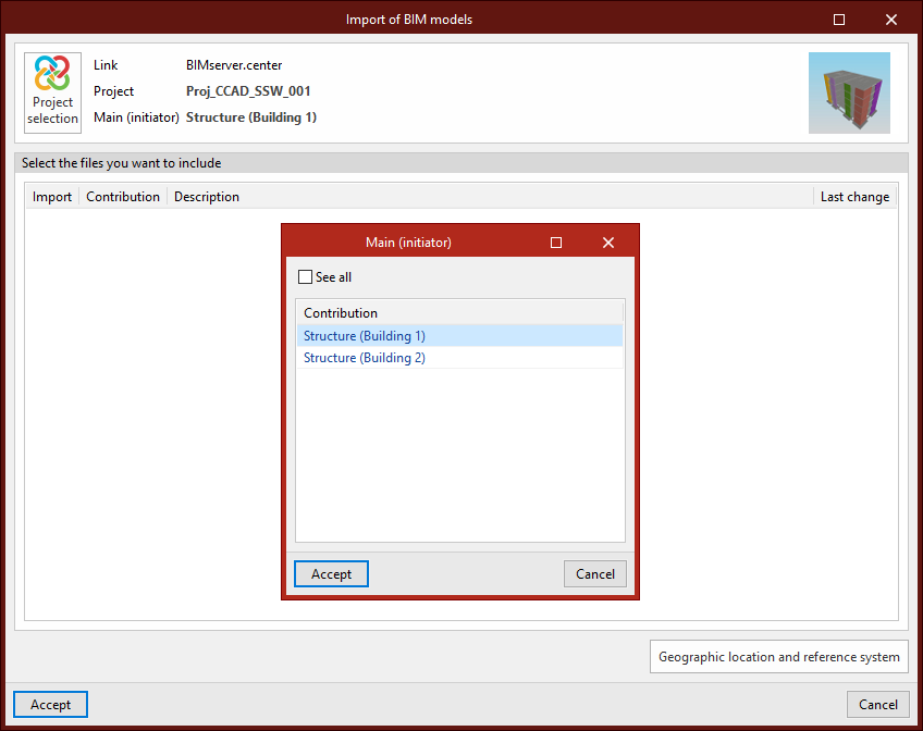
When creating a new project, if you have selected a project hosted on the BIMserver.center platform via "Select project", the "Import BIM models" window will appear, displaying the files contained in that project in IFC format.
If there are several .ifc files in the project, a pop-up window will appear in which you must select the "Main (initiator)" file from the available options. This is the file from which the information will be extracted in the data import wizard.
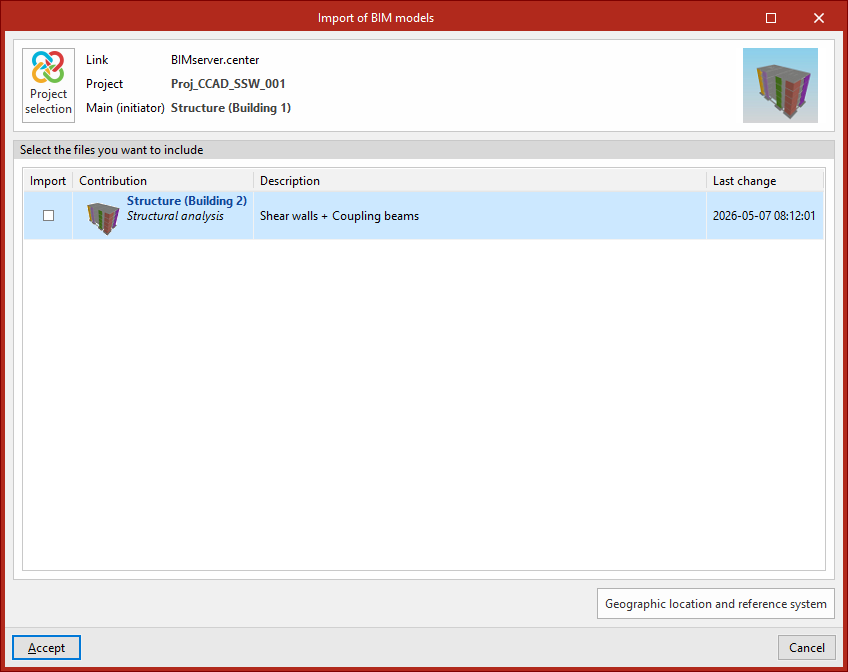
In addition, in the "Select the files you want to include" section, the app allows you to include auxiliary files for viewing within the program. To do this, tick the "Import" box and confirm.
Shear wall and coupling beam import wizard
Shear walls and coupling beams can be imported from data read from the BIM model within StruBIM Shear Walls.
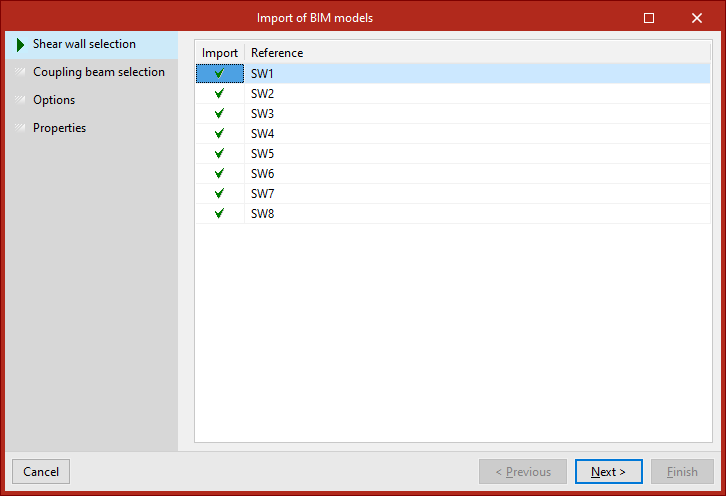
To do this, after selecting the main or starter file to be imported, the program opens a "BIM Model Import" wizard comprising the following steps:
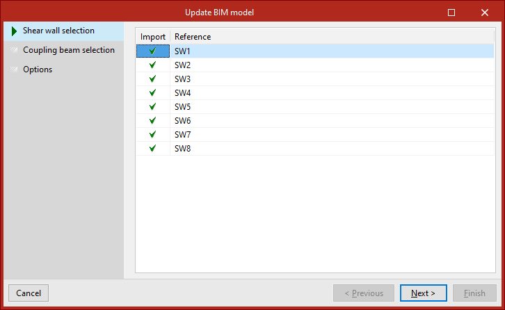
- In the first stage, you select the shear walls to be imported. Each one appears in the list with its "Reference" and can be "Imported" by ticking the box in the left-hand column.
| Note: |
|---|
| In the original CYPECAD model, you must use the "Assign shear wall function" option on the walls you have already entered so that StruBIM Shear Walls can identify them at this stage of the wizard. You can find more information about this option via this link. |
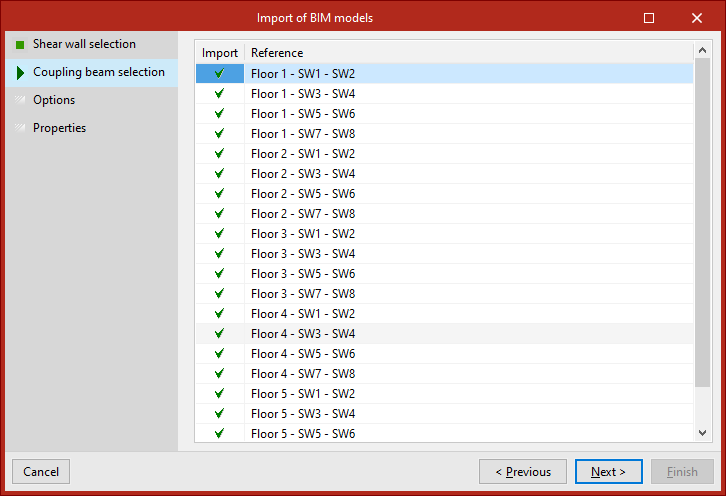
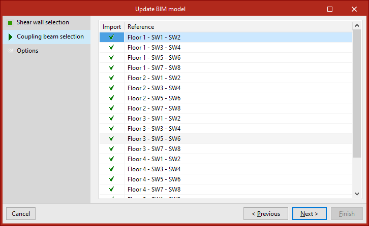
- In the second phase, you must select the "Coupling beams" you wish to import from the list provided by the program. Each beam is displayed with its “Reference” and can be “Imported” by ticking the box in the left-hand column.
| Note: |
|---|
| In the original CYPECAD model, you must use the "Automatic connection beams" and/or "Define connection beams" options on the beams you have already entered so that StruBIM Shear Walls can identify them at this stage of the wizard. You can find more information about these options via this link. |
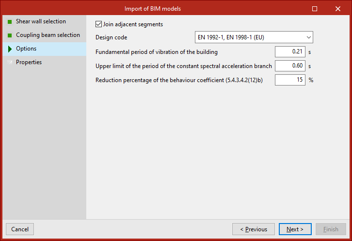
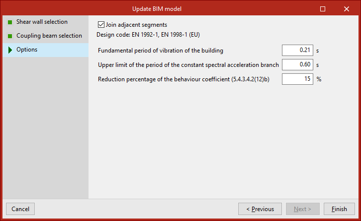
- The settings for various "Options" required for the calculation are reviewed below. You can "Join adjacent segments" by ticking the relevant box. In addition, the program identifies and allows you to select the "Design code" to be complied with from the drop-down menu and, where applicable, review and configure the parameters relating to the selected standard.
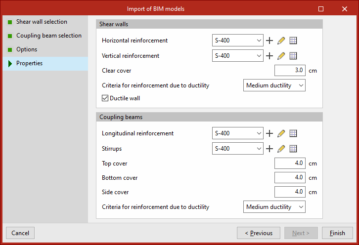
- In the final stage, the "Properties" of the imported elements are imported and checked. This includes:
- In the "Shear walls", the steel for the "Horizontal reinforcement" and the "Vertical reinforcement" is identified, as is the "Clear cover", and, depending on the selected standard, the choice of reinforcement criteria based on ductility or seismic performance.
- In the case of "Coupling beams", the steel for the "Longitudinal reinforcement" and the "Stirrups" is also identified and can be selected; the "Top cover", "Bottom cover" and "Side cover" are defined; and, depending on the selected standard, the reinforcement criteria for ductility or seismic performance are specified.
To complete the import wizard, click "Finish".
Reinforcement layout criteria
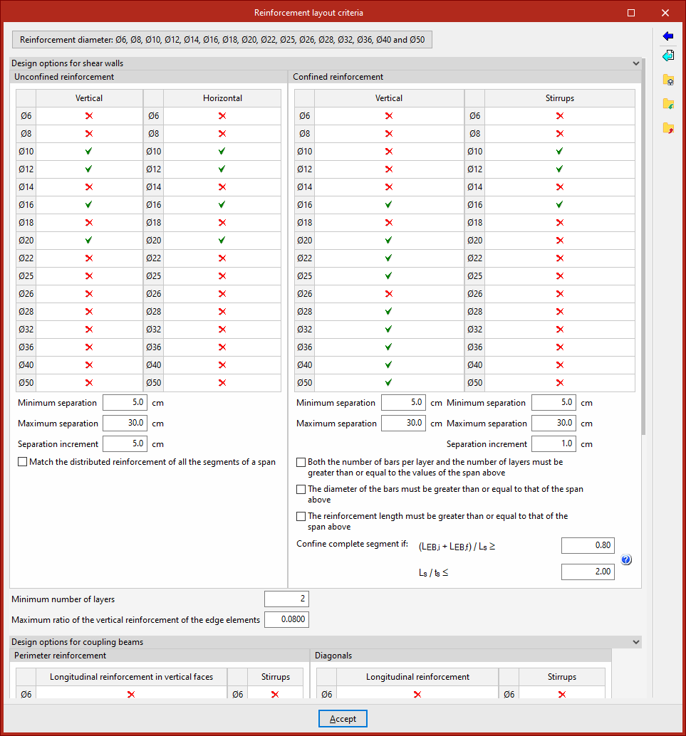
Once the import process is complete, the program will display a window allowing you to review the settings for the "Reinforcement layout criteria".
These can also be viewed later via the relevant option in the "General data" section.
Import results
Once you have clicked "Accept" in the final dialogue box and completed the import process, the program will load and open the main interface.
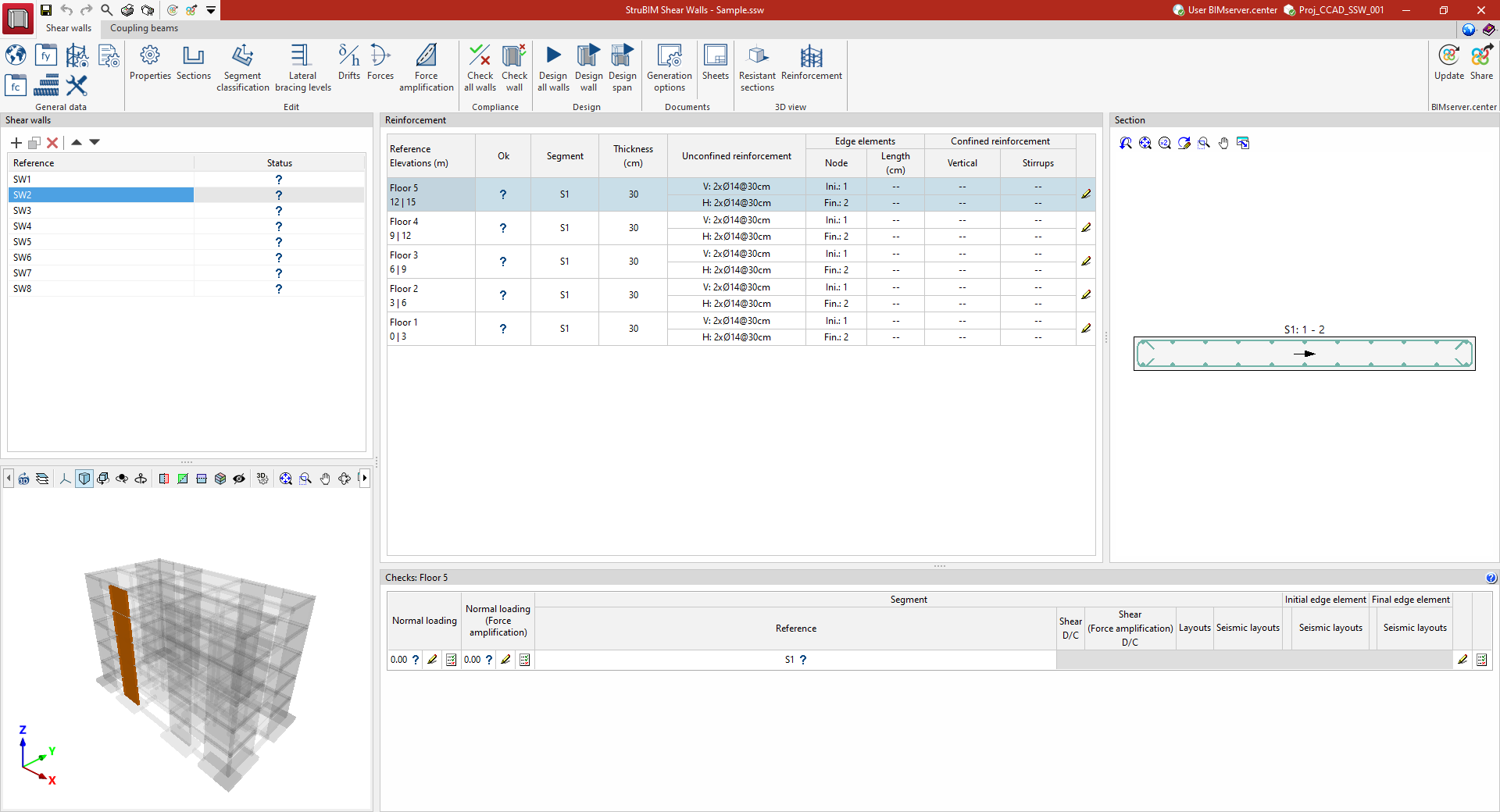
The imported shear walls and coupling beams will be displayed in the element lists on the left-hand side panel, available under the relevant tabs ("Shear walls" and "Coupling beams"). From here, you can add further elements if required.
The program will also incorporate the results of the analysis of each component, such as the forces in the shear walls and tie beams, as well as the deflections of the shear walls.
From this point onwards, users can modify the data for any of the imported walls and/or beams, as well as apply a specific reinforcement scheme and/or carry out the checks and design.
Setting the general data for the design of coupling beams
In the "General data" section of the main toolbar on the "Coupling beams" tab, you will find options for setting the following general project data:

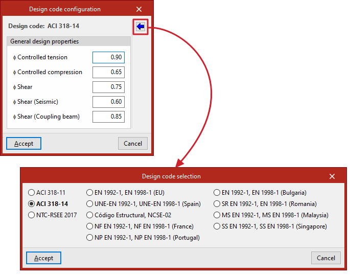
Design code configuration
This option opens a pop-up window where you can select the standard the program will use for the design. To do this, click the button on the right and select the code or combination of codes from those available in the program.
In addition, at the bottom of this window, you can adjust the values of various parameters relating to the selected code.
| Note: |
|---|
| The codes implemented in CYPE’s programs can be viewed via the following link. |
Concrete types
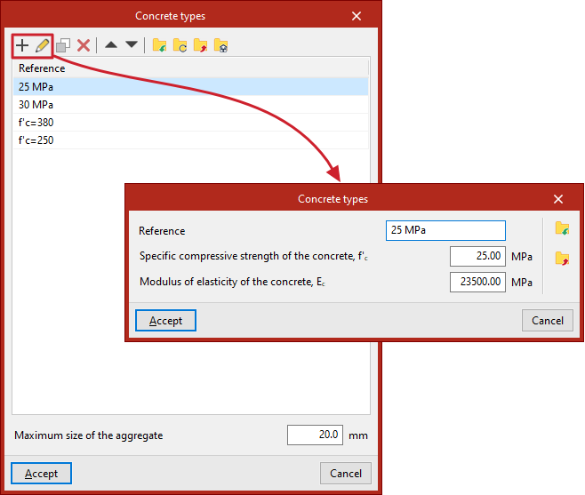
This option allows you to access the concrete type library. For each concrete type, you must define the following parameters:
- Reference
- Specific compressive strength of the concrete, fck
- Modulus of elasticity for concrete, Ec
Concrete types can be added from scratch by the user, imported and/or exported to .bibgen files saved to disk, or created using the wizard from the "Predefined" concrete types available in certain standards for each country or region. To do this, use the tools at the top of the list of types.
You can also set the "Maximum size of the aggregate" in the relevant field in this window.
Steel types
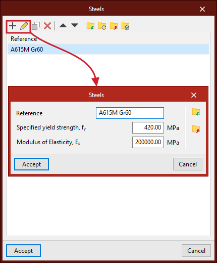
This option allows you to access the library of steel types for reinforcement. For each steel type, you must define the following parameters:
- Reference
- Specified yield strength, fyk
- Modulus of Elasticity, Es
Steel types can be added from scratch by the user, imported and/or exported to .bibgen files saved to disk, or created using the wizard from the "Predefined" steel types available in certain codes for each country or region. To do this, use the tools at the top of the list of types.
Reinforcement layout criteria
This option opens a window where you can configure the various reinforcement layout criteria for shear walls and tie beams, which the program will use in the design calculations.
Firstly, the button at the top opens a dialog box where you can add the available "Reinforcement diameters". The "Predefined bars" button, on the right, allows you to load this information based on the selected standard, region or country.
On the right-hand side, the program also offers a feature that "Restores the default installation values", as well as tools for exporting or importing the information defined in this window to .bib548 files on the hard drive.
The design options for shear walls and/or connecting beams are configured later in various drop-down sections:
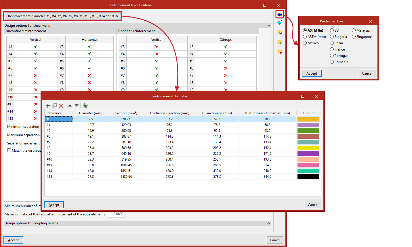
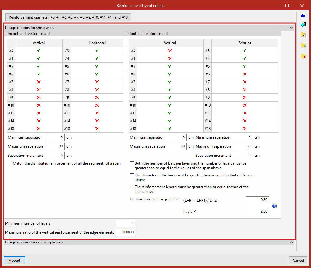
Design options for retaining walls
- Unconfined reinforcement (Vertical, Horizontal)
This table allows you to select or deselect the bar diameters or sizes that the program may or may not use in the unconfined reinforcement of shear walls. You can subsequently adjust the following parameters for this reinforcement:- Minimum spacing
- Maximum separation
- Increased spacing
- Align the distributed reinforcement of all segments in a span (optional)
- Confined reinforcement (Vertical, Stirrups)
This table allows you to select or deselect the bar diameters or designs that the program may or may not use in the confined reinforcement of shear walls. You can subsequently adjust the following parameters for this reinforcement:- Minimum spacing (vertical reinforcement)
- Maximum spacing (vertical reinforcement)
- Minimum spacing (stirrups)
- Maximum spacing (stirrups)
- Separation increment (stirrups)
- Both the number of bars per layer and the number of layers must be greater than or equal to the corresponding values for the upper section (optional)
- The diameter of the bars must be greater than or equal to that of the upper section
- The length of the reinforcement must be greater than or equal to that of the upper section
- Confine entire segment if (the parameters LEB,i, LEB,f, Ls and ts are detailed in the help diagram available on the right):
- (LEB,i + LEB,f)/Ls ≥ [value]
- Ls / ts ≤ [value]
In addition, the "Minimum number of layers" and the "Maximum ratio of the vertical reinforcement of the edge elements" are specified.
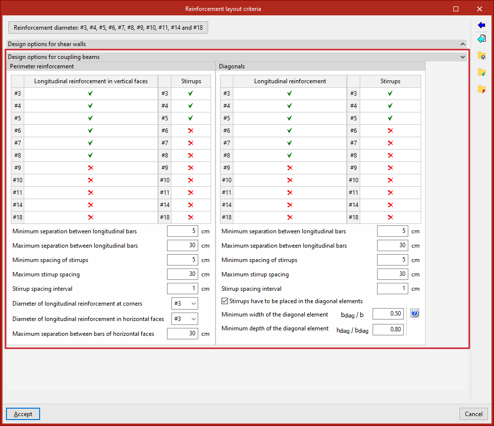
Design options for coupling beams
- Perimeter reinforcement (longitudinal reinforcement on vertical faces, stirrups)
This table allows you to select or deselect the bar diameters or designs that the program may or may not use in the perimeter reinforcement of the connecting beams. You can subsequently adjust the following parameters for this reinforcement:- Minimum spacing between longitudinal bars
- Maximum spacing between longitudinal bars
- Minimum distance between stirrups
- Maximum distance between footrests
- Spacing between stirrups
- Diameter of the longitudinal reinforcement at corners
- Diameter of the longitudinal reinforcement in horizontal sections
- Maximum spacing between horizontal face bars
- Diagonals (Longitudinal reinforcement, Stirrups)
This table allows you to select or deselect the bar diameters or sizes that the program may or may not use in the diagonal reinforcement of the coupling beams. You can subsequently adjust the following parameters for this reinforcement:- Minimum separation between longitudinal bars
- Maximum separation between longitudinal bars
- Minimum spacing of stirrups
- Maximum distance between footrests
- Spacing between stirrups
- Brackets should be fitted to the diagonal elements (optional)
- Minimum width of the diagonal member, bdiag/b
- Minimum height of the diagonal element, hdiag/bdiag
(the parameters bdiag, hdiag and b are explained in the help section on the right)
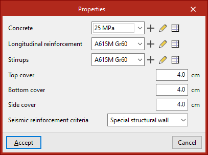
Properties
This option opens a window where you can edit the following properties for all beams:
- Concrete
In this section, you can select and/or edit one of the concrete types created in the specific library. - Longitudinal reinforcement
In this section, you can select and/or edit one of the steel types created in the specific library for use in the longitudinal reinforcement of the connecting beams. - Stirrups
In this section, you can select and/or edit one of the steel grades created in the specific library for use in the brackets of the connecting beams. - Top cover
Value of the top geometric cover of the beam assembly. - Bottom cover
Value of the lower geometric cover of the beam reinforcement. - Side cover
Value of the geometric lateral overlap of the beam assembly. - Seismic reinforcement criteria
The seismic design criteria applicable to an "Ordinary structural wall" or a "Special structural wall" may be adopted.
Display options
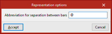
From here, you can configure the symbol for the "Abbreviation for separation between bars" (by default, '@') used when displaying the reinforcement in the drawings.
Management of coupling beams
Options in the "Elements" section
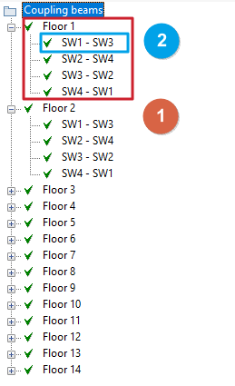
The options in the "Elements" section of the top toolbar allow you to manually add groups of beams and coupling beams to the project.

They are as follows:
- Beam group
Adds a group of beams to the list after selecting the root group ("Coupling beams"). You must enter its "Reference". - Beam
Adds a coupling beam to the list after selecting the group of beams into which you wish to insert it. You must enter its "Reference" and define its other properties in the relevant sections of the central panel of the interface ("Materials", "Geometry", "Reinforcement").
The program generates the beams and beam groups during the initial import process based on the information from the BIM model.
Defining beam groups allows you to check compliance with regulations or to design the reinforcement for groups using the relevant options.
Options in the "Edit" panel
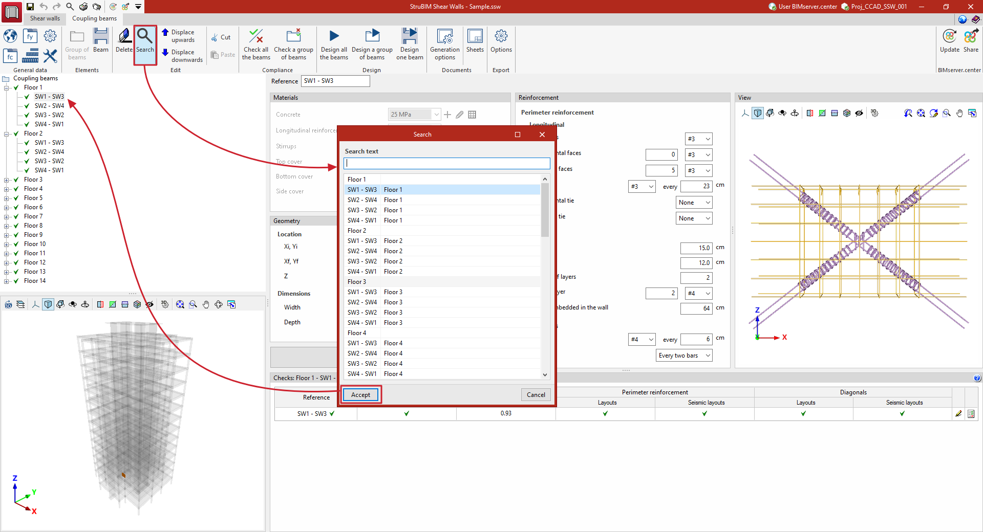
The options in the "Edit" section of the top toolbar allow you to manage the list of beams and beam groups that have been previously entered.

They are as follows:
- Delete
Removes the selected beam or group of beams from the list in the side panel. - Search
Searches for and selects a beam or group of beams by entering their reference text or part of it. - Move up
Moves the selected beam or group of beams up one position in the list. - Move down
Moves the selected beam or group of beams down one position in the list. - Cut
Cuts the selected beam or group of beams. - Paste
Pastes the selected beam or group of beams to the position selected in the list.
Defining materials, geometry and reinforcement for coupling beams
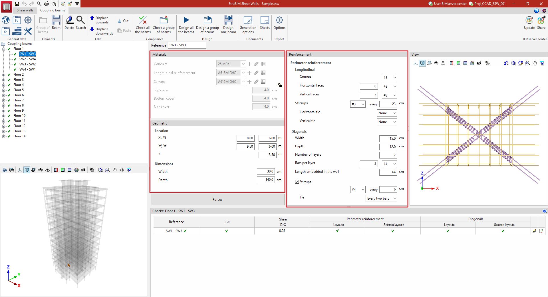
The "Materials", "Geometry" and "Reinforcement" panels, located in the centre of the interface, allow you to adjust the materials, view the geometry and edit the reinforcement layout for the coupling beams selected from the list on the left-hand side.
Materials
This panel shows the "Concrete" used in the selected coupling beams, the steel used in the "Longitudinal reinforcement" and the "Stirrups". It also indicates the "Top cover", the "Bottom cover" and the "Side cover" of the reinforcement bars arranged in the beam.
By default, the program retrieves this information from the settings defined under the "Properties" option in the "General data" section, which applies to all beams in the project.
In any case, you can click on the "Lock/unlock the values of material" option, located to the right of this section, to unlink these values from the general settings and edit them individually for each beam.
Geometry
This panel allows you to modify the geometry of the selected coupling beam and displays the following information:
- Position
Global plan coordinates of the start point ("Xi", "Yi") and the end point ("Xf", "Yf") of the coupling beams, as well as its global "Z" coordinate. - Dimensions
Width and depth of the coupling beam.
The program retrieves this data during the initial import process from the information in the BIM model.
Reinforcement
- Perimeter reinforcement
Definition of the perimeter reinforcement for the tie beam, comprising:- Longitudinal
The longitudinal reinforcement includes the four "Corner" bars, for which the diameter is selected, and the additional bars on the "Horizontal faces" and "Vertical faces", for which the number of additional bars per face is entered and the diameter is selected. - Stirrups
The diameter and spacing of the stirrups are defined. The “Horizontal tie” and “Vertical tie” patterns for the longitudinal reinforcement bars are also specified, either as “All tied” or “None”.
- Longitudinal
- Diagonals
The reinforcement diagonals for the coupling beam are defined. To do this, specify the "Width", "Thickness", "Number of layers", and the number of "Bars per layer", as well as their diameter.
In addition, enter the "Length embedded in the wall" adjacent to the coupling beam.
Finally, tick the "Stirrups" box if the diagonal has them, selecting their diameter and spacing, as well as the "Tie" pattern for the diagonal bars ("All tied", "Every two bars" or "None").
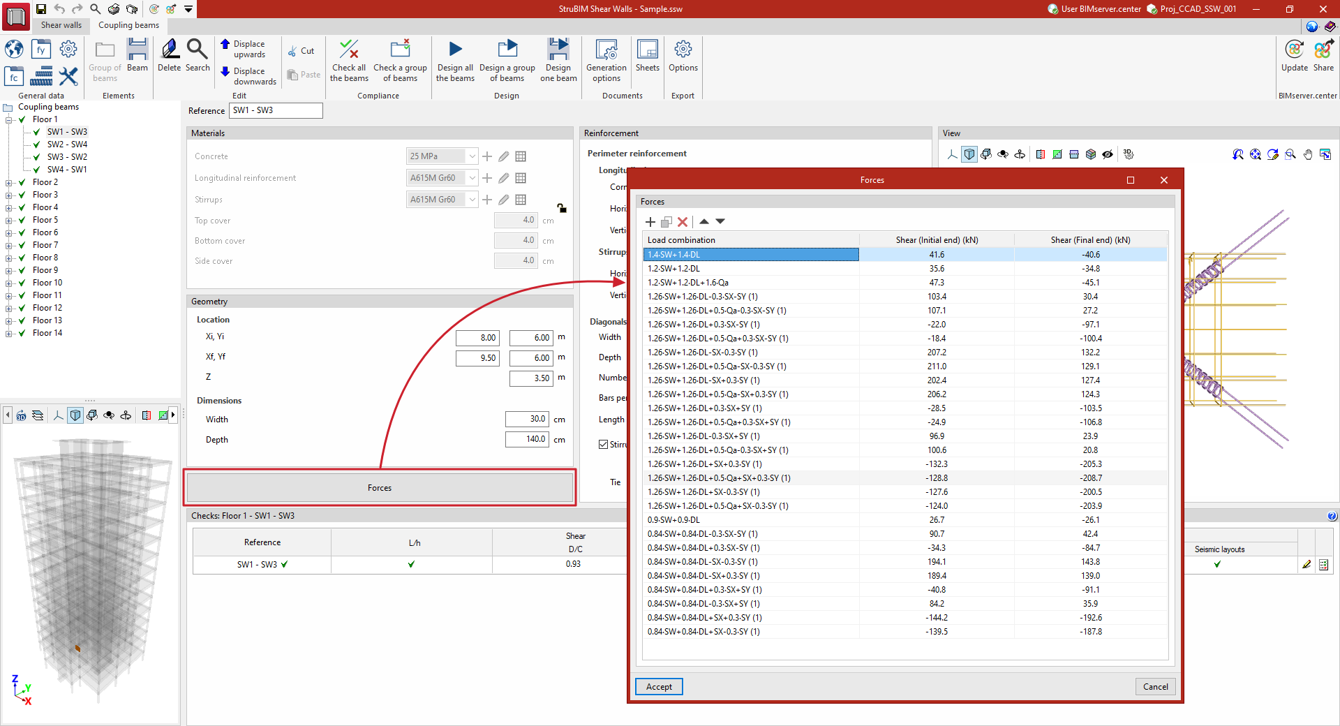
Forces in coupling beams
The "Forces" button, located in the centre of the interface, allows you to view and/or modify the forces in the beam selected from the list on the left-hand side.
Clicking on it opens a pop-up window displaying a table of the forces acting on the beam. Each force is determined by the following data:
- Combination
The reference to the combination of loadcases under which the applied forces occur. - Shear (Initial end)
Shear force value at the initial end of the coupling beam. - Shear (Final end)
Shear force at the end of the coupling beam.
The program retrieves this data during the initial import process from the analysis results included in the BIM model.
Checks on coupling beams
The "Checks" panel, located at the bottom of the interface, displays a table of checks for the coupling beam selected in the side panel.
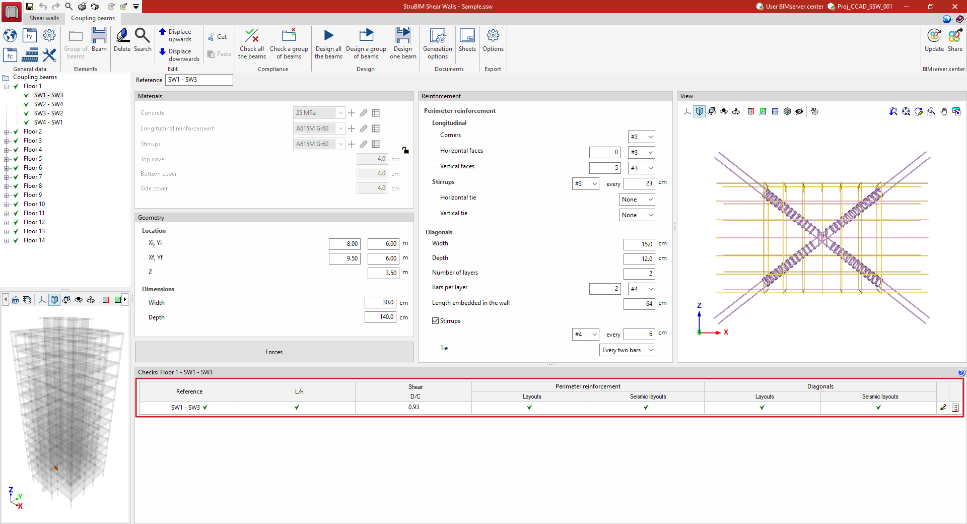
The table contains the following columns:
- Reference
Reference number of the coupling beam. - L/h
Compliance status of the beam's L/h aspect ratio. - Shear D/C
The demand capacity ratio of the beam's shear force to its shear capacity. - Perimeter reinforcement
Status of compliance of the beam’s perimeter reinforcement with the regulatory “Layouts” and with the regulatory "Seismic layouts”. - Diagonals
Compliance status of the beam’s diagonal bracing with the regulatory “Layouts” and with the regulatory “Seismic layouts”. - Edit
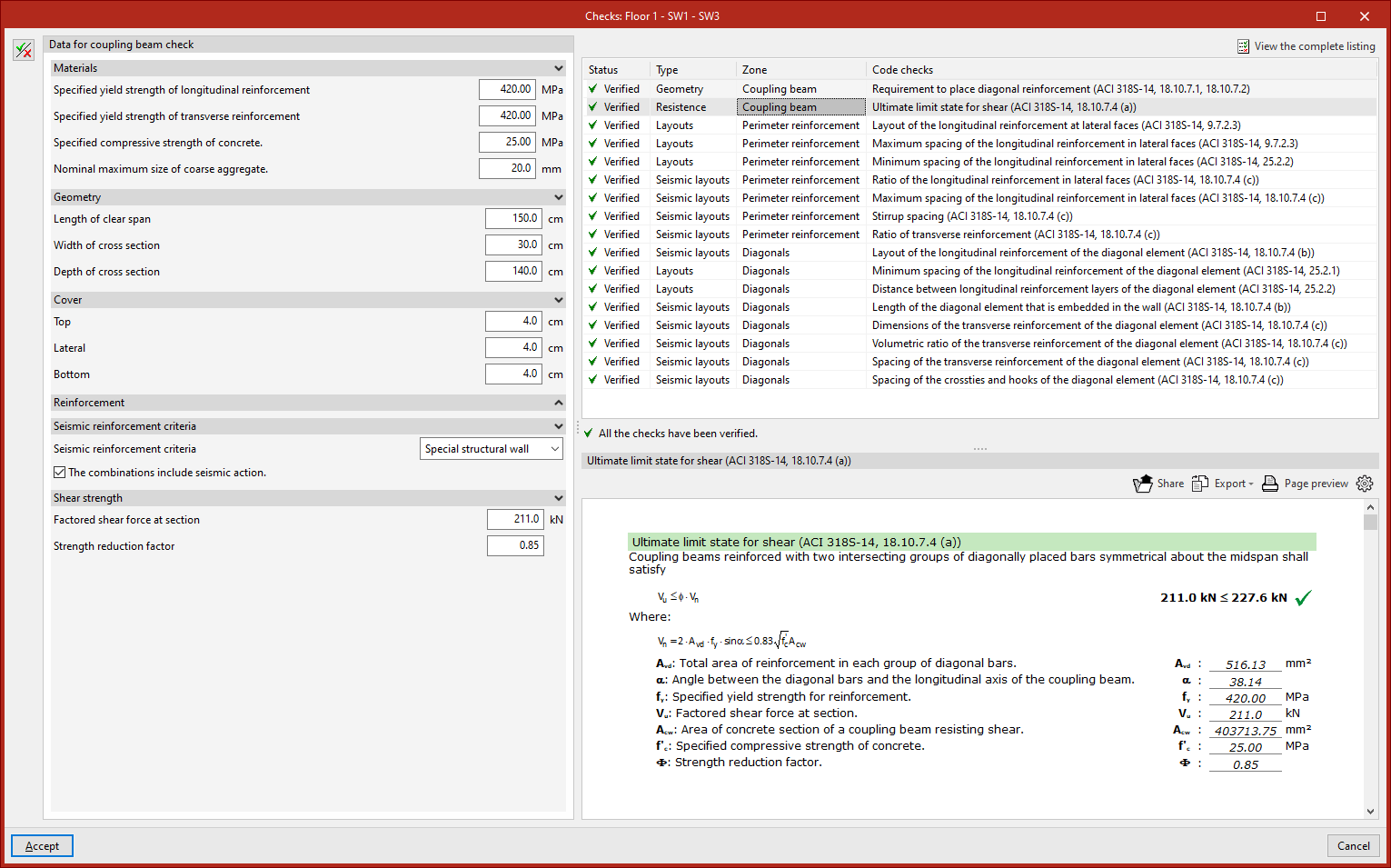
Selecting this option opens a pop-up window where you can do the following:- At the top, a list is shown of each of the regulatory "Checks" carried out on the coupling beam, indicating its compliance "Status", the "Type" of check, the "Zone" where it is carried out, and a summary of the "Check".
- The lower section displays the details of the check selected in the upper section, including a reference to the applicable regulatory section, the terms and data used, and the analyses performed by the program.
- On the left, using the "Show editing panel" option, you can edit the "Data for checking the coupling beam", including details of materials, geometry and cover, reinforcement arrangements, the seismic reinforcement criteria to be considered, and the design shear force.
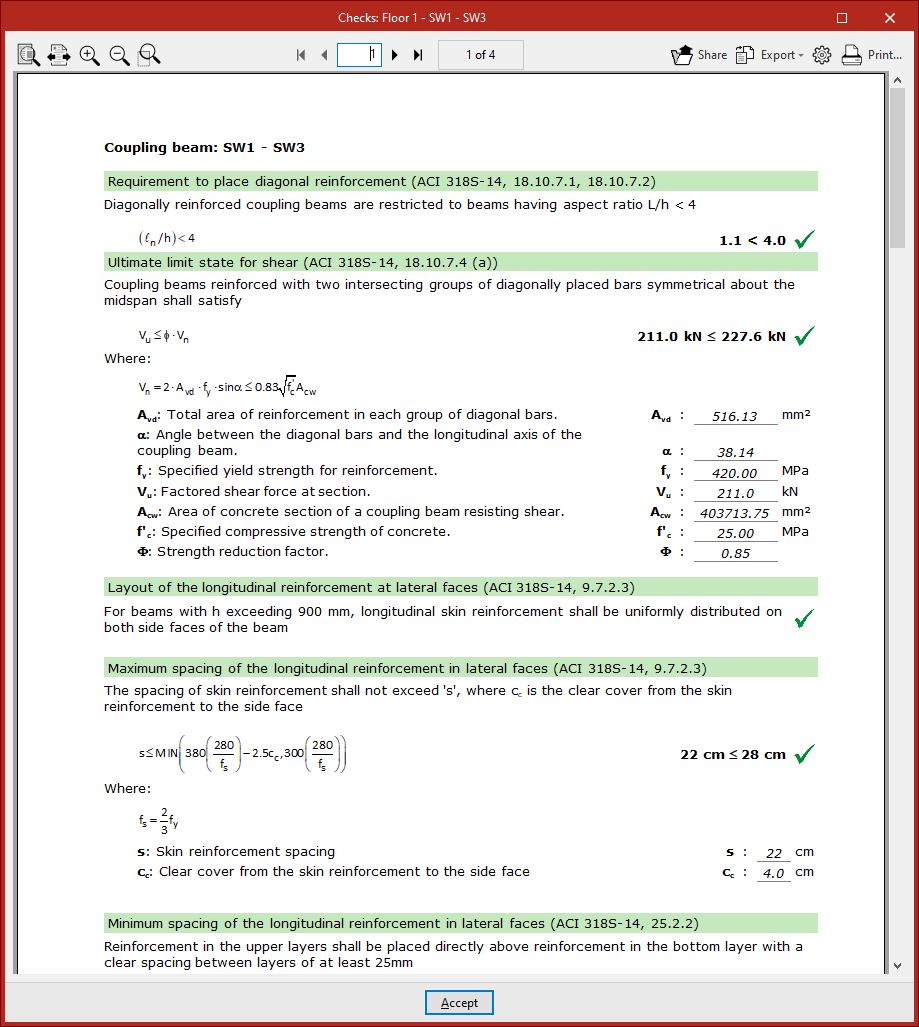
- Report
This option allows you to access the list of detailed checks for the coupling beam. This report can be printed directly or exported in various formats.
Compliance with coupling beams
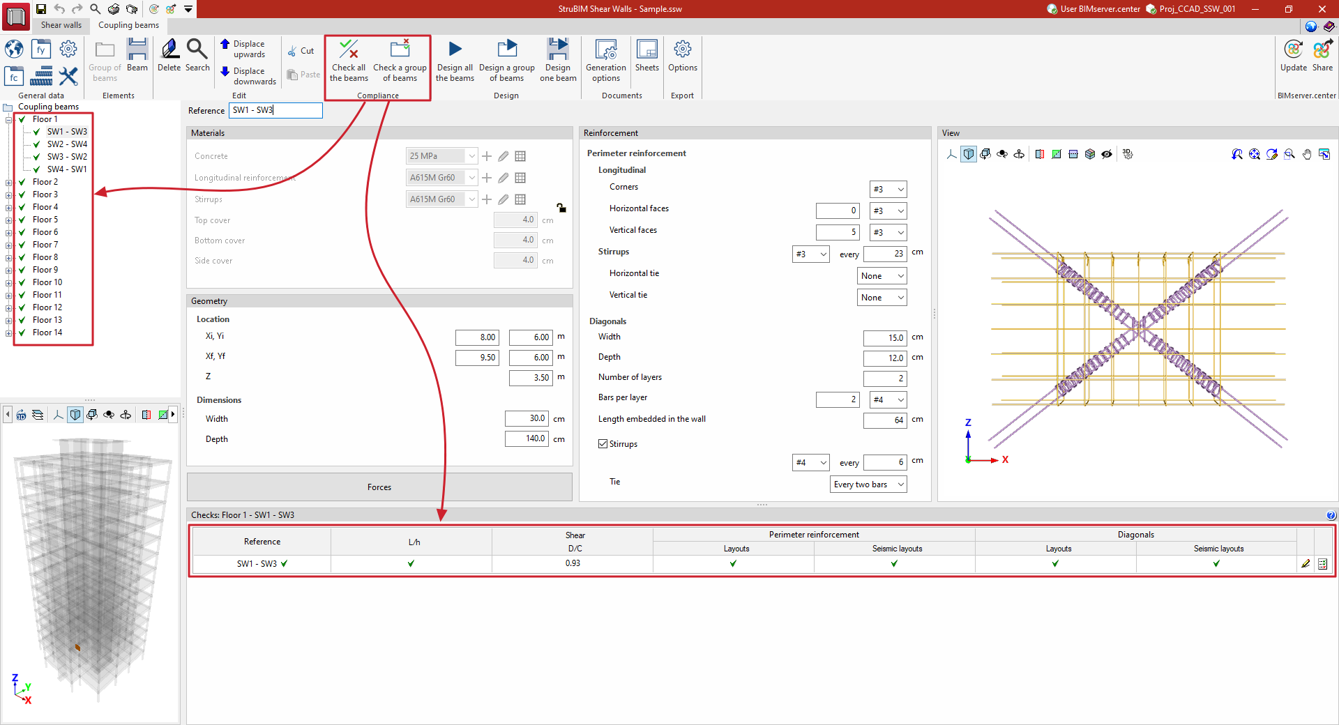
In the "Compliance" section of the main toolbar on the "Coupling beams" tab, you will find options that allow you to check that the defined coupling beams comply with regulations:

Check all the beams
This option allows you to check all the connecting beams on site.
Check a group of beams
This option allows you to check the group of beams currently selected in the list.
| Note: |
|---|
| Once the check has been completed, the program updates the information displayed in the “Coupling Beams” list on the left-hand panel and in the checks table at the bottom of the interface. Status indicators in both locations show whether a check has not yet been performed, has been completed successfully, or has been completed with non-compliant results. |
Designing coupling beams
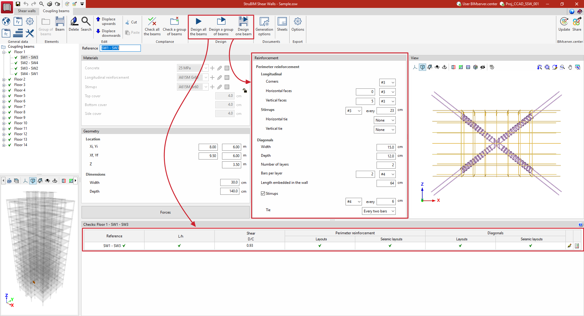
In the "Design" section of the main toolbar on the "Coupling beams" tab, you will find the options that allow you to dimension the defined coupling beams:

Design all the beams
This option allows you to check and design all the connecting beams in the project.
Design a group of beams
This option allows you to check and design all the beams in the group currently selected in the list.
Design a beam
This option allows you to check and design the selected coupling beam.
Drawings of coupling beams
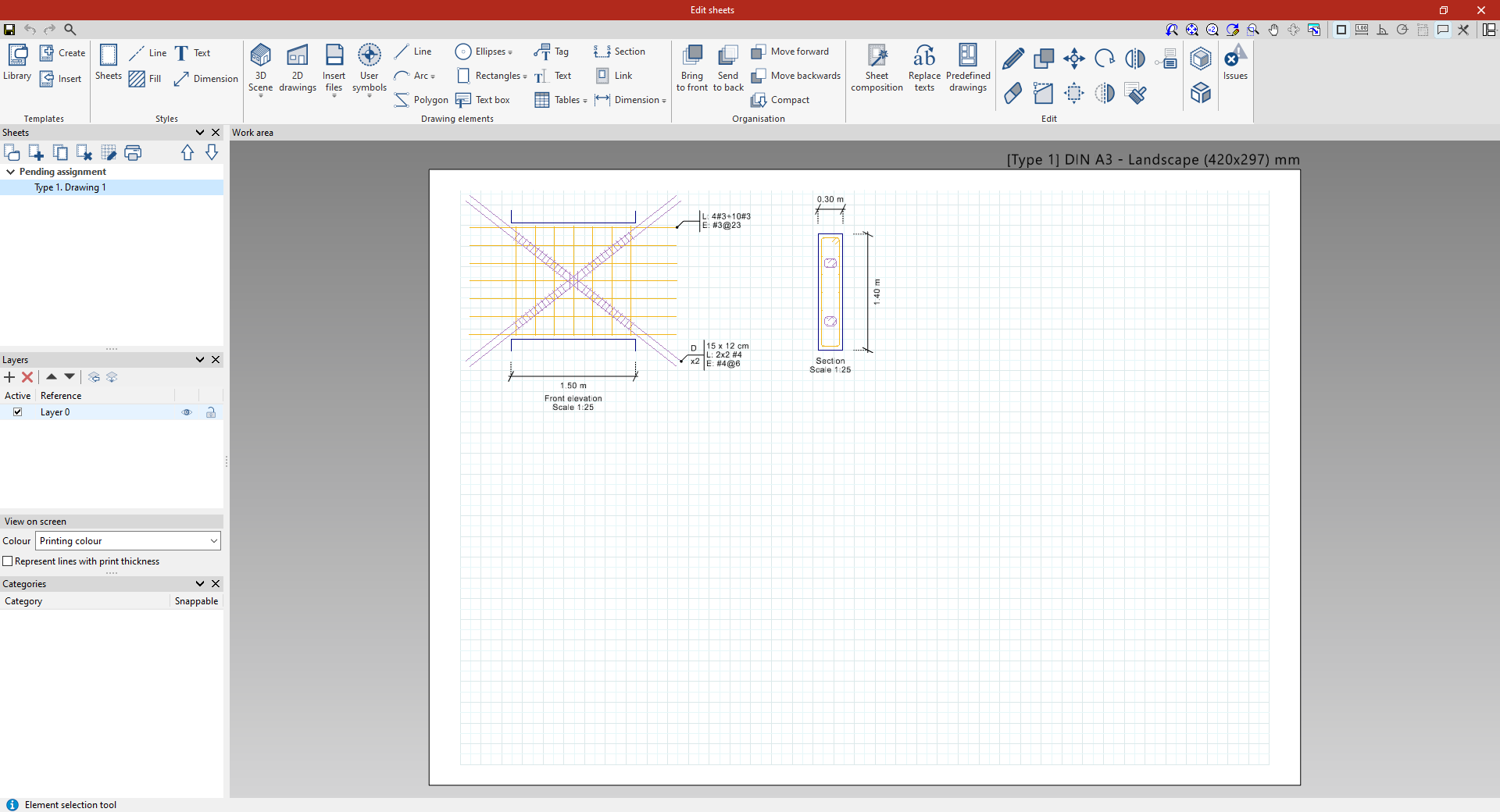
StruBIM Shear Walls includes tools that allow for the automatic or manual generation of drawings for the coupling beams designed within the program. These drawings include elevations and cross-sections of the beams, which facilitate the graphical documentation of the designs produced.
The types of drawings generated are:
- Elevation
View of the connecting beams. - Section
View of the section of the coupling beam.
The perimeter reinforcement of the beam and the diagonal stiffeners are marked.
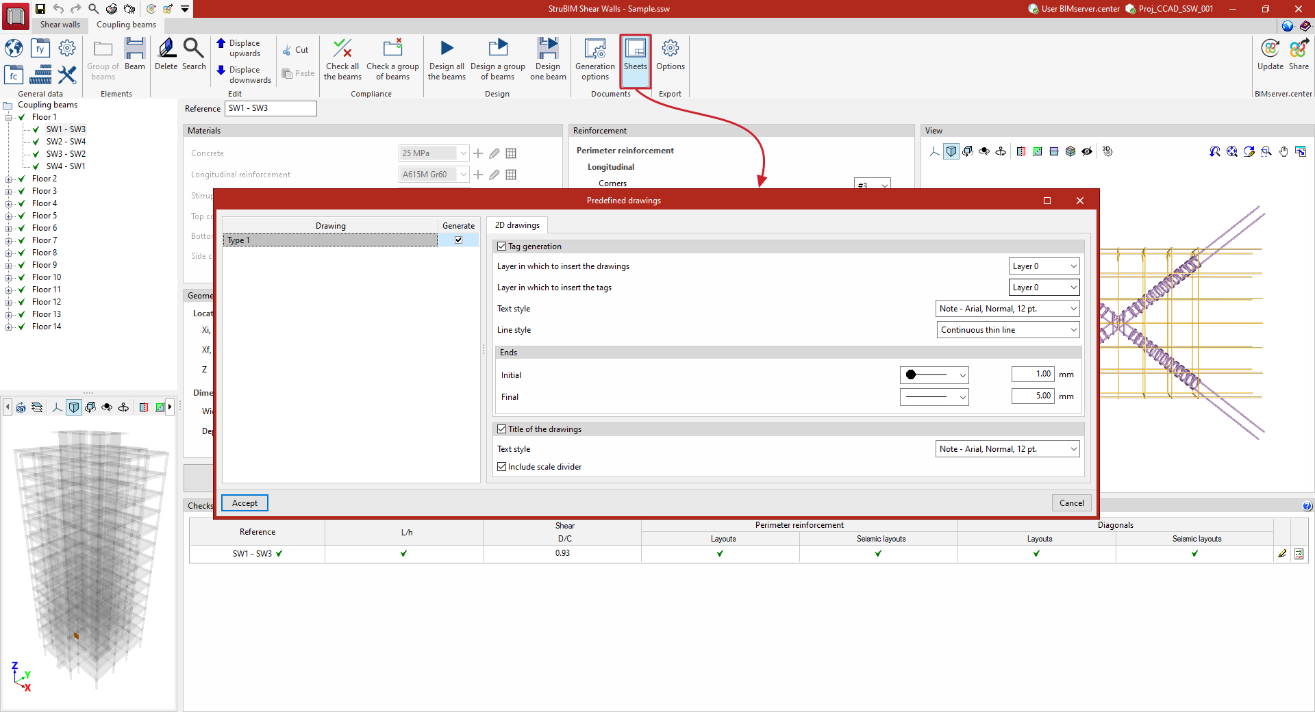
Access to the slide editor
Clicking on the "Sections" icon within the "Documentation" section opens the section editor for the selected beam.
The first time you access this section, the program will ask if you wish to automatically generate the predefined sheet layout. The layout of each sheet will depend on the settings previously selected under "Generation options".
You can rearrange the content using the "Move" option in the "Edit" panel, and insert other drawings from "2D Drawings" in the same panel.
Setting the display of sheets
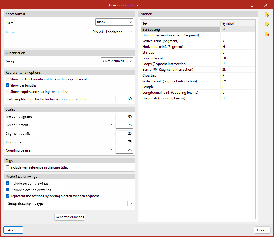
In the "Generation options" dialogue box, which includes tools for generating both beam-to-beam connection plates and shear walls, you can define:
- Slide format
Defines the format of the sheets generated:- Using the "Type" option, you can select a template so that the sheet adopts the format associated with it.
- The "Clear" option allows you to manually set the sheet format.
- Organisation
Specifies the slide group into which the generated slides will be inserted. - Display options
This section contains the following options:- Show the total number of bars in the edge elements
When enabled, the reinforcement labels for edge elements show the total number of vertical bars (e.g. 14 #10). If disabled, the number of layers and the number of bars per layer are shown (e.g. 2x7 #7). - Show bar lengths
Adds the bar lengths to the labels on the horizontal bars. - Show lengths and spacings with units
- Scale amplification factor for bar section representation
- Show the total number of bars in the edge elements
- Scales
- Scale divider for drawing:
- Section diagrams
- Section details
- Segment details
- Elevations
- Coupling beams
- Tags
- Include the wall reference in the title of the drawings.
- Include the wall reference in the title of the drawings.
- Predefined drawings
- Specify whether the predefined wall sheets should:
- Include section drawings
- Include elevation drawings
- Represent the sections by adding a detail for each segment
Choice between two display modes. If this option is disabled, the entire section is shown with all its reinforcements. If enabled, a general outline of the section is displayed along with specific details for each segment. - Drawings can be displayed as one per sheet or grouped by type.
- Symbols
Defines the symbols or abbreviations used in the text, notes and explanations that appear on the labels.
Generating predefined sheets
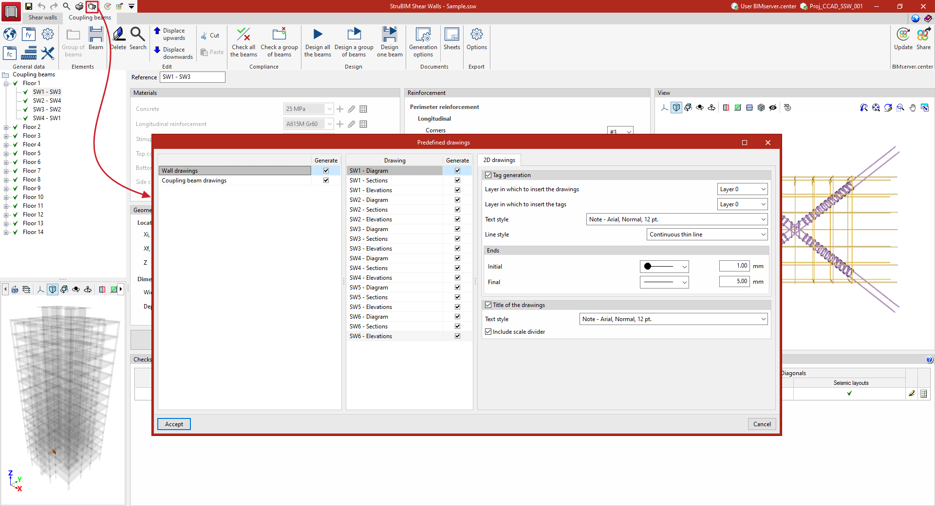
The sheets for each element can be generated automatically either when you first access the "Slides" section or, within that section, via the "Predefined slides" option.
It is also possible to generate drawings of all shear walls and all connecting beams in the project using the "Drawings" option in the "File" menu or at the top of the main interface.
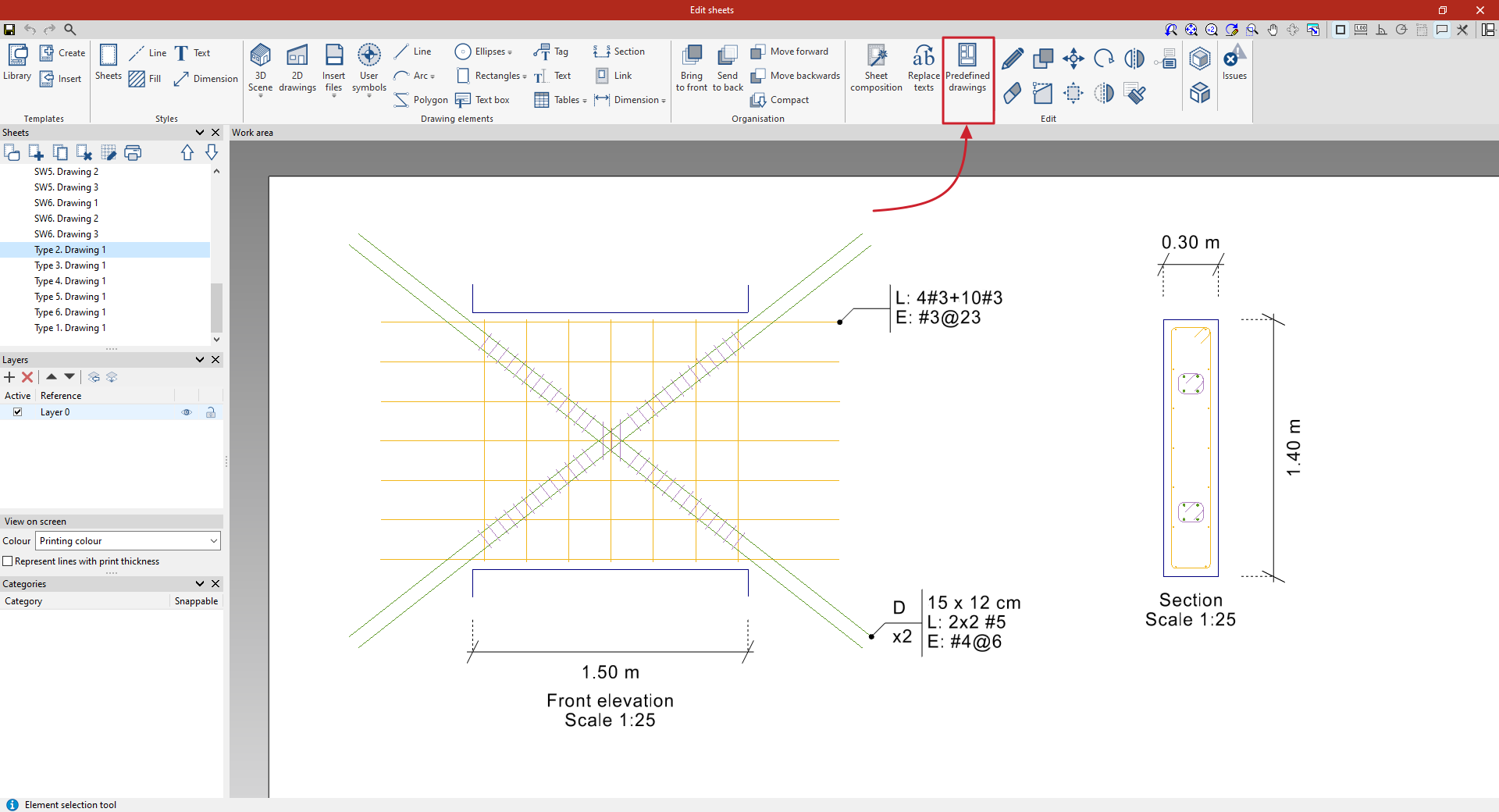
When these options are used, depending on the settings specified under "Generation options", the program generates the section and elevation drawings, together with the reinforcement labels.
The elevation drawings show the length of the beam and depict and label the longitudinal reinforcement and diagonal bracing, including corner bracing, additional bracing on the faces of the beams, the stirrups for the longitudinal reinforcement, and the bars forming the diagonal bracing and their stirrups.
The sections show the depth and width of the beam, and illustrate the longitudinal reinforcement and its stirrups, as well as the reinforcement for the two diagonal braces.
| Further information: |
|---|
| The user interface of the sheet editor is similar to the one in CYPE Connect; detailed information on this is available via the following link. This sheet editor is also integrated into other programs, such as StruBIM Steel and CYPE Architecture. |
Integration into the BIMserver.center platform
Many of CYPE's programs are connected to the BIMserver.center platform and allow collaborative work to be carried out via the exchange of files in formats based on open standards.
Please note that, to work on BIMserver.center, users can register on the platform free of charge and create a profile.
When accessing a program connected to the platform, the program connects to a project in BIMserver.center. This way, the files of the projects that have been developed collaboratively in BIMserver.center are kept up to date.

| More information: |
|---|
| For further details related to using CYPE software via the BIMserver.center platform, please click on this link. |
Options available in StruBIM Shear Walls
The “BIMserver.center” section of the main toolbar, available in both the “Shear walls” and “Coupling beams” tabs, contains the features required to use the program in conjunction with other BIMserver.center tools.


Updating
Update the information contained in the "Main (Initiator)" file template previously imported into the project, and import any additional templates if required.
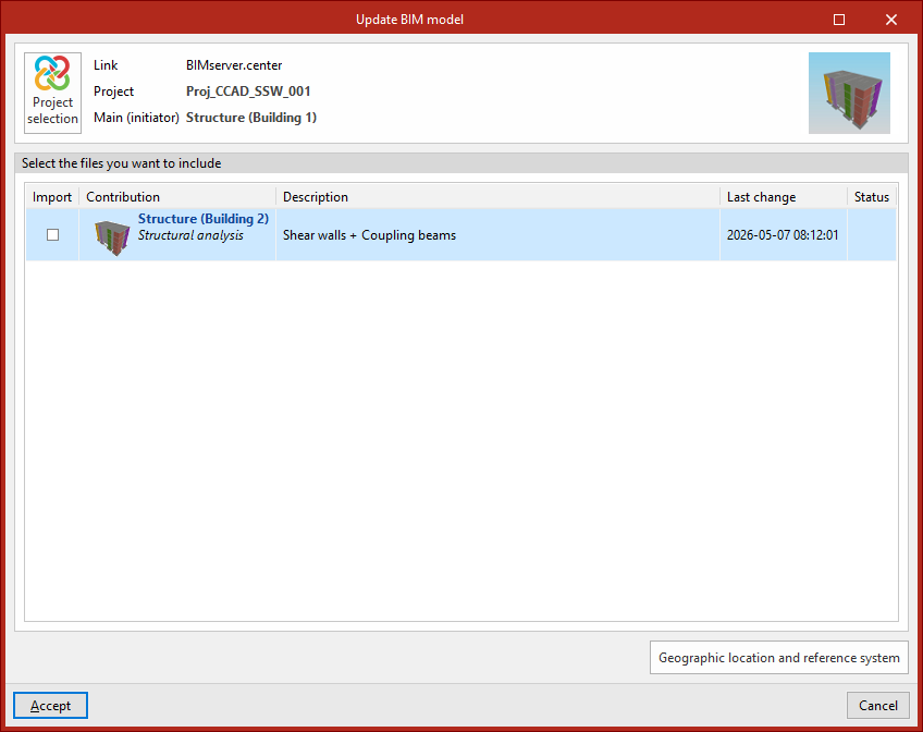
The update process launches an import wizard for shear walls and connecting beams, similar to the one that appears when creating a new project, allowing you to carry out the "Shear wall selection", the "Connecting beam selection" and the "Options" configuration.
Sharing
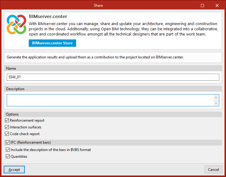
Exports the installation data generated by the program to BIMserver.center so that you can share it with other users.
During the export process, you can specify the details of the .ifc file to be exported and select any additional files you wish to share:
- Name
- Description
- Options
In this section, you can include the following documents and information in the export:- Reinforcement report (optional)
- Interaction surfaces (optional)
- Code check (optional)
- IFC (Reinforcement bars) (optional)
If this option is enabled, a file in IFC format containing information about the model’s reinforcement can be generated. The following options can be configured:- Include the description of the bars in BVBS format (optional)
In the .ifc file, an additional parameter is added to each bar containing its description in BVBS format, which provides the necessary information on the shape of each member for manufacturing purposes. - Quantities (optional)
Selecting this option includes information about the quantities in the template in the export file.
- Include the description of the bars in BVBS format (optional)
| Note: |
|---|
| Certain export settings for the reinforcement of tie beams can be adjusted using the "Options" in the "Export" section of the top bar, such as selecting the "Stirrup type" for the perimeter reinforcement ("Open" or "Closed") or the "Length embedded in the wall" for the diagonal reinforcement, as appropriate. |
