Update history​​
CYPE 3D
Buckling analysis in shells
- Published on
- 2024.e
Exporting and importing rotational stiffnesses
Version 2024.e implements the export of the rotational stiffnesses of the connections in CYPE Connect and StruBIM Steel. The import of rotational stiffnesses is also implemented in CYPE 3D.
This improvement allows the rotational stiffness of connections analysed in CYPE Connect or StruBIM Steel to be considered in the original CYPE 3D structure.
- Published on
- 2024.e
Optional consideration of bar eccentricities in the analysis
Up until version 2024.e, the eccentricities defined in bars from "Bar > Describe disposition" always affected the design model.
As of version 2024.e, users can now choose whether or not to take eccentricities into account in the analysis.
When the option is not activated in a bar, this bar is considered to be centred in the design model.
- Published on
- 2024.e
Shortcuts for all applications
CYPE apps have keyboard shortcuts common to all programs. In versions before 2024.e, each program displayed the keyboard shortcuts for each app via the "Search and activation of commands and options" in the top left-hand corner of the programs.
As of version 2024.e, the "Shortcuts for all applications" tab has been implemented in the dialogue box displayed when selecting this option and it shows all the keyboard shortcuts common to CYPE apps.
- AcouBAT by CYPE, Arquimedes, CYPE 3D, CYPE Architecture, CYPE Connect, CYPE Connect Classic, CYPE Construction Systems, CYPE Cost Estimator, CYPE Gas Supply, CYPE Sewerage, CYPE Water Supply, CYPECAD, CYPEFIRE, CYPEFIRE FDS, CYPEFIRE Hydraulic Systems, CYPEFIRE Pressure Systems, CYPEHVAC, CYPEHVAC Radiant Floor, CYPEHVAC Schematics, CYPELEC, CYPELEC Distribution, CYPELEC Electrical Mechanisms, CYPELEC MULTILINE, CYPELEC Networks, CYPELEC PV Systems, CYPELUX, CYPEPLUMBING, CYPESOUND, CYPETEL Wireless, CYPETHERM BRIDGES, CYPETHERM EPlus, CYPETHERM HYGRO, CYPETHERM LOADS, CYPEURBAN, IFC Builder, Open BIM Analytical Model, Open BIM Cable Routing, Open BIM Layout, Open BIM Model Checker, Open BIM Quantities, Open BIM Site, Open BIM Switchboard, Portal frame generator, StruBIM Box Culverts, StruBIM Cantilever Walls, StruBIM Deep Beams, StruBIM Embedded Walls, StruBIM Shear Walls, StruBIM Steel
- Published on
- 2024.e
Shells with orthotropic material. Assistant for entering CLT panel properties
In version 2024.c, the possibility of defining orthotropic materials for designing shells was added to CYPE 3D. As of version 2024.d, a tool is included to make it easier to enter the data specified by a CLT panel manufacturer in their European Technical Assessment document.

- Published on
- 2024.d
Fixity at bar ends
Up until version 2024.d, CYPE 3D allowed users to edit the fixity at bar ends in the XY and XZ planes.
As of version 2024.d, the degree of fixity in the YZ plane can also be edited. Each end can be assigned a fixity coefficient (0 for the hinged end; 1 for the fixed end) or a rotational stiffness can be assigned.
- Published on
- 2024.d
Buckling analysis (global stability) (new module)
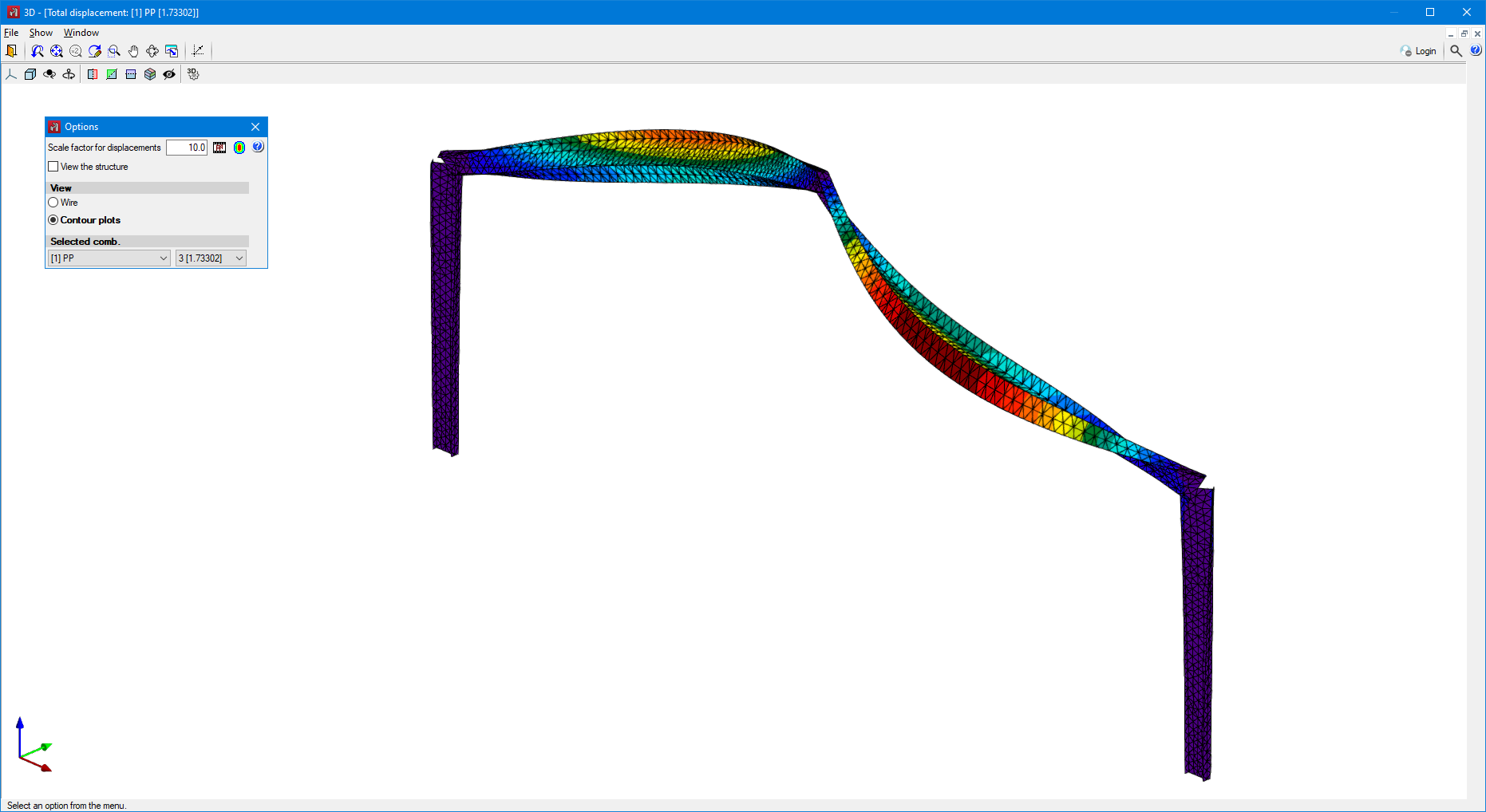
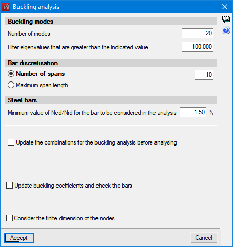
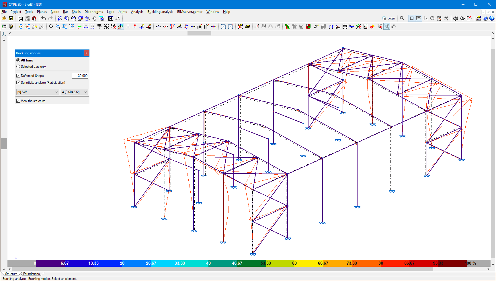
As of version 2024.d, users can carry out the linear buckling analysis. The linear buckling analysis allows the critical load factors and the buckling deformations of the structure to be determined for each analysed combination by solving an eigenvalue problem.
In order to carry out this analysis, the user's license must have the necessary permission for this module and for the "OpenSees analysis engine".
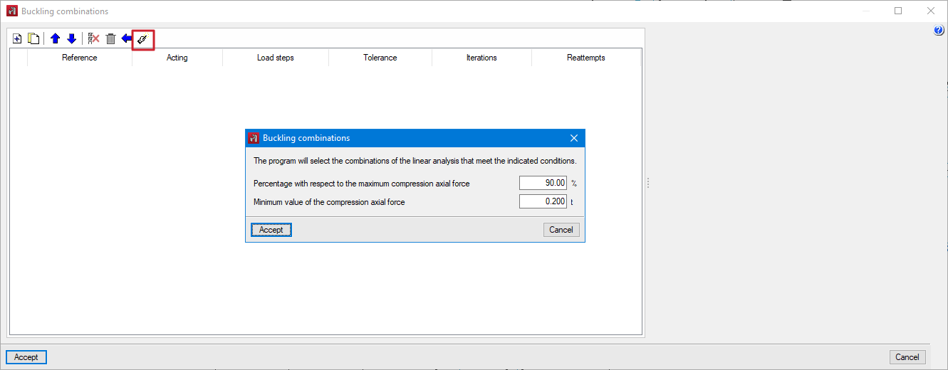
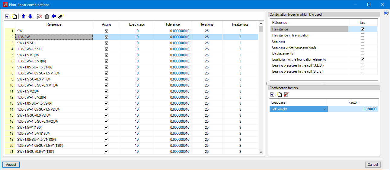
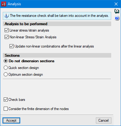
Before solving this problem, a static analysis of the defined combinations is carried out. The result of this analysis allows users to determine both the axial compression forces of each bar and the behaviour of the non-linear elements for each combination.
Once the buckling analysis has been carried out, a participation analysis is performed to determine the influence of a buckling mode on the bars in the structure. To obtain it, a participation percentage of 100% is assigned to the bar that absorbs the greatest deformation energy in that mode and, for the rest of the bars, it is calculated as the quotient between their deformation energy and that of the previously mentioned bar.
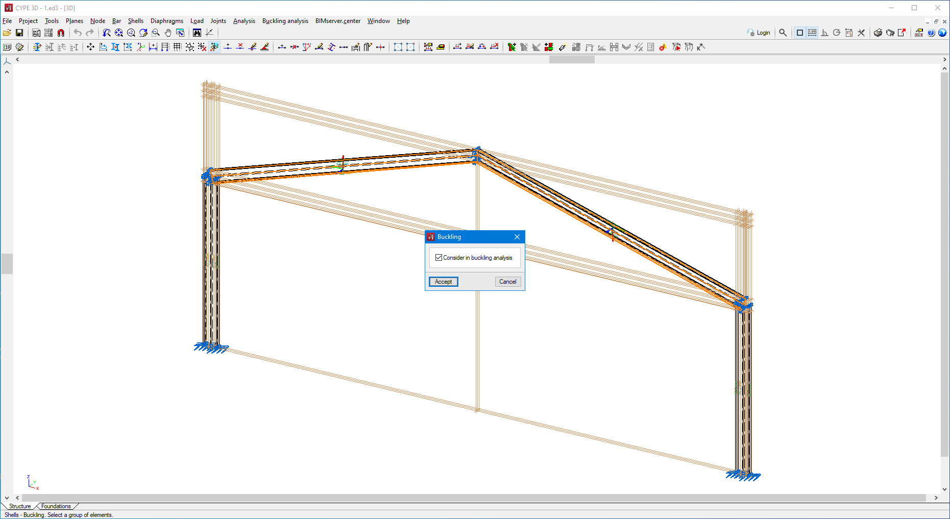
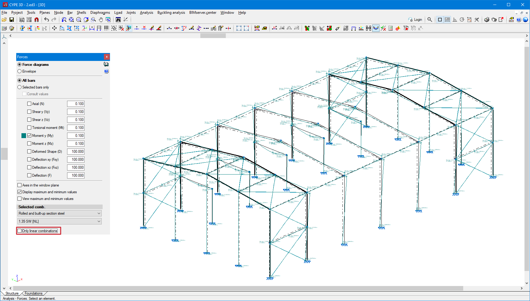
The options related to this new feature can be found in the new "Buckling analysis" menu.
Combinations for the buckling analysis
The stability of the structure must be analysed by load combinations. Just as for the non-linear analysis, the load combinations are defined based on the loadcases defined in the job data.
The program allows users to define the combinations to be analysed in three ways:
- By manually entering each combination.
- By automatically generating all possible combinations from the situations defined in the project.
- By analysing the results obtained from a linear analysis. In this case, the combinations in which the highest axial compression is produced are added to the bars of the structure depending on user-defined conditions.
Analysis
For the buckling analysis, users can define the number of buckling modes to be analysed and filter them by the maximum eigenvalue. The number of discretisation spans of the bars or the maximum length of each span can also be set.
For steel bars, users may indicate the minimum percentage of axial compression force below which a bar will not be included in the buckling analysis.
Assigning buckling coefficients
The program automatically analyses the buckling coefficients for each bar considered in the analysis. These coefficients can be assigned immediately after the buckling analysis, or by means of the "Assign buckling coefficients" option.
From the factors of both the critical load and the acting axial force, the program assigns the buckling coefficients. The participation analysis allows the buckling modes affecting each bar to be determined in order to analyse and assign the buckling coefficients.
Viewing the results
The buckling analysis results can be checked for each combination and buckling mode through the "Buckling modes" option. The program allows users to visualise both the deformation and the participation coefficient of each bar.
Buckling in bars
When defining the buckling data of a bar, users can indicate whether or not it will participate in the buckling analysis and, in case of updating the coefficients from the analysis results, which buckling coefficients will be updated.
Reports
The program allows the following reports to be generated:
- Buckling modes by analysis combination.
- Extended report of buckling modes for each bar.
- Summary report of the most influential buckling modes for each bar.
- Published on
- 2024.d
Non-linear analysis to consider "Bars only in tension" and "Uplift at supports" (new modules)
Up until version 2024.d, CYPE 3D designed structures with linear analysis, meaning that all elements only had linear behaviour. Now, as of version 2024.d, elements with non-linear behaviour will also be implemented, along with the non-linear analysis.
Elements with non-linear behaviour implemented in this update are bars that only work in tension and supports with uplifts. The non-linear analysis of these two elements is part of two CYPE 3D modules ("Bars only in tension" and "Uplift at supports"), which means that, in order to be able to perform this analysis, the user's license must include them. Furthermore, users must also have the "OpenSees analysis engine" in their license.
Non-linear combinations
In the non-linear analysis, a superposition of loadcases is not possible, so users must perform an analysis of the model for each load combination to be studied. Therefore, the load combinations are defined on the basis of the loadcases defined in the job data and the types of combinations to be used for checking the elements of the structure are indicated for each of them.
The program allows users to define the combinations to be analysed in three ways:
- By manually entering each combination.
- By automatically generating all possible combinations from the situations defined in the project.
- By analysing the results obtained from a linear analysis.
Analysis
The program shall offer the option to perform the non-linear analysis when non-linear combinations have been defined and/or elements with non-linear behaviour have been entered into the model.
In the linear analysis, the behaviour of the non-linear elements shall be considered linear. A non-linear analysis can be carried out without having previously defined the combinations, in which case the program will determine the combinations that need to be analysed from the results of the linear analysis.
The checking of the bars is carried out with the results available after the analysis. If both linear and non-linear results are available, the program combines the results of both types of analysis according to the types of combination that apply to each element.
Viewing the results
As well as being able to view the results by loadcase and by combinations, as of this version, the results by non-linear combinations can also be checked. When checking by combinations, if a combination has been analysed as non-linear, it will be indicated with the suffix "NL". The results of the linear analysis for that combination can also be checked by ticking the "Only linear combinations" option.
Bars only in tension (new CYPE 3D module)
To consider a bar that works only in tension, enter a generic type of bar and, in the new "Behaviour" option, select the "Only tension" value.
Uplift at supports (new CYPE 3D module)
The program allows users to define the non-linearity of the supports for two types of elements. For nodes with external fixity, the working direction of the elastic restraint can be specified for each restrained degree of freedom.
For shells with subgrade modulus, users can specify whether the behaviour is "Linear" or "Only compression".
Reports
The program allows users to generate force reports for non-linear combinations for nodes, bars and shells.
- Published on
- 2024.d
Implementation. SIST EN 1993-1-3:2007/A101:2009 (Slovenia)
Slovenian national annex to Eurocode 3: Design of steel structures. Part 1-3: General rules. Supplementary rules for cold-formed members and sheeting.
Implemented in CYPECAD and CYPE 3D.
- Published on
- 2024.c
Implementation. SIST EN 1993-1-1:2005/A101:2006 (Slovenia)
Slovenian national annex to Eurocode 3: Design of steel structures. Part 1-1: General rules and rules for buildings.
Implemented in CYPECAD and CYPE 3D.
- Published on
- 2024.c
Implementation. SIST EN 1992-1-1:2005/A101:2006 (Slovenia)
Slovenian national annex to Eurocode 2: Design of concrete structures. Part 1-1: General rules and rules for buildings.
Implemented in CYPECAD and CYPE 3D.
- Published on
- 2024.c
Implementation. ABNT NBR 6118:2023 (Brazil)
"Norma Brasileira ABNT NBR 6118:2023. Projeto de estruturas de concreto".
Implemented in CYPECAD and CYPE 3D.
- Published on
- 2024.c


