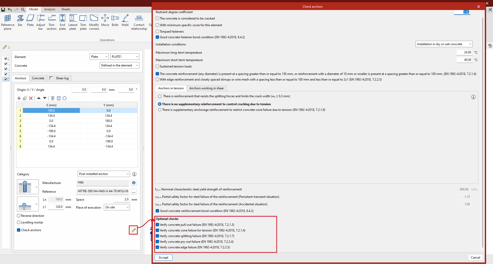
Update history​

CYPE Connect

Plate edge reference plan

As of version 2024.c, the "Reference plane" operation includes the "Edge" option to define reference planes on the edge of a plate.

Reference plan at the intersection between a bar and the envelope of another bar

As of version 2024.c, the "Reference plane" operation includes the "Intersection (Envelope)" option to define reference planes at the intersection between a bar and the envelope of another bar. This plane can be used as a reference for attaching plates, adjusting bars, etc.

Options existing up to 2024.c allow planes to be defined in any position, the advantage of using these new options is that the position of the plane is referenced to other elements so that if the dimensions or the position of the bars change, the position of the plane will also change. This is particularly useful when combined with the use of the connection library.

Reference plan at the intersection between a bar and one of the plates in another bar

As of version 2024.c, the "Reference plane" operation includes the "Intersection" option for defining reference planes at the intersection between a bar and one of the plates in another bar.

Reference plan in the bisector of two bars

As of version 2024.c, the "Reference plane" operation includes the "Bisector" option to define reference planes on the bisector of the two bars defined by the user. This plane can be used as a reference for attaching plates, adjusting bars for splices, etc.

"Move" operation

A new operation has been implemented to move bars or plates taking another element as a reference. This operation has two options, to move in the direction of the "z" axis or to move in the "xy" plane of the selected element. By means of these movements, the position of one element is linked to another. Should the reference element change its dimensions or position, the selected element will automatically move with it.

  • In the Z axis
    Moves a plate or a bar, starting from the selection of one of its plates, in parallel until one of its faces attaches to the face of another element. To perform this movement, both faces must be parallel.
  • In the XY plane
    Moves a plate, in its plane, until one of its edges reaches the plane defined by the face of another plate. It also moves a bar, from the selection of one of its plates, in the plane of the plate until one of its edges reaches the plane defined by the face of another plate.

Installation in German and Japanese

As of 21 September 2023, all downloads of the CYPE Connect and StruBIM Steel applications (versions 2024.b and later) from the the BIMserver.center platform will be available for installation in German and Japanese.

These applications can now be installed in the following languages:

  • Catalan
  • English
  • French
  • German
  • Italian
  • Japanese
  • Polish
  • Portuguese
  • Russian
  • Spanish

Installation modes (professional, campus, evaluation, temporary license)

All CYPE programs can be installed in their different versions (Professional Version, Evaluation Version, Campus Version, Temporary License). In previous versions, users could only choose the type of version to be installed from the classic CYPE menu.

As of version 2024.a, the selection of version types has been implemented in all CYPE programs on the BIMserver.center platform.

As of version 2024.d, this selection can be made during the installation of all CYPE programs, regardless of where they are downloaded.

Optimising the use of sheets

A series of optimisations have been implemented in version 2024.b in the use and management of sheets. This reduces waiting times when accessing the sheets and using their tools.

Defining the default settings in "Design options"

As of version 2024.b, the "Design options" panel includes the "Save as default settings" option. If this option is activated and the panel is accepted, all the settings in this dialogue are saved as default values, so that any subsequent new job will initially have the same values.

Deleting continuous dimensions intermediate points

An option to delete continuous dimensions intermediate points has been implemented. When selecting the "Modify geometry" option and clicking on a continuous dimension, the dimension intermediate points will be shown in red. If an intermediate point is selected, it will disappear and the two adjacent sections will be connected.

Automatic dimensioning

In version 2024.b, sections and plates can be automatically dimensioned in part sheets, and plates can be automatically dimensioned in connection sheets. For this purpose, in the "Insert predefined views" dialogue ("3D Scene" > "Insert predefined views"), the "Dimension" section has been implemented. Here, the "Dimension style" is defined. When accepting the "Insert predefined views" dialogue with the "Dimension" option activated, the dimensions of the inserted predefined views of part sheets are automatically added along with the dimensions of the predefined views of plates on connection sheets.

Implementation. ANSI/AISC 360-22 (LRFD)

"Specification for Structural Steel Buildings" (2022).

Implemented in:

  • CYPECAD and CYPE 3D for analysing and checking rolled and reinforced steel sections.
  • CYPE Connect and StruBIM Steel for analysing and checking steel connections.