The "Bill of quantities" tab now includes a status bar at the bottom of the main window that displays contextual information about what is being carried out in the application.

The "Bill of quantities" tab now includes a status bar at the bottom of the main window that displays contextual information about what is being carried out in the application.
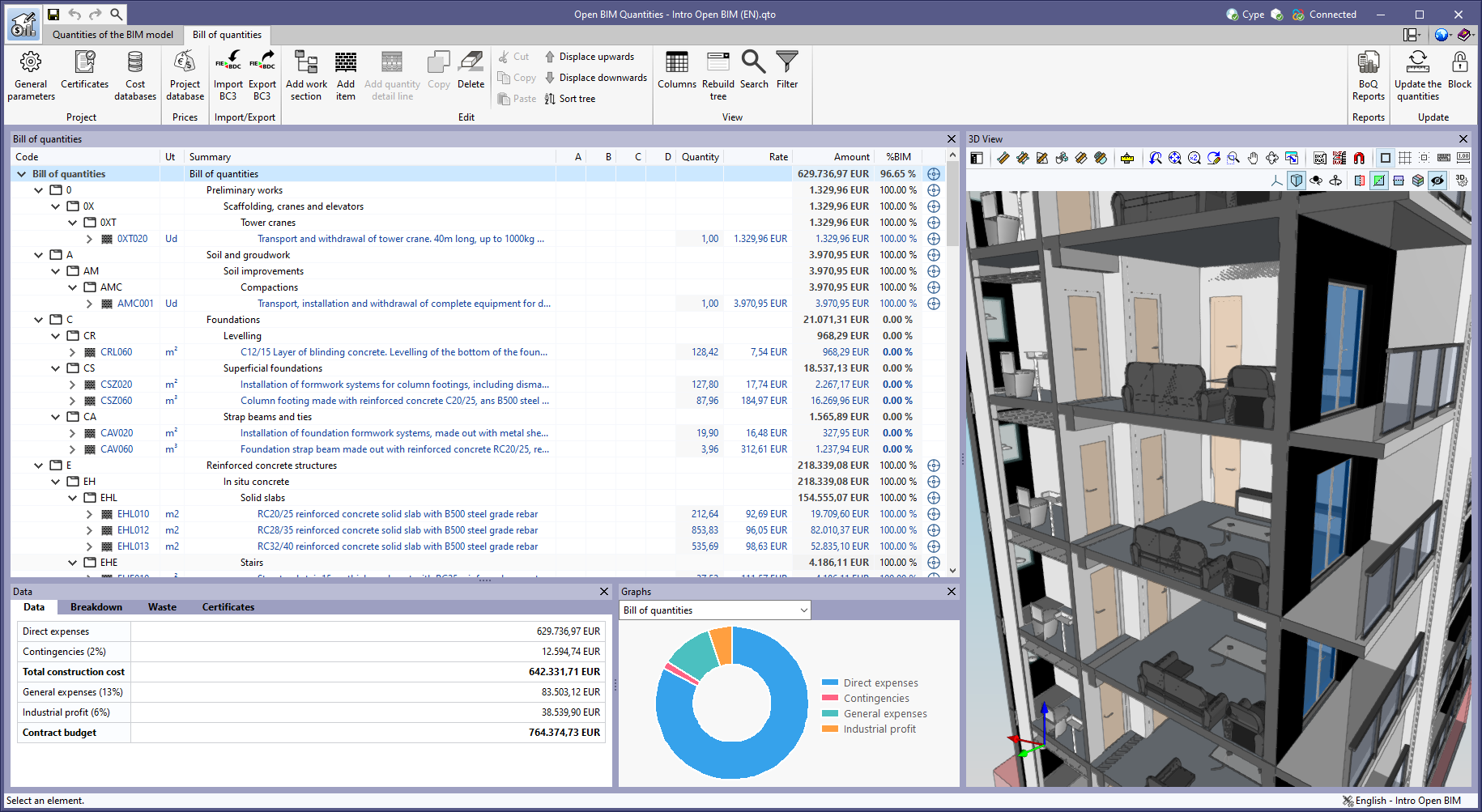
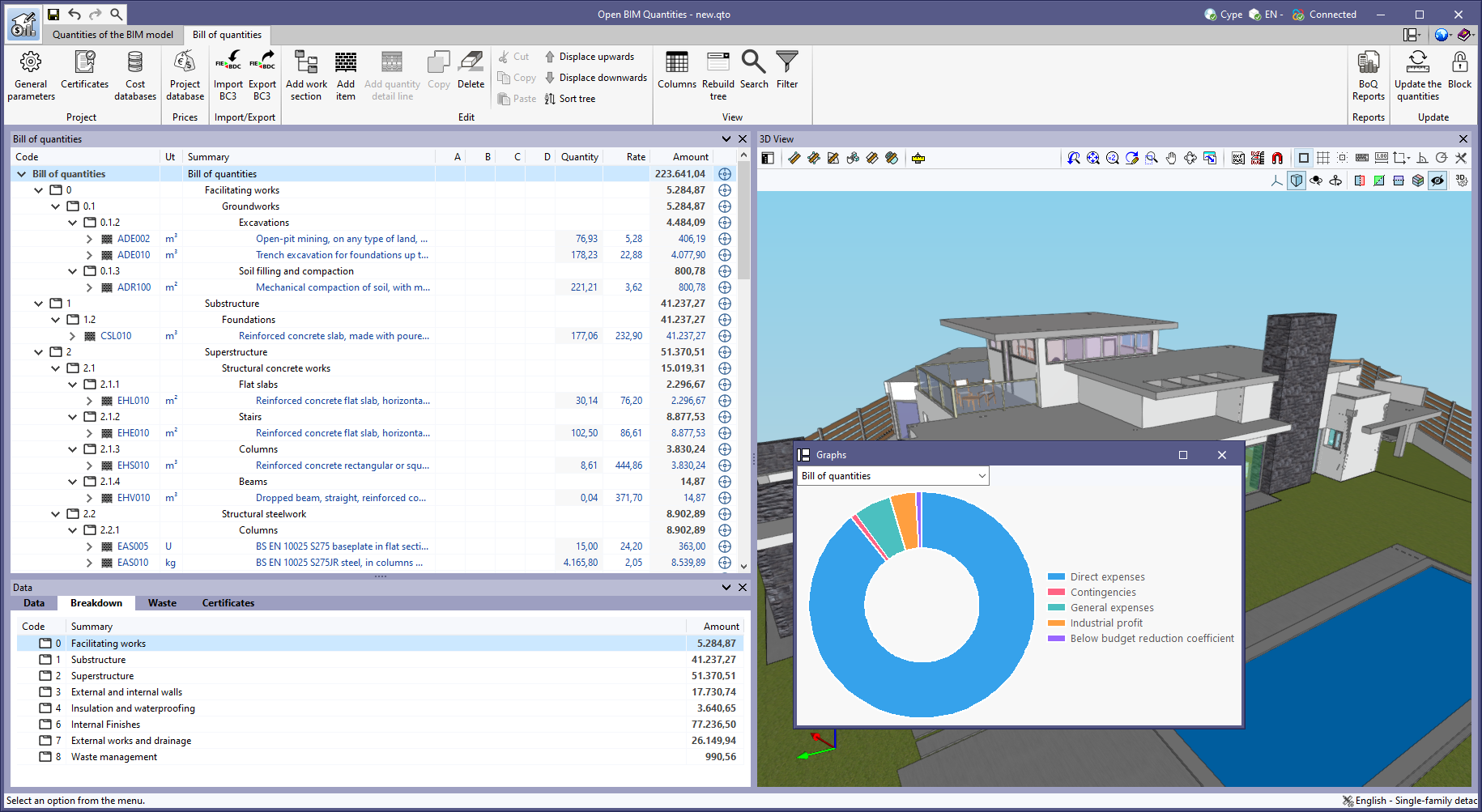
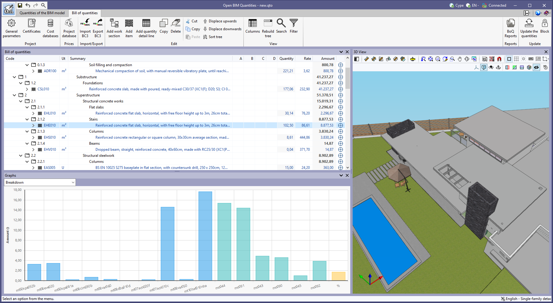
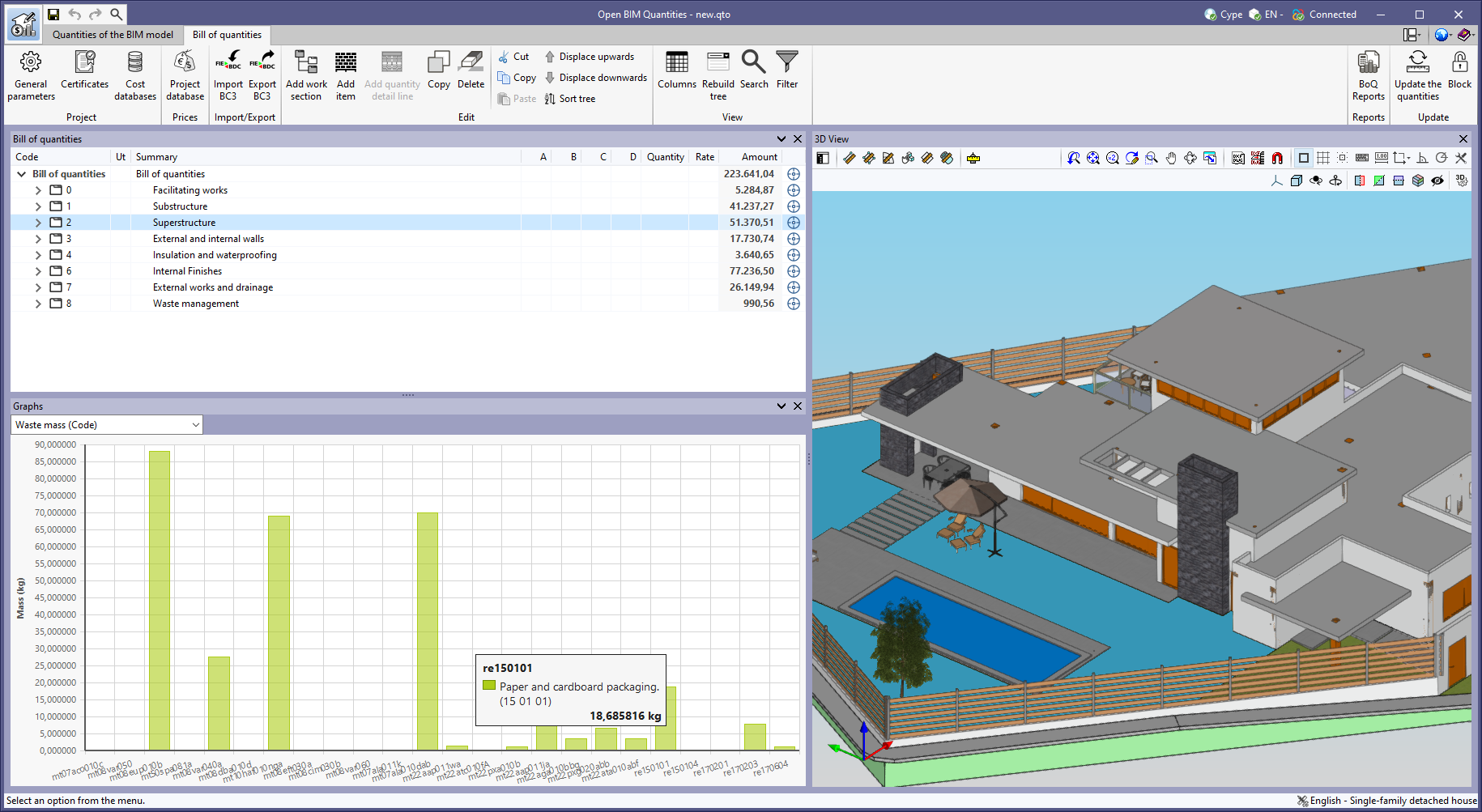
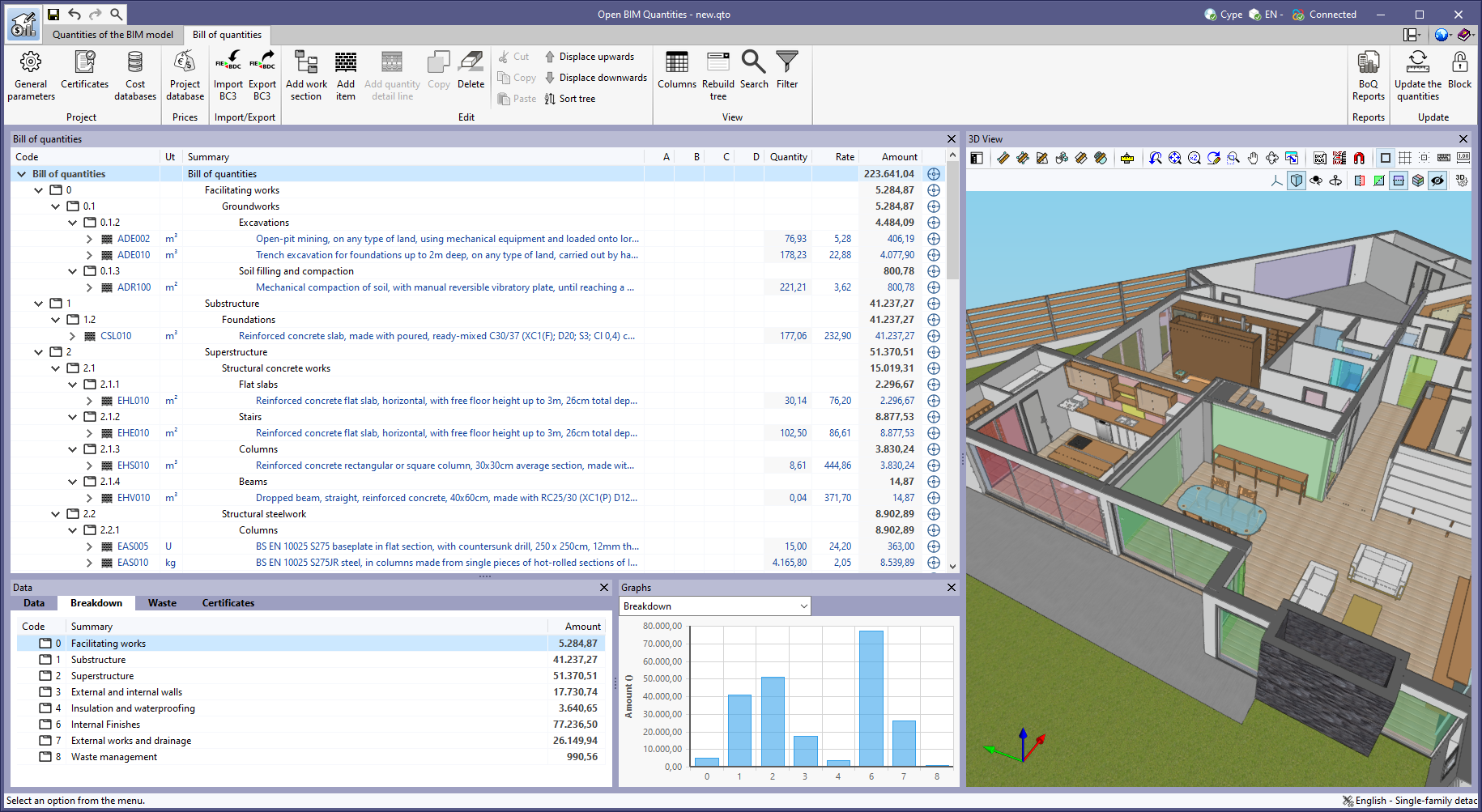
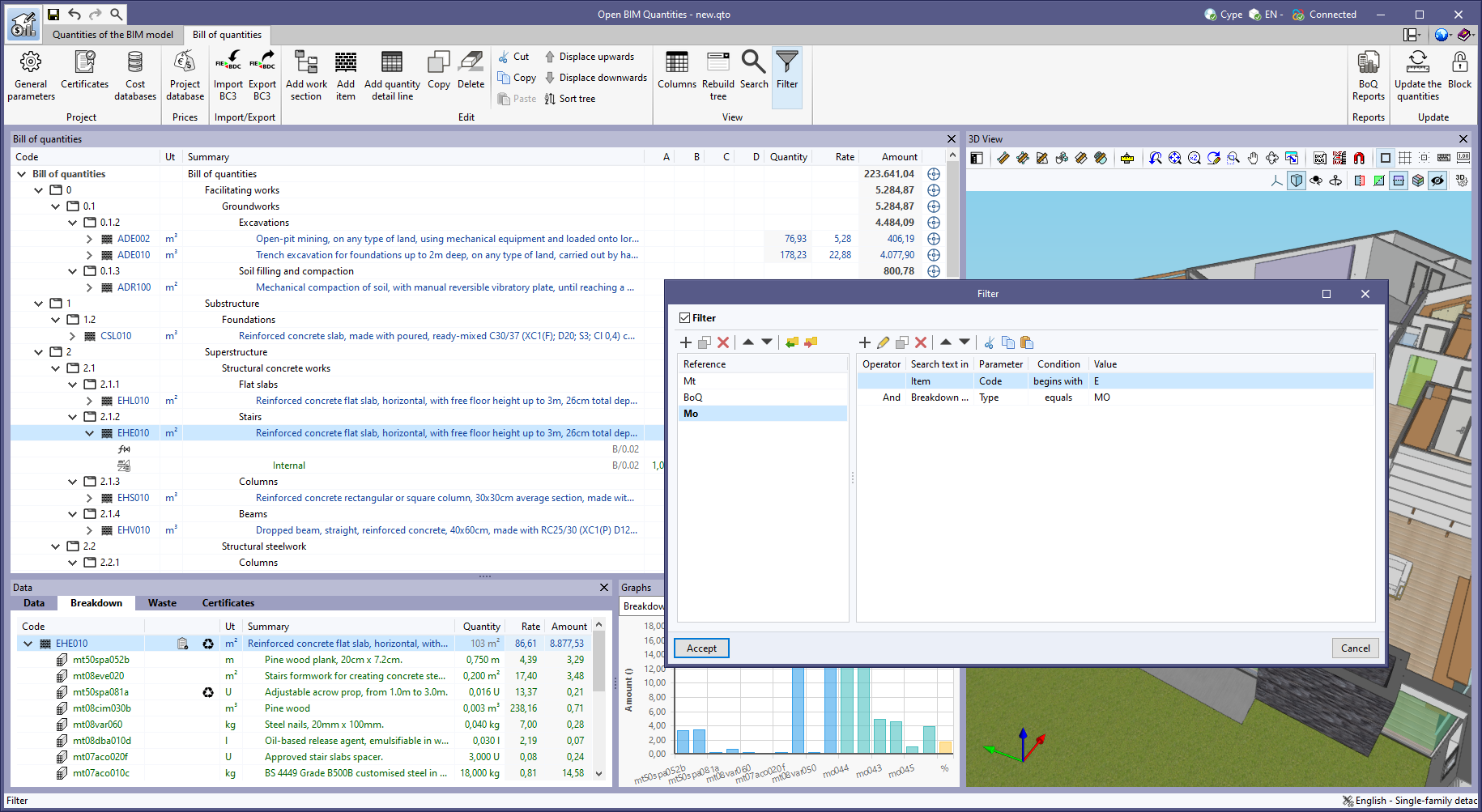
As of version 2023.g, the bill of quantities data can now be displayed graphically. For this purpose, the "Graphs" window has been added to the "Bill of quantities" tab. This window contains a drop-down list for selecting the graph to be displayed. In this version, the graphical representations (columns, circles, lines, etc.) of the following concepts are available:
The graph generated depends on the component of the bill of quantities table that has been selected. It is important to note that the available graphs depend on the type of element (work section, item or quantity detail line). By hovering the cursor over a section of the graph, a box will appear with the parameter reference and its value, allowing users to have a better understanding of the data shown.
Graphs with a key allow data sets to be hidden by left-clicking on their reference. When a set is not visible, its reference is crossed out and can be reactivated by clicking on it.


The "Breakdown" tab has been included in the "Data" window for the work sections of the bill of quantities. In previous versions, the "Breakdown" tab was only available for the items, where a table with their breakdown into resources is shown.
Now, the work sub-sections or items that are part of a work section can be displayed in this table.
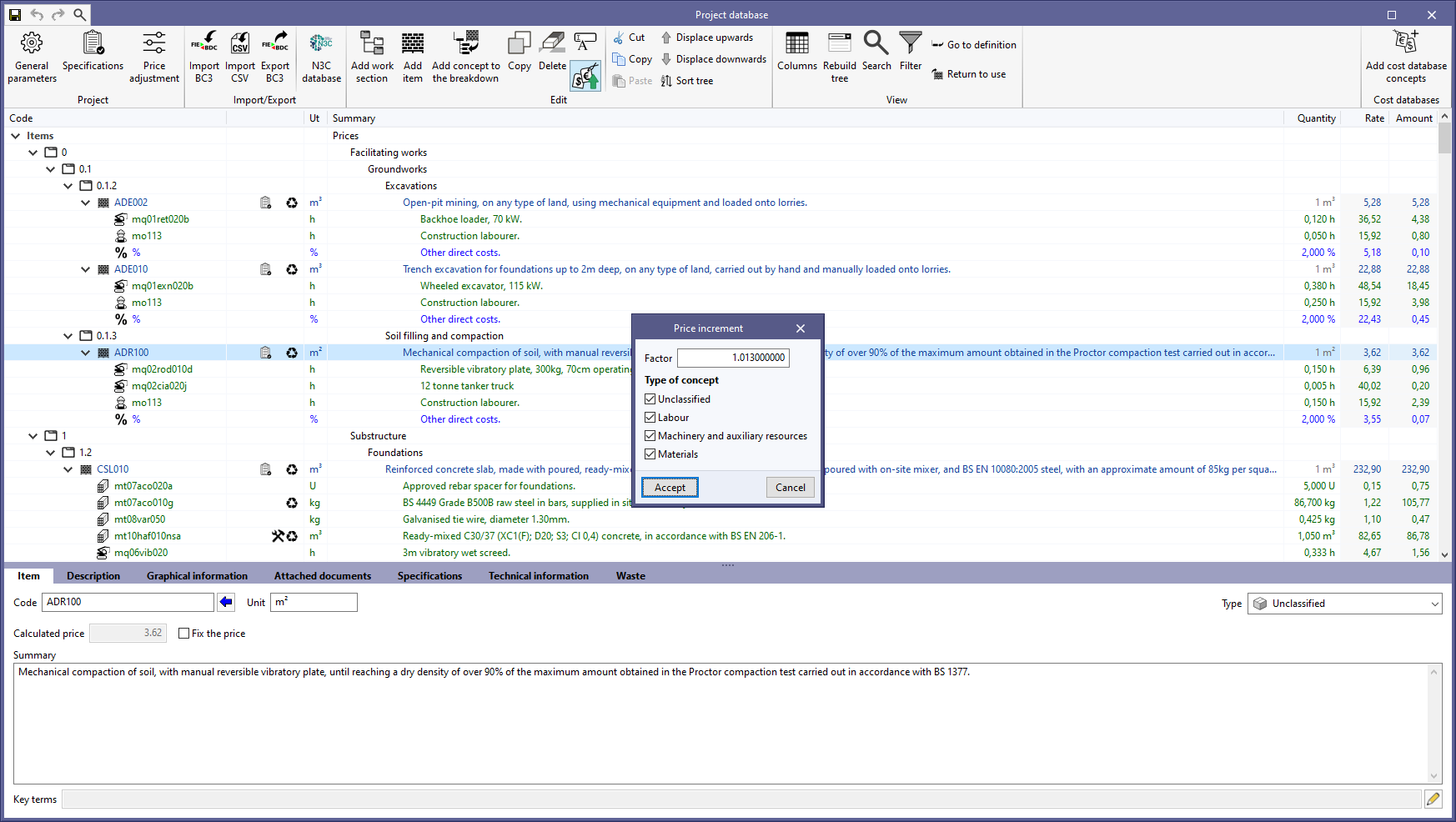
The "Price increment" option has been added to the editing window of the "Project database" or a "Cost database. With this tool, the prices of the concepts contained in the database can now be adjusted according to a "Factor". Furthermore, the application allows users to indicate the nature of the concepts ("Unclassified", "Labour", "Machinery and auxiliary resources" and "Materials") on which the operation is to be applied.
The following improvements have been made to the "Filter" option, available in the "View" group of the toolbar:
As of version 2023.f, the character set to be used when exporting the bill of quantities in the standard FIEBDC-3 format (.bc3) can be selected from the "Bill of quantities" tab in the applications that have it. For this purpose, the "Character set" field has been included in the export configuration window and has three options:
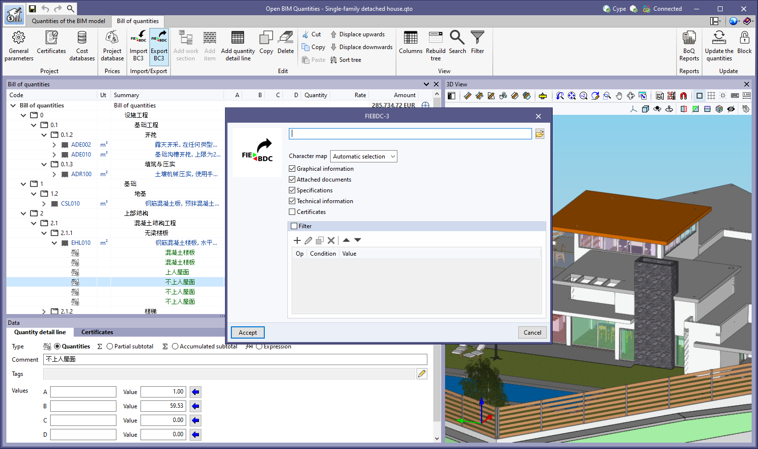
Thanks to the possibility of exporting and importing the bill of quantities in UTF-8 encoding, applications can now share bills of quantities that include Unicode characters. This establishes a fully multilingual environment for managing the project’s bills of quantities.
In the FIEBDC-3 standard, the character set is specified in the CHARACTER_SET field of the V record.
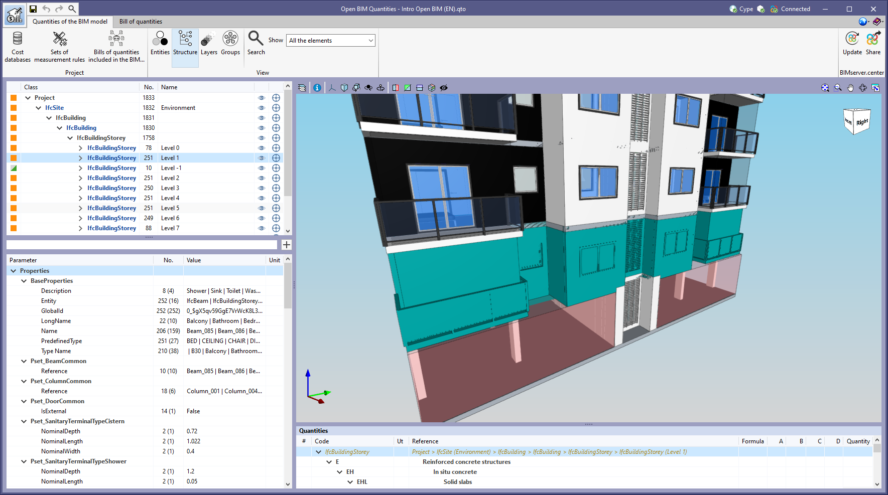
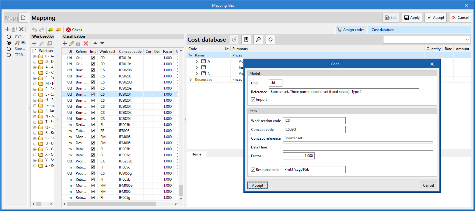
As of version 2023.e, applications with a "Bill of quantities" tab can map their model's elements to an item's resource. For this purpose, in the editing of a mapping file, the "Resource code" option has been added when components are modified in the "Classification" list. By activating this option, users can specify the resource code on which the quantity of the model element will be mapped. This will be added to the breakdown of the concept described by means of the "Concept code" and "Concept reference" fields.
When the resource indicated in the mapping file is a cost breakdown in the associated cost database, only the unit components of this breakdown shall be assigned to the concept.
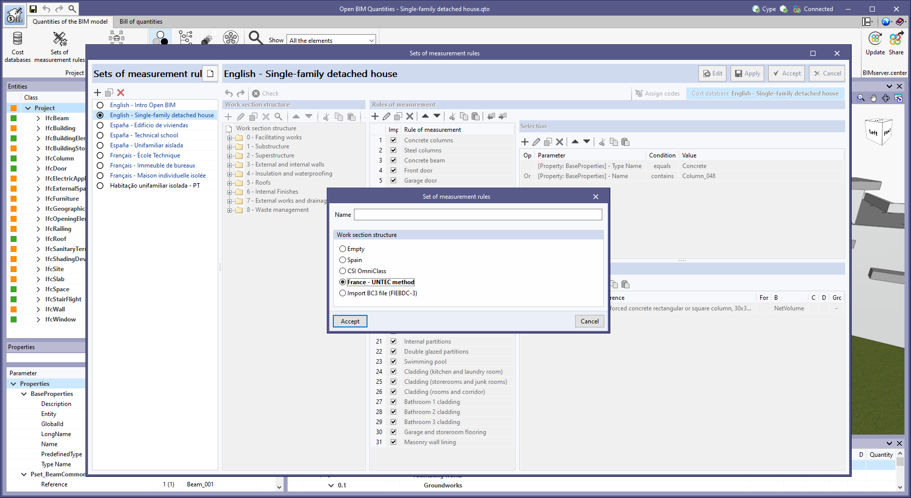
The predefined work section structure "France - UNTEC Method" has been added when creating a new "Set of measurement rules" (Open BIM Quantities) or a "Mapping file" (applications with a "Bill of quantities" tab).
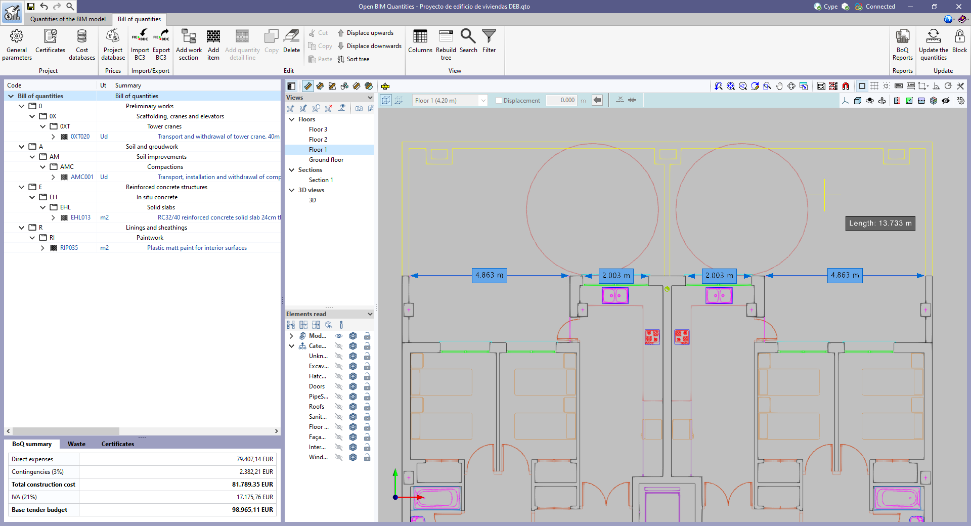
As of version 2023.e, some CYPE applications have a new dockable window system that replaces the main screen user interface. As a result, users can now customise the workspace to suit their needs.
The list of applications that have this dockable window system appears at the end of this new feature. In future versions, the number of applications with this window system will be increased.
Dockable windows can be moved and resized. They can be either floating windows, pinned to a location within the application's main dialogue box, dragged outside of it, or even moved to another monitor.
The window layout and display settings are saved when closing the application.
It is important to note that not all floating windows in an application are dockable windows. In order to tell them apart, the ![]() icon has been added to the title bar of windows that are dockable.
icon has been added to the title bar of windows that are dockable.
The following applications now include the new floating window environment in version 2023.e:
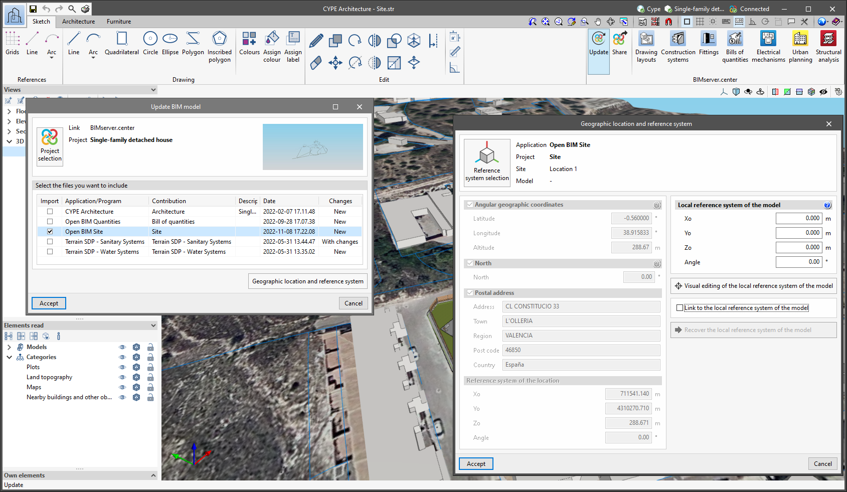
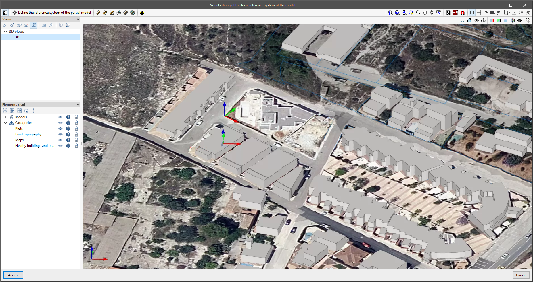
Since version 2022.a, the applications integrated within the Open BIM workflow via the BIMserver.center platform include a tool for managing project reference systems. This option is available from the configuration window that appears when linking or updating a BIMserver.center project via the "Geographic location and reference system" option. As of version 2023.d, the applications now allow users to run a graphical environment where they can visually define a reference system for their model. To do this, the "Geographic location and reference system" window now contains the "Visual editing of the local reference system of the model" option.
From the "Visual editing of the local reference system of the model" window, the origin and orientation of the reference system of the model can be indicated in the workspace with the "Define the reference system of the partial model" tool. Both the axes of the reference system of the model, which we have just entered and the axes of the reference system of the site can be viewed in the workspace. The latter appears with a "Site" tag.
To make it easier to define the reference system, the 3D models corresponding to the BIMserver.center project contributions selected during the linking process are displayed. The management of the visibility and object snaps of these models is carried out from the "Elements read" menu in the left sidebar of the window. The "Views" menu can also be found in the same options bar, from which different types of 2D and 3D views of the model can be generated. These tools can already be found in several CYPE applications. For more information on how they work, please refer to the User’s Manual for the 3D work environment tools available in CYPE applications.
Apart from 3D models, 2D drawings or plans can also be imported from CAD files (".dxf", ".dwg", ".dwf") or images (".jpeg", ".jpg", ".bmp", ".png", ".wmf", ".emf", ".pcx"). These files and object snaps are managed through the "DXF-DWG Template" and "Template object snaps" options accordingly.
Once the editing is complete, the coordinates and orientation of the reference system of the model with respect to the reference system of the site are moved to the corresponding fields in the "Geographic location and reference system" window.
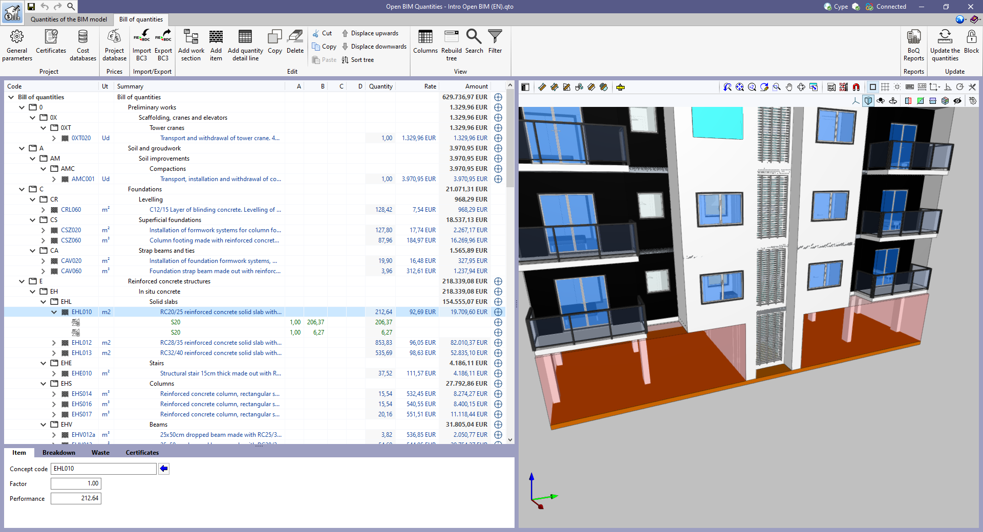
As of version 2023.d, all applications with a "Bill of quantities" tab now have a new set of tools that allow users to measure the work area. More specifically, the following options have been added:
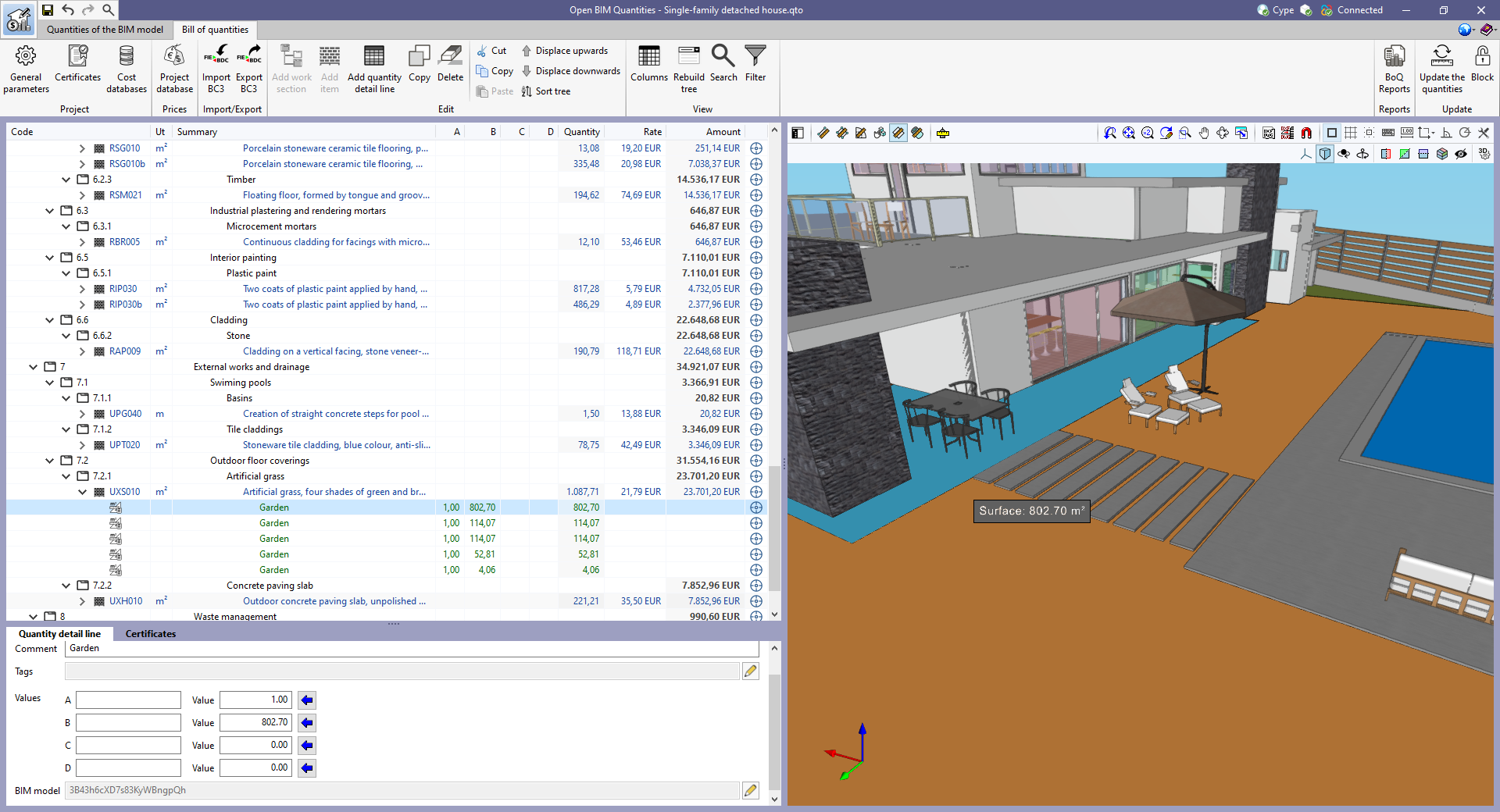
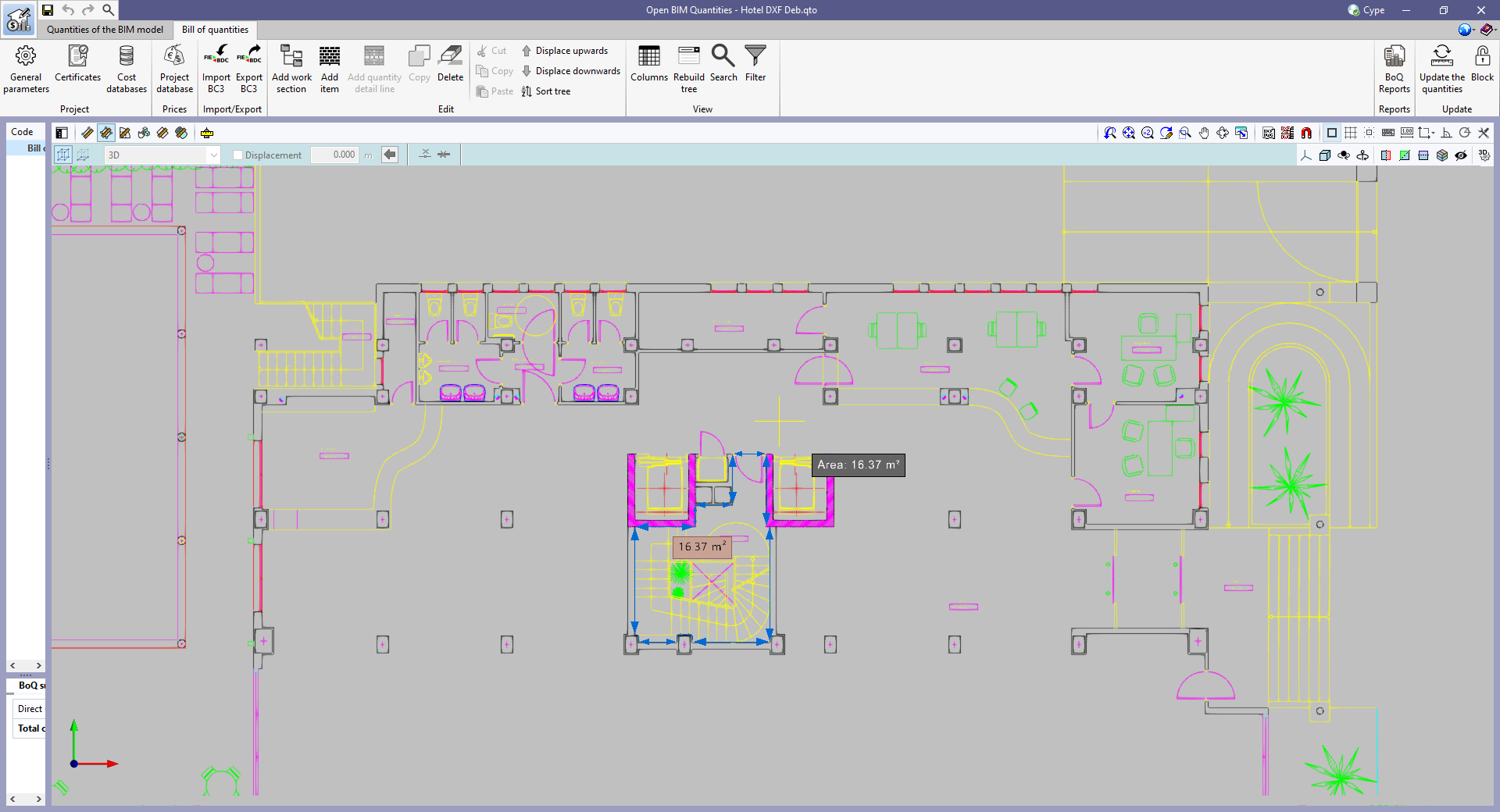
In order to make it easier to measure the quantities of the model, the work area has been modified to incorporate the 3D work environment tools that are already available in other CYPE Open BIM applications:
As well as measuring the 3D model, this new set of tools can be used to take measurements on plans or 2D drawings imported from CAD files (".dxf", ".dwg", ".dwf") or images (".jpeg", ".jpg", ".bmp", ".png", ".wmf", ".emf", ".pcx"). These files and the object snaps are managed through the "DXF-DWG Templates" and "Template object snaps" options respectively.
In order to use the measurements in the project's bill of quantities in a simple way, a button with a blue arrow has been added to the editing panel of the detail lines next to the editing window of each variable (A, B, C and D). Clicking it will assign the value of the measurement made on the work area to the variable.

The option to "Zoom" into the 3D model element has been added in the following cases: