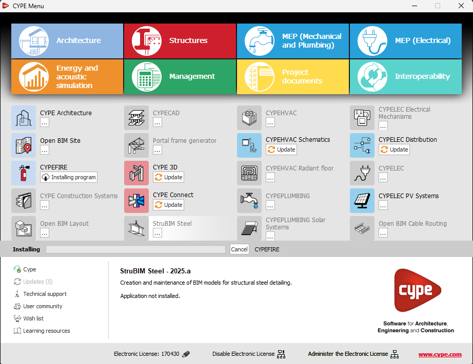
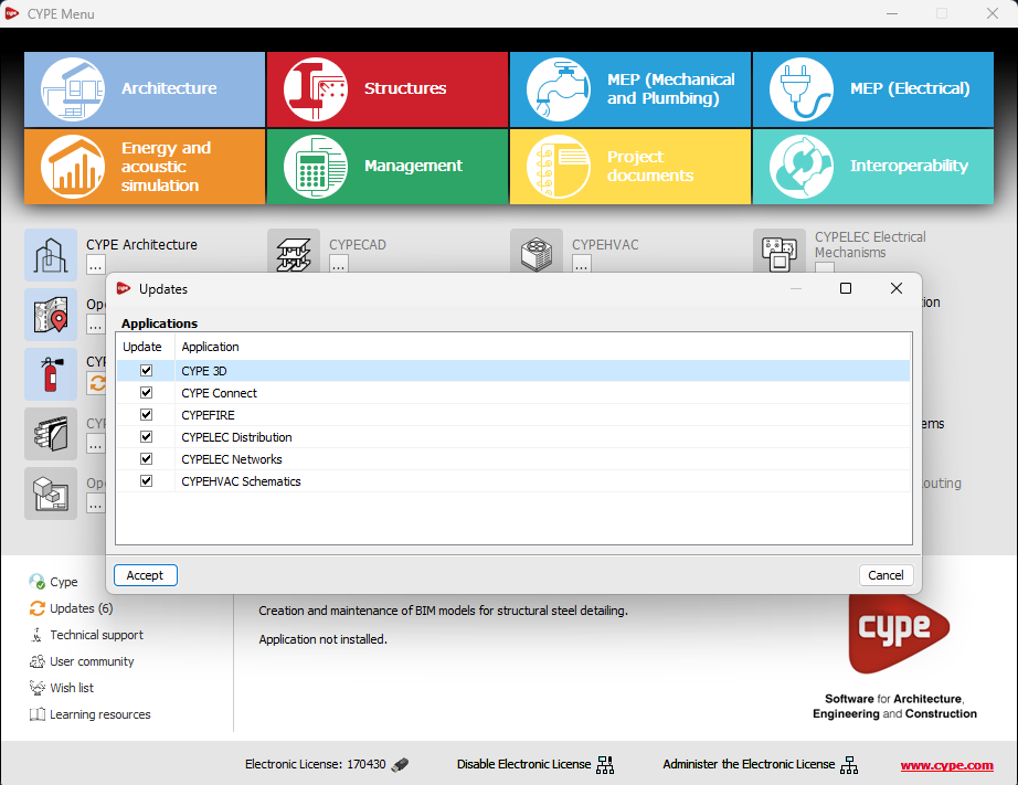
The "Updates" option has been implemented in the main CYPE Menu window. Thanks to this tool, multiple updates of installed applications can be carried out via the CYPE Menu.
When clicking on the “Updates” option, a window opens with a list of all installed applications. Select a set of them and, after clicking "Accept", the update process will start.
During this process, progress is displayed in the main CYPE Menu window indicating the current status of the update.
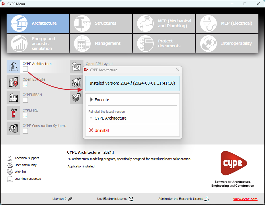
If an update is available for the CYPE Menu itself, it is shown below the list of applications to be updated. However, it is important to note that the update of the CYPE Menu is carried out on its own.
This new feature makes application maintenance easier, ensuring that the latest improvements are always available.