The following modifications have been made to the availability of the applications from the CYPE Menu.
New:
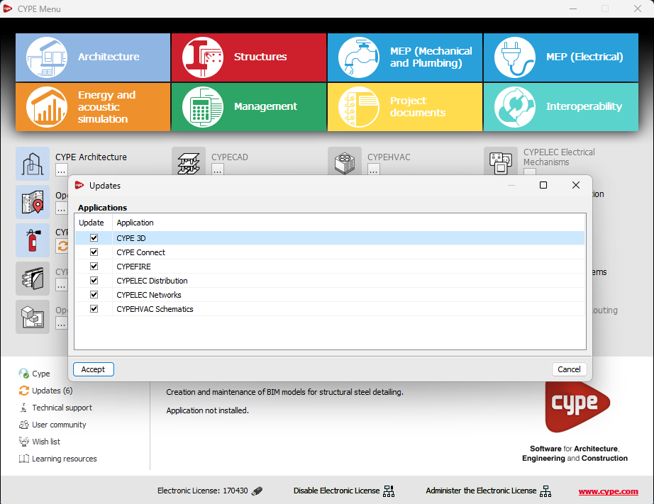
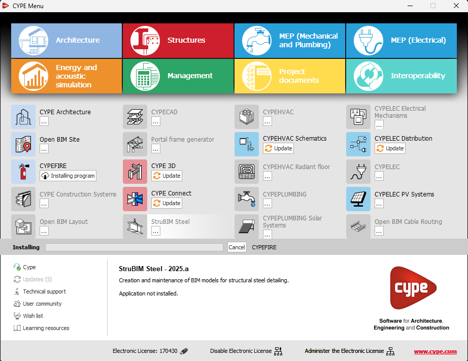
- CYPEHVAC Schematics
- ELODIE by CYPE (Only in the CYPE Menu in French)
Deleted:
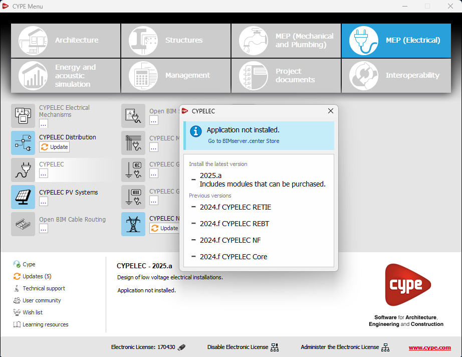
- CYPELEC Core, CYPELEC REBT, CYPELEC NF and CYPELEC RETIE. They are joined together in a single program called CYPELEC.
- CYPESOUND CTE, CYPESOUND NRA, CYPESOUND RRAE, CYPESOUND DRAPDE. They are integrated into CYPESOUND.
- CYPEURBAN. Available for download and installation from the BIMserver.center platform.
- IFC Uploader. New contributions can now be created directly from the project page on the BIMserver.center platform.
- CYPEFIRE FDS Viewer. CYPEFIRE FDS can be used to view FDS simulations.