The Spanish example job "Unifamiliar aislada" has been updated.


The Spanish example job "Unifamiliar aislada" has been updated.
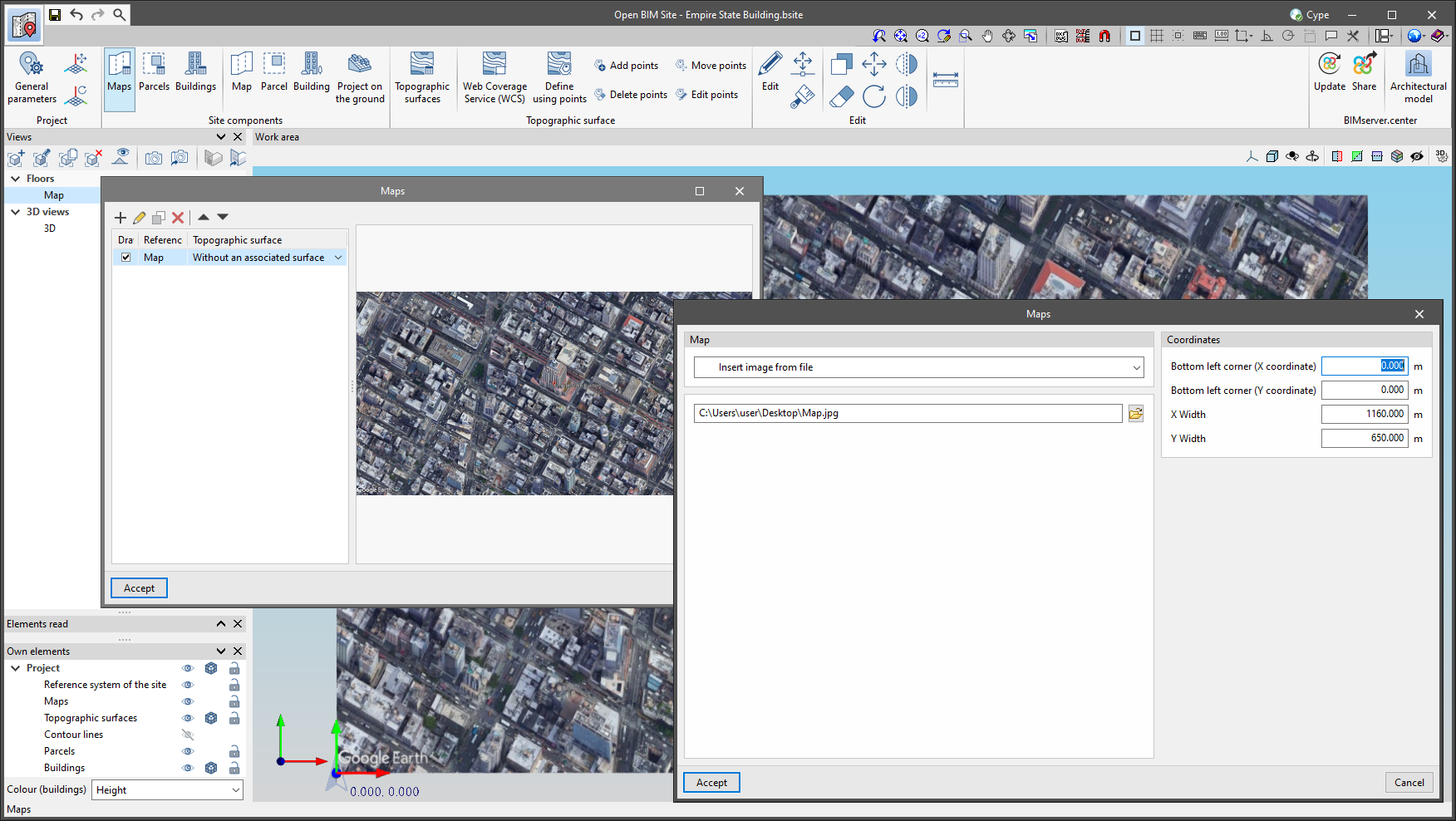
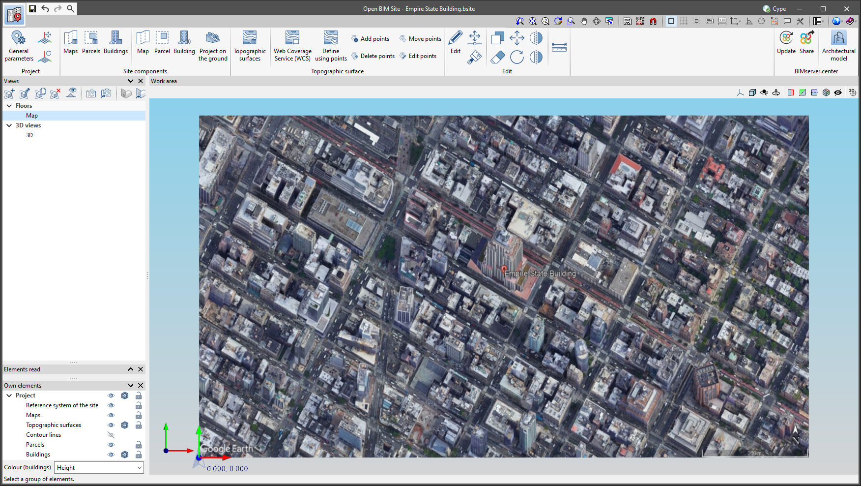
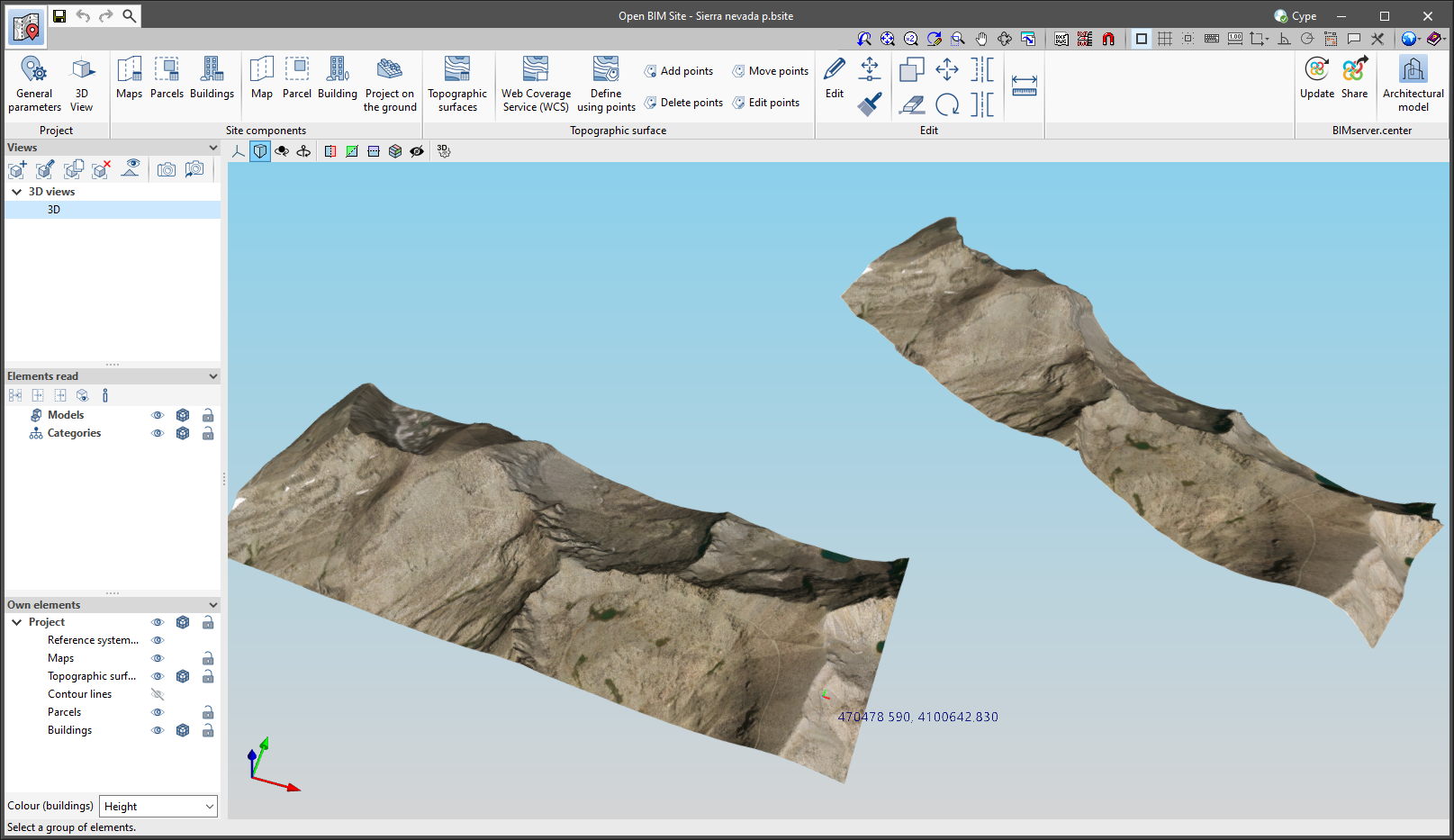
Up until now, maps of Open BIM Site projects had to either be obtained from one of the WMS services connected to the application or, if a file was available, the template system had to be used. As of version 2023.e, Open BIM Site allows maps to be imported directly from image files. To do this, the "Insert image from file" option has been added in the properties window of a map. When selecting it, the complete path of the image must be specified. The format of the image can be JPEG (".jpeg", ".jpg"), BMP (".bmp"), PNG (".png") or WMF (".wmf"). Additionally, as with the rest of the maps, users must specify the coordinates where the image will be inserted and the actual size of the image.
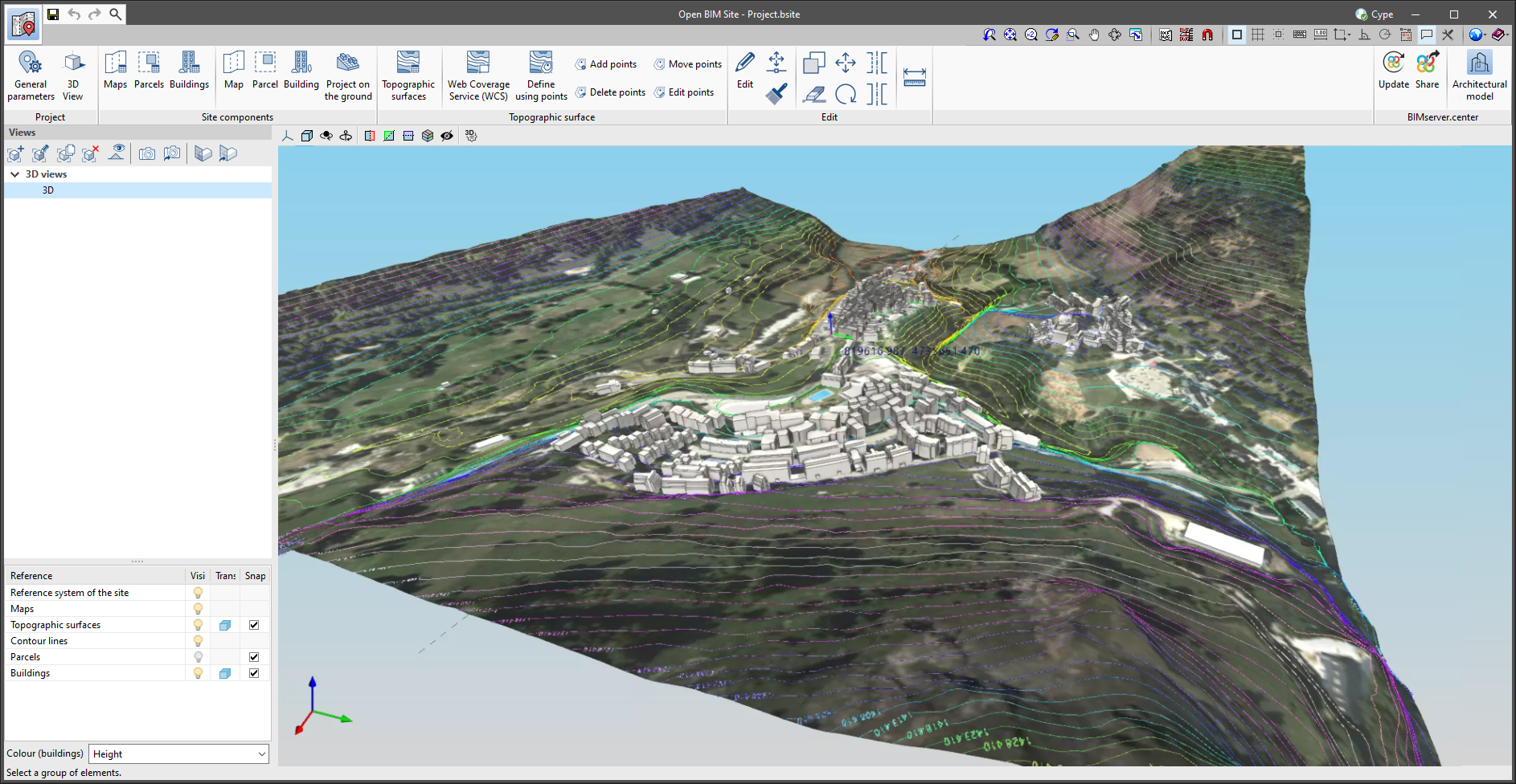
The main advantage of using the application maps over the template system of the drawing environment is that the maps can be projected onto the topographic surfaces and then exported to the BIMserver.center project.
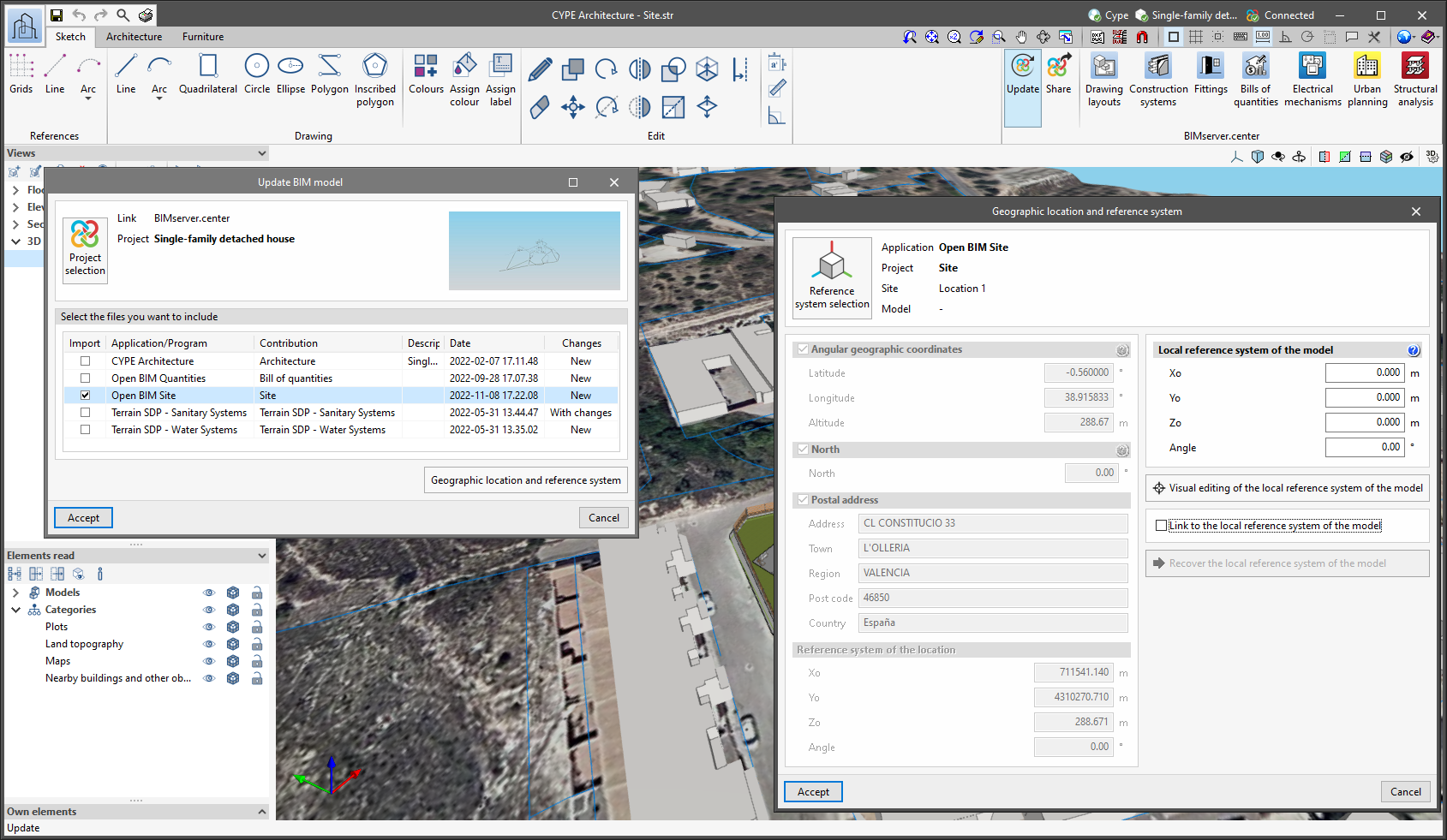
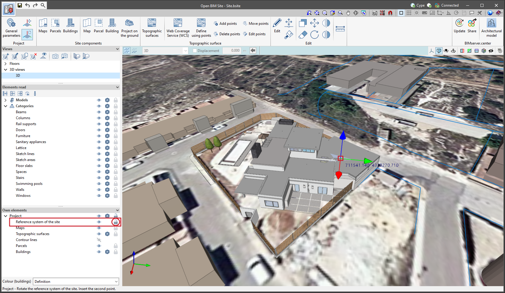
Since version 2022.a, the applications integrated within the Open BIM workflow via the BIMserver.center platform include a tool for managing project reference systems. This option is available from the configuration window that appears when linking or updating a BIMserver.center project via the "Geographic location and reference system" option. As of version 2023.d, the applications now allow users to run a graphical environment where they can visually define a reference system for their model. To do this, the "Geographic location and reference system" window now contains the "Visual editing of the local reference system of the model" option.
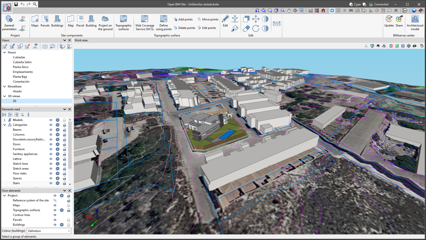
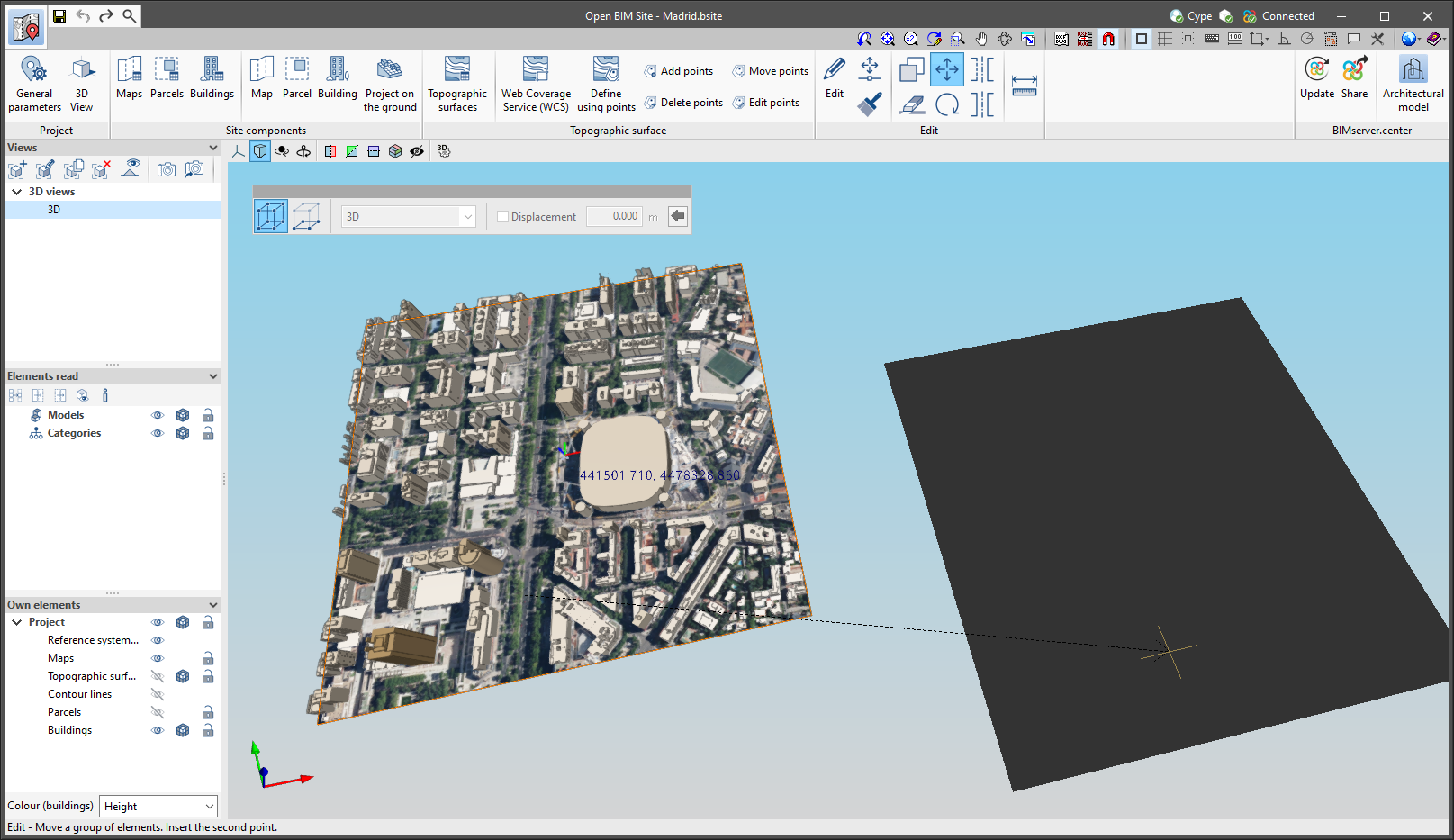
From the "Visual editing of the local reference system of the model" window, the origin and orientation of the reference system of the model can be indicated in the workspace with the "Define the reference system of the partial model" tool. Both the axes of the reference system of the model, which we have just entered and the axes of the reference system of the site can be viewed in the workspace. The latter appears with a "Site" tag.
To make it easier to define the reference system, the 3D models corresponding to the BIMserver.center project contributions selected during the linking process are displayed. The management of the visibility and object snaps of these models is carried out from the "Elements read" menu in the left sidebar of the window. The "Views" menu can also be found in the same options bar, from which different types of 2D and 3D views of the model can be generated. These tools can already be found in several CYPE applications. For more information on how they work, please refer to the User’s Manual for the 3D work environment tools available in CYPE applications.
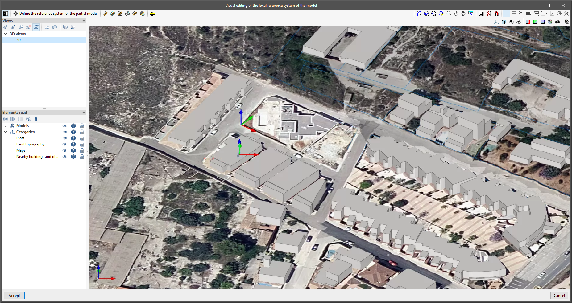
Apart from 3D models, 2D drawings or plans can also be imported from CAD files (".dxf", ".dwg", ".dwf") or images (".jpeg", ".jpg", ".bmp", ".png", ".wmf", ".emf", ".pcx"). These files and object snaps are managed through the "DXF-DWG Template" and "Template object snaps" options accordingly.
Once the editing is complete, the coordinates and orientation of the reference system of the model with respect to the reference system of the site are moved to the corresponding fields in the "Geographic location and reference system" window.
The "Adjust the elements associated with the site" option has been added to the "Reference system of the site" group in the "General parameters" menu. By selecting it and editing the values of the reference system origin of the site, the elements that make up the site model (topographic surfaces, maps, parcels, etc.) will be moved to adapt to the modification. This is how the application behaved in previous versions and, consequently, it is the default value of the option. By deactivating it, the values of the reference system origin of the site can be modified, but the components of the model will not be adjusted to this modification.

The following options have been added to the "Project" group in the application toolbar:
Thanks to these tools, the origin and orientation of the reference system of the site can now be defined graphically.
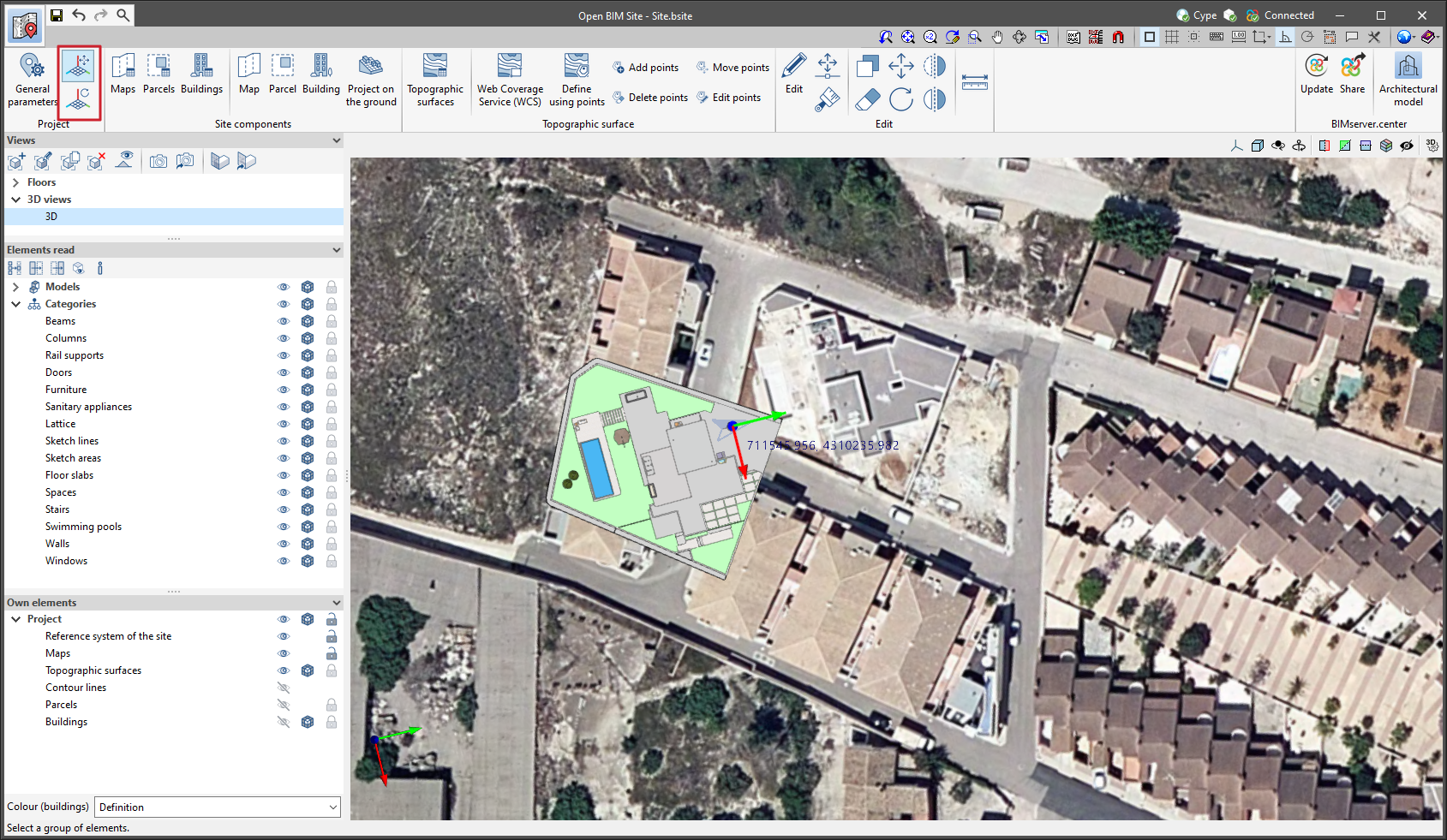
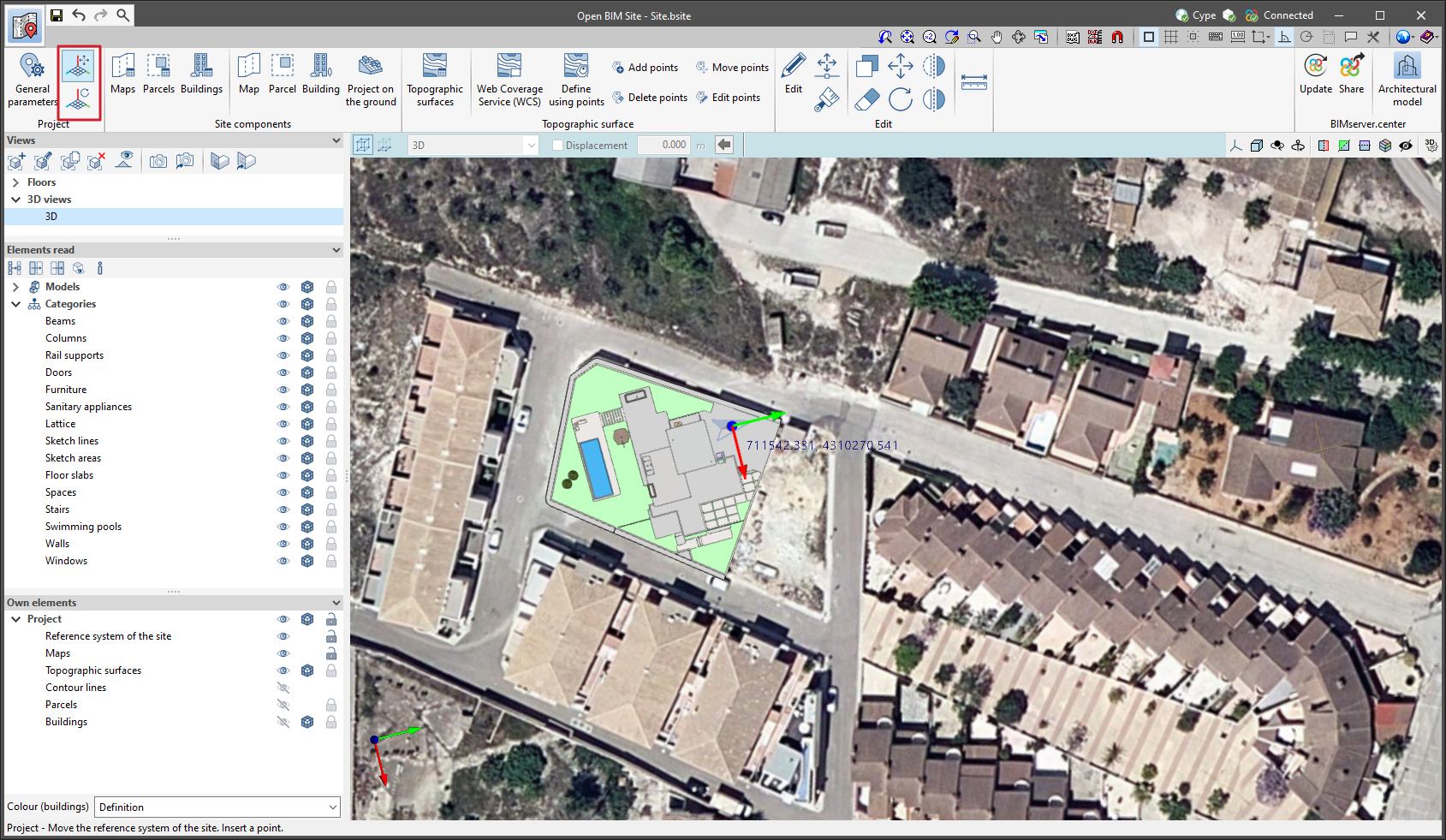
As of version 2023.d of Open BIM Site, object snaps can be used on the reference system origin of the site. To activate or deactivate it, the "Snap" option has been added to the "Reference system of the site" section in the "Own elements" menu found in the left-hand sidebar of the application. This improvement makes it easier to use the editing tools on the site model components.
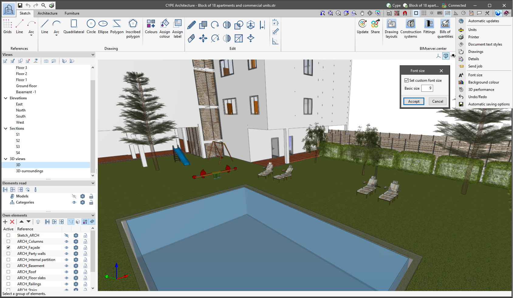
The "Font size" option has been added to the general configuration menu of the applications. This tool allows users to increase or decrease the basic size of the font used in the user interface of the programs. Thanks to this implementation, the accessibility of the applications has been improved while also ensuring the correct visibility of the content on devices with different screen resolutions.
To enter a "Basic size" the "Set custom font size" option must be checked. The size users can enter is the application's basic font size. Any other font sizes that may exist in the program's interface will be automatically modified proportionally according to the change in the basic size.
It is important to note that, as this is a common parameter, its modification will affect all installed CYPE tools.
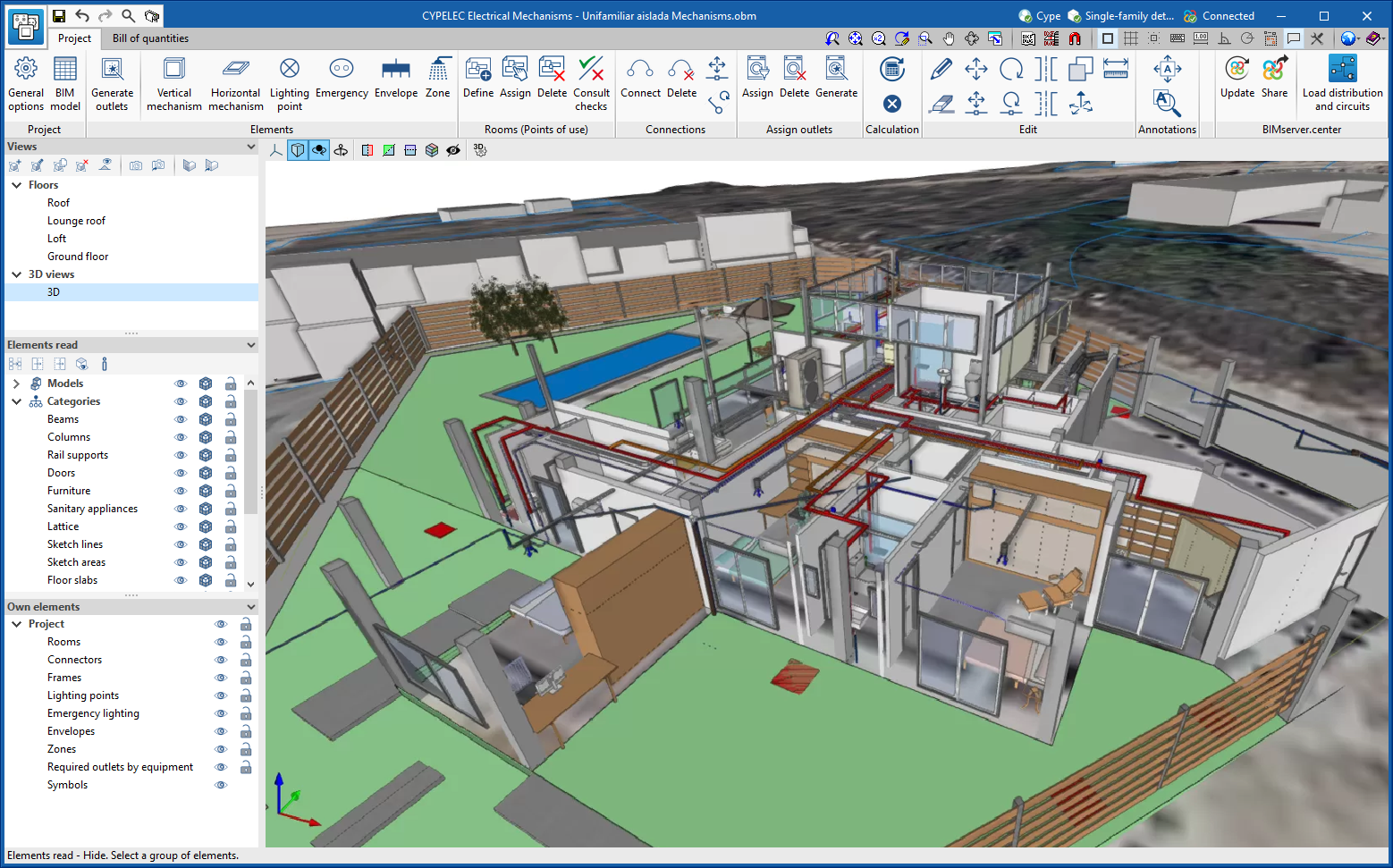
Since version 2020.f, applications with a 3D working environment include a floating toolbar to make it easier to enter or edit model components on the workspace. The options displayed in this toolbar depend on the active view and the element(s) being entered or edited.
This component is now anchored below the application toolbar. This makes better use of the available space in the user interface.
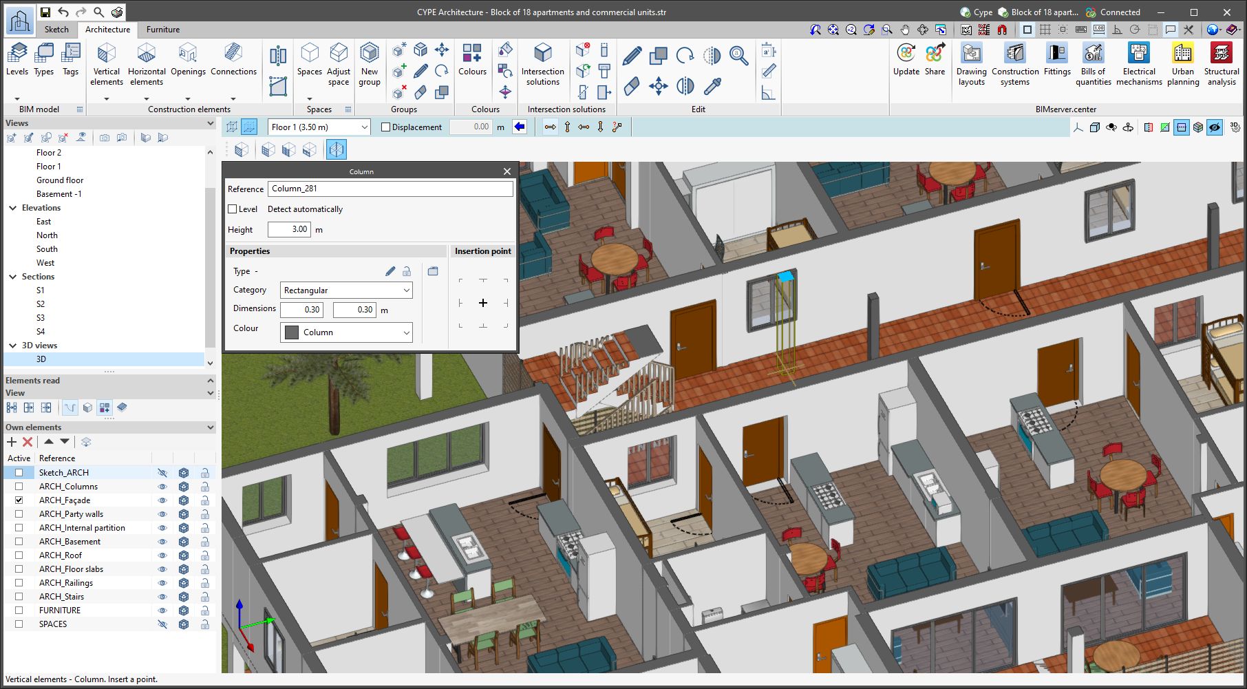
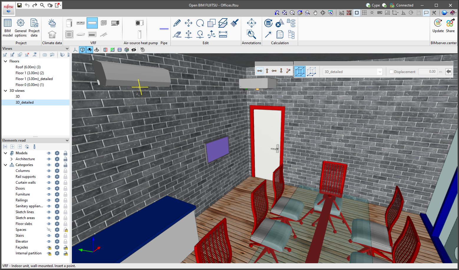
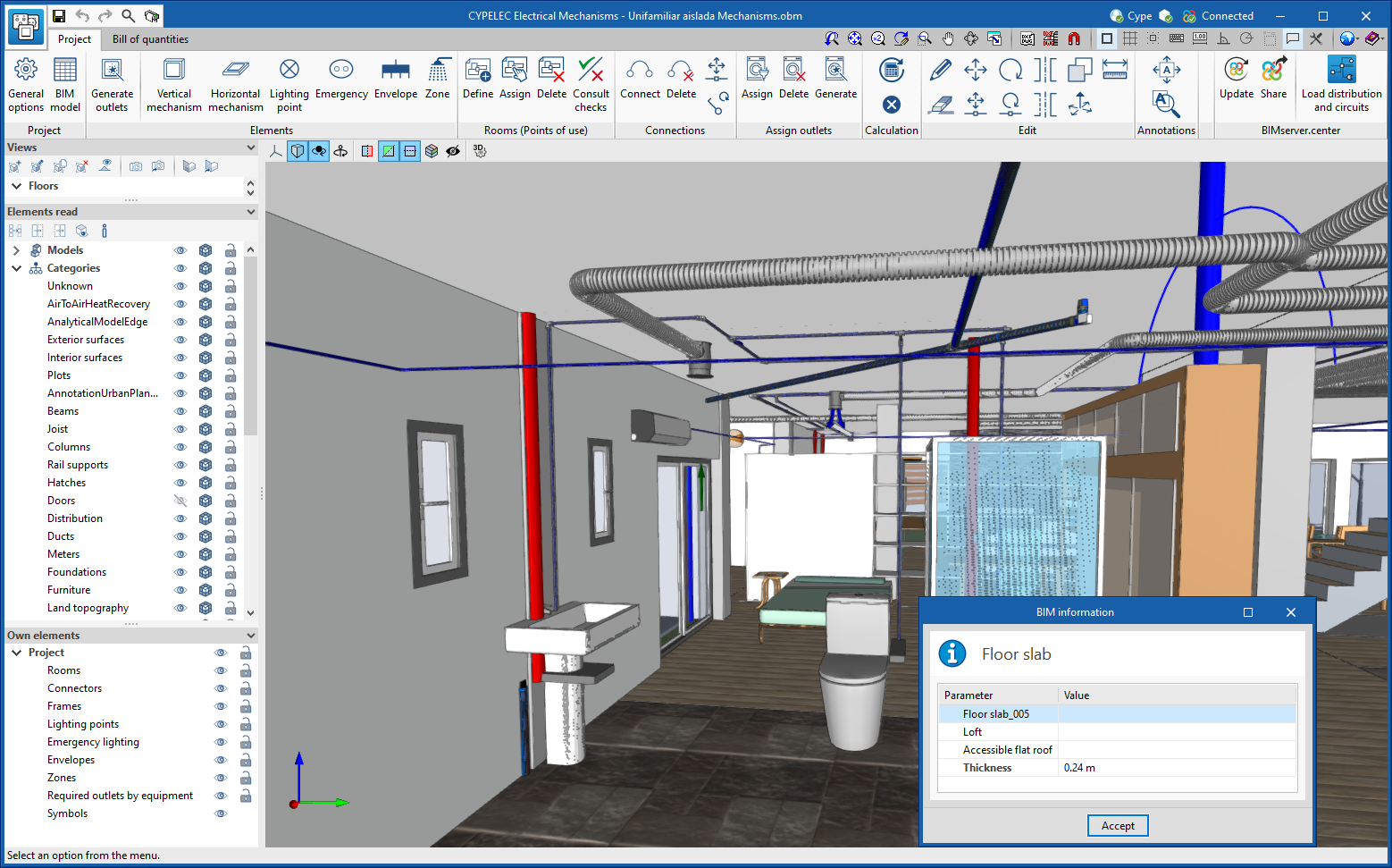
A new tool has been implemented in the user interface that is common in Open BIM applications with a 3D working environment. Now, the management of the elements from the digital model of the building, which comes from the associated BIMserver.center project, is carried out from the "Elements read" menu located in the left sidebar of the application.
The elements read are structured in the form of a tree based on two classification types: "Models" and "Categories". The organisation by "Models" allows users to inspect each contribution linked to the job and each associated 3D model within it. On the other hand, the "Categories" group the "Elements read" into families according to their features. Next to each tree component, three buttons are displayed to control the visibility, the display mode (solid, transparent or wire) and the object snap. It should be noted that the organisational settings applied to the organisation by "Models" prevail over those indicated by "Categories".
Applications can have default visibility and object snap settings when creating a new view. Furthermore, when entering new components with the tools in the program, the application itself can force the activation or deactivation of the visibility and object snaps of certain categories. When this happens, a yellow padlock will be displayed next to the set options. When users finish using the tool, the tree will return to its original state.
In previous versions, the management of the visibility of BIM project models was carried out in the configuration panel of a view. As a consequence of this improvement, editing is now managed from the "Elements read" menu in the left sidebar and has therefore been removed from the previous location. However, in the editing panel of a view users can indicate whether the view should have its own configuration for viewing these elements or whether it should use the general configuration of the job. For this purpose, the "Use a specific view configuration for the view" option has been added. When this option is active, the "View" text will appear in the "Elements read" menu.
In addition to the component tree of the external models, the "Elements read" menu includes a toolbar with a group of buttons that allow the following actions to be carried out:
In version 2023.a, the management of visibility and object snaps of external elements is available in the following CYPE Open BIM applications:

As of version 2023.a, the following features from the "Edit" menu in the toolbar can be used on the maps in the model:
In order to use object snaps in the maps, the "Snap" option has been added to the list of components of the site model in order to activate it for this type of element.
When using the editing tools on topographic surfaces associated with a map, the modification will also be applied to the texture generated by the map.
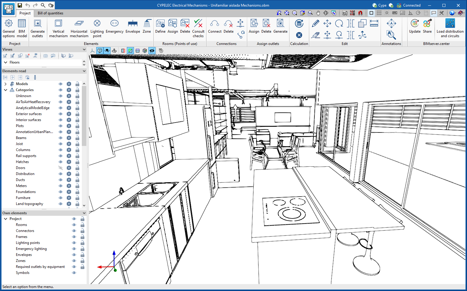
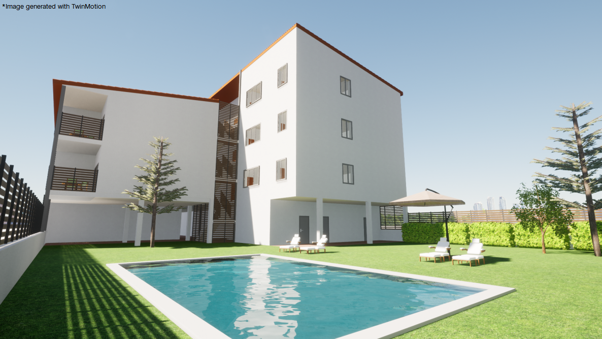
Version 2023.a of all CYPE programs that have the "Print/Save the current view" tool (usually all programs that display graphic information in a window) allows any generated 3D model to be exported in FBX format. This is one of the most common and accepted formats among rendering software (Twinmotion, Enscape, Sketchup+Vray, among others).
Exportation in FBX format is found in the dialogue box that opens when selecting the "Print/Save the Current View" button in any of the programs that include this tool. This feature allows users to export any element that is visible in the current window at that moment in FBX format (as well as elements that have been imported from other programs).
The drawing of contour lines has been improved. In the previous version of the application, the representation of contour lines could interfere with topographic surfaces when they were active.