Update history​​

CYPE Architecture

New tools and improvements have been included for intersection solutions:

  • Solve automatically
    This tool is equivalent to the "Intersection solution" tool from previous versions, but it has been improved by including new options for automatically solving intersections. It now allows greater control over the elements involved in the solutions. Users can choose whether to solve intersections between walls, between walls and floor slabs or on sloped roofs.
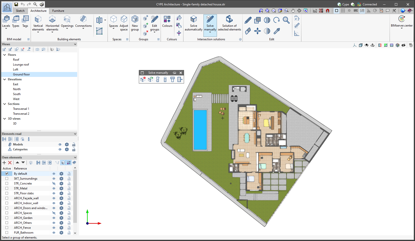
  • Solve manually
    A floating menu containing the tools for manually solving intersections (Delete, Regenerate, Cut by plane, Slice with surface, Subtract and Extend face) is opened. In previous versions, these were located directly within the "Intersection solution" group of tools.

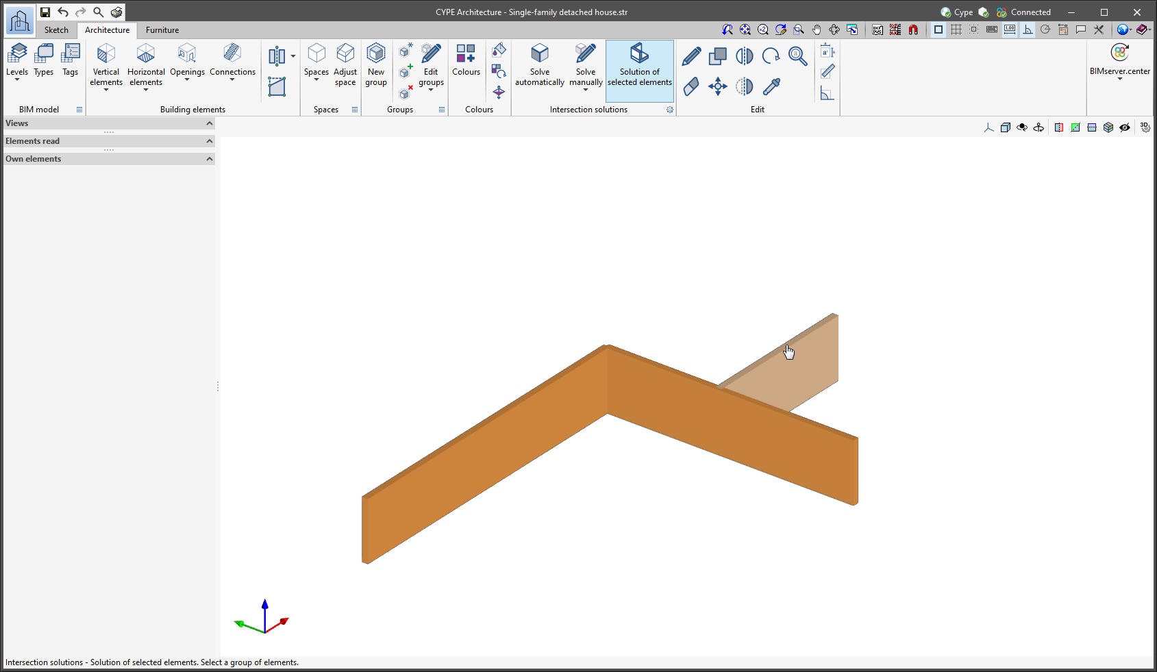
  • Solution of selected elements
    A new tool that allows users to solve intersections between walls, and between walls and floor slabs by previously selecting the elements for which the intersection is to be solved. This tool is of great use when a specific intersection has to be solved.

CYPE Architecture generates and exports different surface area tables. Surface area tables are generated from the floor areas of the spaces defined in the model. The surface area tables that are exported are as follows:

  • Complete surface area table with all the spaces of the job
  • Surface area table for each of the existing levels in the job
  • Surface area table for each of the existing groups in the job

Surface area tables are updated in Open BIM Layout when any change is made in CYPE Architecture that affects the spaces and is exported to the BIM project.

Since version 2022.a, the applications integrated within the Open BIM workflow via the BIMserver.center platform include a tool for managing project reference systems. This option is available from the configuration window that appears when linking or updating a BIMserver.center project via the "Geographic location and reference system" option. As of version 2023.d, the applications now allow users to run a graphical environment where they can visually define a reference system for their model. To do this, the "Geographic location and reference system" window now contains the "Visual editing of the local reference system of the model" option.

From the "Visual editing of the local reference system of the model" window, the origin and orientation of the reference system of the model can be indicated in the workspace with the "Define the reference system of the partial model" tool. Both the axes of the reference system of the model, which we have just entered and the axes of the reference system of the site can be viewed in the workspace. The latter appears with a "Site" tag.

To make it easier to define the reference system, the 3D models corresponding to the BIMserver.center project contributions selected during the linking process are displayed. The management of the visibility and object snaps of these models is carried out from the "Elements read" menu in the left sidebar of the window. The "Views" menu can also be found in the same options bar, from which different types of 2D and 3D views of the model can be generated. These tools can already be found in several CYPE applications. For more information on how they work, please refer to the User’s Manual for the 3D work environment tools available in CYPE applications.

Apart from 3D models, 2D drawings or plans can also be imported from CAD files (".dxf", ".dwg", ".dwf") or images (".jpeg", ".jpg", ".bmp", ".png", ".wmf", ".emf", ".pcx"). These files and object snaps are managed through the "DXF-DWG Template" and "Template object snaps" options accordingly.

Once the editing is complete, the coordinates and orientation of the reference system of the model with respect to the reference system of the site are moved to the corresponding fields in the "Geographic location and reference system" window.

The "Font size" option has been added to the general configuration menu of the applications. This tool allows users to increase or decrease the basic size of the font used in the user interface of the programs. Thanks to this implementation, the accessibility of the applications has been improved while also ensuring the correct visibility of the content on devices with different screen resolutions.

To enter a "Basic size" the "Set custom font size" option must be checked. The size users can enter is the application's basic font size. Any other font sizes that may exist in the program's interface will be automatically modified proportionally according to the change in the basic size.

It is important to note that, as this is a common parameter, its modification will affect all installed CYPE tools.

Version 2023.c includes new ceramic textures.

  • Custom-made showers
    The "Shower" feature allows users to enter custom-made showers, where they can choose the size of the shower, and the location of the shower screens and tap. With this new entry mode, the shower can be adapted to any space.

  • New furniture
    The library of furniture elements has been expanded. This time, outdoor furniture elements have been implemented, including children's playground equipment and sports fields and courts.

    The children's playground equipment includes swings, slides and see-saws. There is also a wide variety of sports fields and courts for athletics, tennis, padel, football, volleyball and basketball.

The tools in the "Beams" and "Columns" sections have a new entry mode: "Using sketch line". This entry mode allows the sketch lines to be selected in order to enter these elements. For columns, only completely vertical sketch lines can be selected.

This entry mode can be used to draw frame structures in a very simple way using the sketch lines, to then transform them into the architectural column and beam building elements that can later be reused for generating the structural model to be analysed in CYPECAD.

In previous versions of the program, only sketch surfaces and the lines forming the perimeter of the sketch surface could belong to a layer. However, sketch lines that did not form a surface could not be assigned to a layer, which made it difficult to model and manage sketch elements.

As of version 2023.c, any sketch lines shall be associated with layers, whether they belong to a surface or not.

  • Exporting DXF/DWG templates inserted by the user
    If users have entered DXF/DWG templates to model the job, these templates will be exported and stored in BIMserver.center and will be loaded into all other programs together with the 3D model.

  • Exporting groups of architectural elements and furniture to IFC
    Groups of architectural elements and furniture, defined using the "Groups" tool, are exported to the IFC standard via the "IfcGroup" entity. These groups can be read by other Open BIM applications such as Open BIM Quantities.

  • Interacting with Open BIM Layout
    • Updating tags and surface area tables
      Tags are updated in Open BIM Layout when program users update the BIM project data. Therefore, any change made in CYPE Architecture that affects these tags and is exported to the BIM project means that it will be updated in Open BIM Layout together with the project update.

Under the "Groups" section, users can access the groups table, which contains a list of the groups in the job, with instances of each type of group and the elements found in each of the instances.

In previous versions, elements in the "Architecture" and "Furniture" tabs could not be edited together. This meant that users could not edit (move, copy, rotate, etc.) elements from one tab and the other at the same time, which made editing very time-consuming.

Now, the "Edit" section of the "Architecture" and "Furniture" tabs has been unified, and users can edit elements from both tabs together, thus speeding up work significantly.

Since version 2020.f, applications with a 3D working environment include a floating toolbar to make it easier to enter or edit model components on the workspace. The options displayed in this toolbar depend on the active view and the element(s) being entered or edited.

This component is now anchored below the application toolbar. This makes better use of the available space in the user interface.