

The "Analysis" tab interface in the connection editor
Once you have finished defining the connection model in the "Model" tab, you can access the "Analysis" tab in the connection editor, where the connection is analysed and checked.
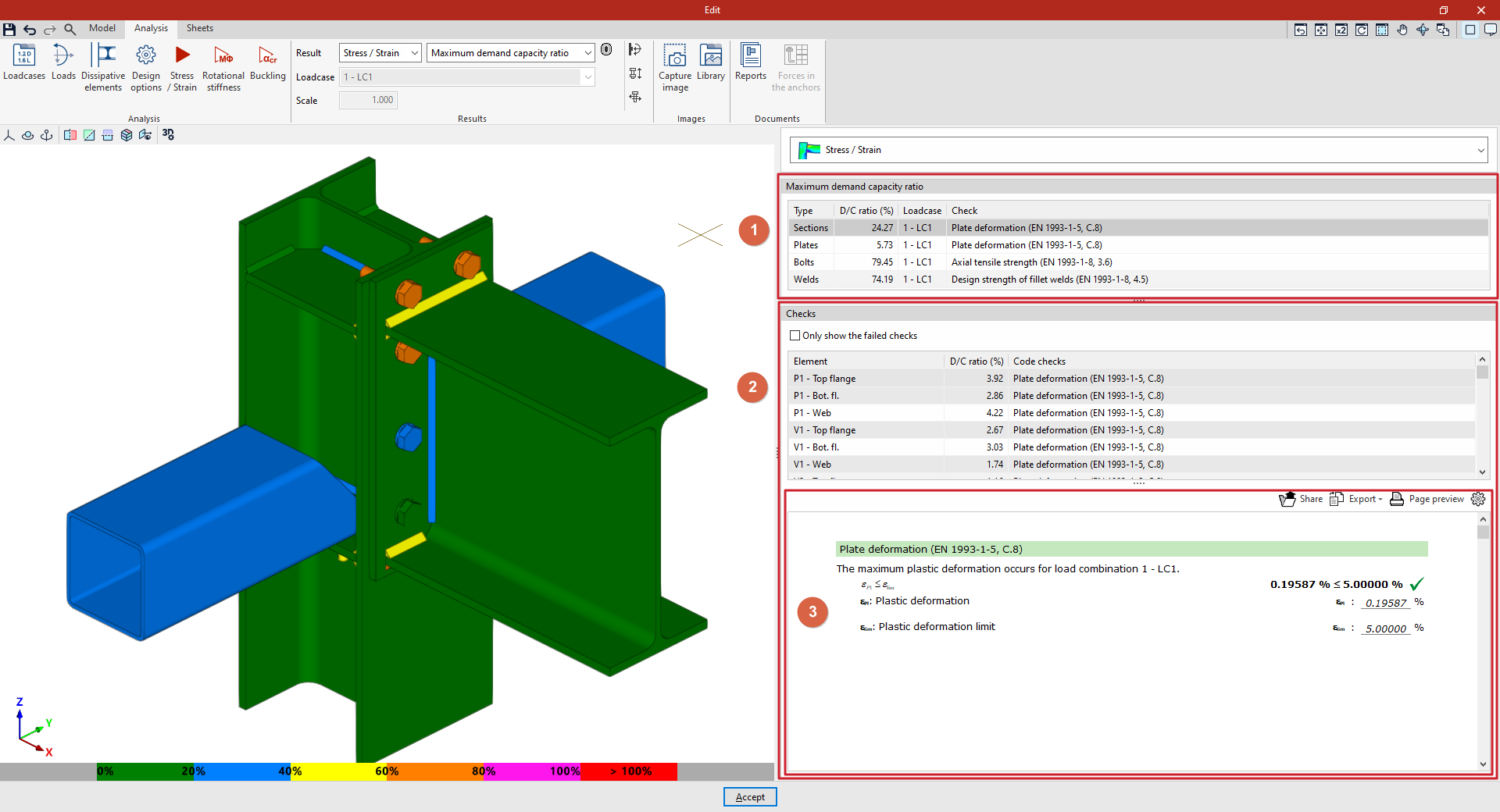
The interface on this tab displays the following areas:
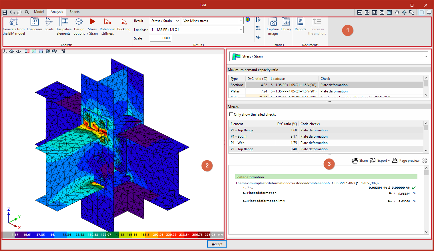
1. Top toolbar
- Define the "Load cases" to be considered, as well as the "Loads" applied to each section.
- Add them manually or generate them from a structural analysis model created using programs such as CYPECAD or CYPE 3D.
- Run the relevant analysis and checks by selecting:
- Stress / Strain
- Rotational stiffness
- Buckling
- View the "Results" using the drop-down menus, then go to the "Images" and "Document" sections associated with the connection.
2. Viewer (left)
View the model with colour coding based on the selected result. Depending on the type of result, you can also display the discretisation (mesh) used for the analysis.
3. Results tables (right)
View the summary tables for the analysis. For example, for "Stress / Strain", you can display:
- The "Maximum demand capacity ratio" of the connection's elements.
- The "Checks" carried out on these components.
Continuation of the workflow
Once you have finished modelling and performing the analysis, go to the "Sheets" tab to create the detailed drawings.
Generating loads and loadcases for connections from the BIM model
You can generate loads and loadcases automatically from the BIM model in CYPE Connect.
To do this, use the "Generate from the BIM model" option on the top toolbar of the "Analysis" tab within the connection editor. This option is available when the project has been created from a BIM model with internal forces (such as those from CYPECAD or CYPE 3D).

Generate from the BIM model
Clicking on the “Generate from the BIM model” option opens the “Read the loadcases from BIM model” window, which contains three sections: “Stress/Strain”, “Capacity design” and “Rotational stiffness”.
Stress / Strain
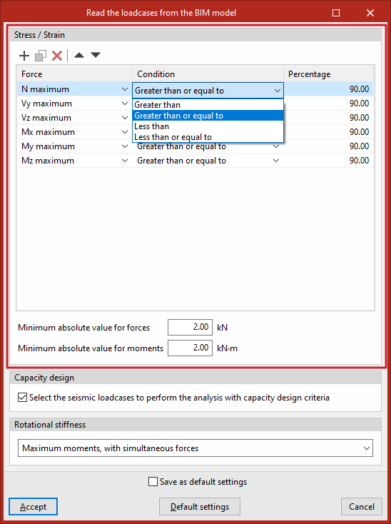
In the "Stress/Strain" section, the program can filter the load combinations to be imported from the BIM model for this calculation. Not all load combinations have significant values; therefore, it may be advisable to filter the number of combinations to be imported in order to reduce the calculation time.
To do this, filters are entered one by one into a table with the columns "Force", "Condition" and "Percentage".
By default, a filter is provided for each of the six types of "Force": axial (“N maximum”), shear forces in the Y and Z directions (“Vy maximum”, “Vz maximum”), and moments in the X, Y and Z directions (“Mx maximum”, “My maximum”, “Mz maximum”).
For each type of force, the combinations in which that particular force satisfies the selected "Condition" ("Greater than", "Greater than or equal to", "Less than" or "Less than or equal to") in relation to the specified "Percentage" of the maximum value, for both positive and negative values.
For example, you can specify the condition that the force must be "Greater than or equal to" 90 per cent of the maximum stress. This prevents loadcases with low force values from being imported.
In addition to filtering by percentage of effort, you can set a minimum value to determine whether or not to include the combinations by entering an "Absolute minimum value for forces" and an "Absolute minimum value for moments" in the boxes at the bottom of this section.
Design by capacity
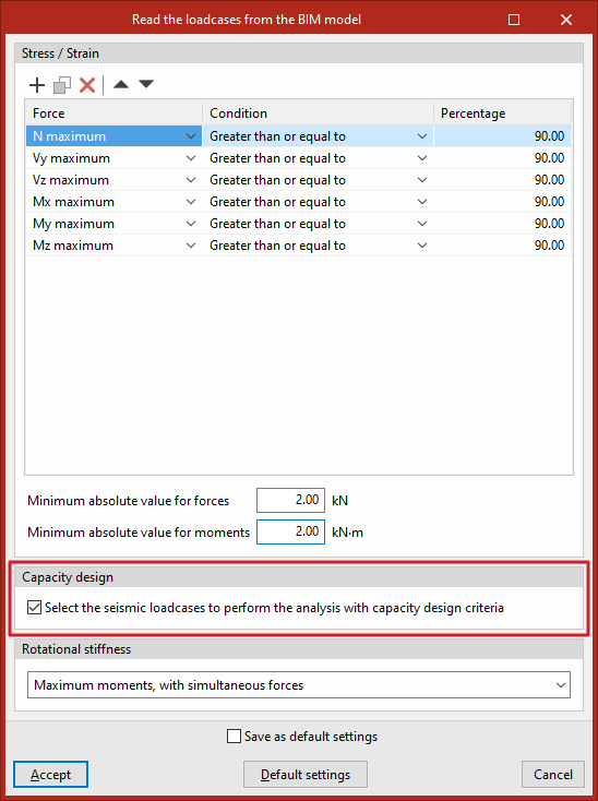
In the "Capacity design" section, you can tick the relevant box to "Select the seismic loadcases to perform the analysis with capacity design criteria".
The program will therefore identify loadcases of this type and automatically tick the "Capacity design" box for them in the list of loadcases.
Rotational stiffness
The "Generate from BIM model" option can also be used to import loads for rotational stiffness analysis. In addition to the loads, the elastic lengths of the bars in the structural model are also imported; these lengths are required for the correct classification of the connection.
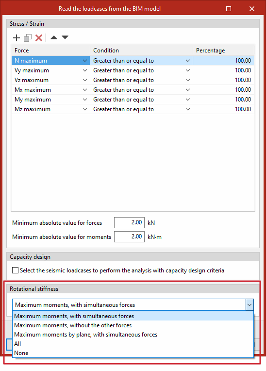
From the drop-down menu in the "Rotational stiffness" section, select one of the following five options to import the loadcases based on the internal forces:
- Maximum moments, with simultaneous forces
Enter the loadcases with the highest moments "My" or "Mz", with a positive or negative sign, as well as the other associated stresses. - Maximum moments, without the other forces
For loadcases involving peak moments, only the values of "My" and "Mz" are relevant. - Maximum moments per plane, with their corresponding
forces
Import the loadcases corresponding to the maximum bending moments, together with their associated force components, by plane (i.e. the XY and XZ planes). - All
Import all loadcases. - None
Does not import any loadcases.
After clicking "Accept", the "Loadcases" and "Loads" for the sections involved in the connection are generated based on the defined configuration.
From here, you can click on the relevant buttons on the top toolbar to view the information generated in both sections or to make changes if required.
Defining loadcases in the connection editor
To configure loadcases in the program, use the "Loadcases" option on the top toolbar of the "Analysis" tab within the connection editor.

Loadcases
The window that appears when you click this option is used to define the loadcases that can be taken into account in the connection analysis.
Generating or entering loadcases
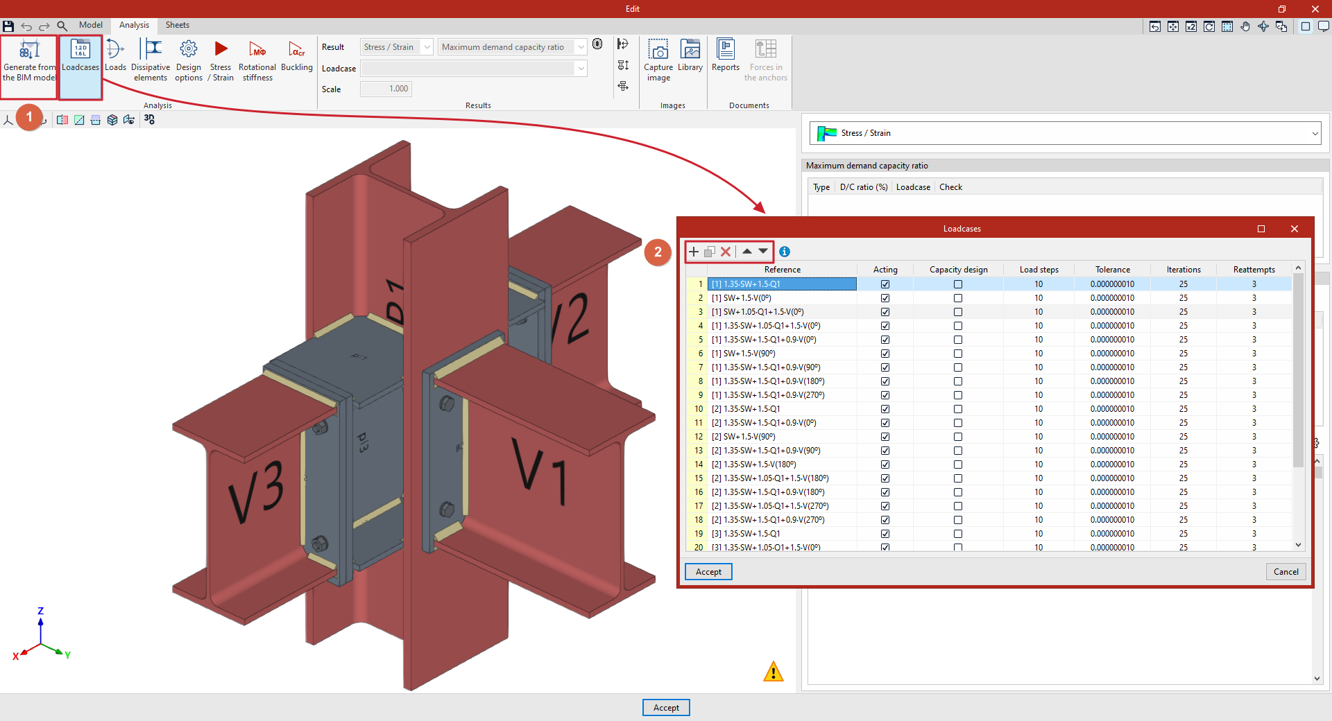
Loadcases may have been generated automatically using the "Generate from the BIM model" option (1), located on the top toolbar of the "Analysis" tab interface.
You can also edit or enter them manually. In that case, you use the buttons at the top of the table (2), which allow you to "Add", "Copy", "Delete" and move loadcases within the list.
Defining loadcases
The following parameters are defined for each loadcase:
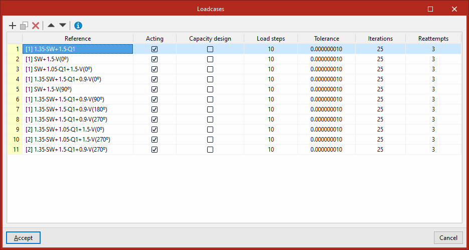
- First, enter the "Reference" for the loadcase.
- Next, you indicate whether or not the loadcase is "Acting" in the analysis by ticking the relevant box.
- To analyse the connection taking into account the safety factor in dissipative elements, tick the "Capacity design" box for loadcases of this type in the list (in addition, "Dissipative elements" must be selected using the corresponding option on the top toolbar of the "Analysis" tab interface). The material properties of the dissipative elements are adjusted for the selected loadcases, taking into account the effects of the material’s over-resistance.
On the right are the configuration parameters for the non-linear analysis of the connection carried out by the program using the OpenSees engine. Material, geometric and contact non-linearities can cause changes to the stiffness matrix. For this reason, the analysis process is incremental and iterative:
- Loadsteps
The loads applied in each load case are divided by the number of "Load steps" indicated in this column, and are applied incrementally at each step until 100 per cent of the loads is reached.
For example, if a load of 100 kilonewtons is applied and 5 steps are defined, each load step will add a further 20 kilonewtons until the total reaches 100.
The values in the following columns, "Tolerance" and "Iterations", are associated with each load step.
- Tolerance
In this column, you must enter the permitted "Tolerance" for determining that convergence has been achieved.
The convergence criterion used to terminate the iterative process at each loading step is the energy error.
When the change in energy between one iteration and the previous one is less than the defined tolerance, the program considers that equilibrium has been reached at that loading step and moves on to the next one.
- Iterations
This column shows the maximum number of "Iterations" to be carried out at each load step.
- Retry attempts
If equilibrium is not reached at any step within the maximum number of iterations entered, the analysis is restarted by doubling the number of load steps.
If equilibrium is still not reached, this process is repeated and is terminated if the maximum number of "Retry attempts" entered in this column is reached.
The default values in the program are considered optimal for achieving good results within a reasonable analysis time.
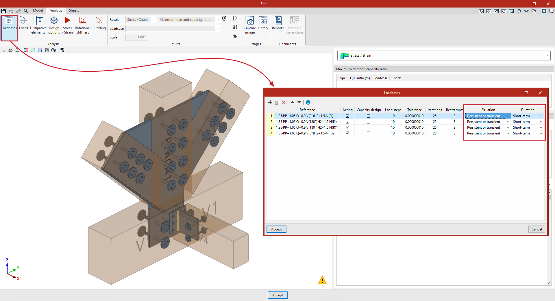
Finally, if the connection includes timber sections, the "Condition" and "Duration" for each loadcase are also selected from the relevant drop-down menus.
Entering loads in the connection editor
To enter loads on the bars in the program, click on the "Loads" option in the top toolbar of the "Analysis" tab within the connection editor.

Loads
The "Loads" option is used to define the loads applied to the bars in the connection for each loadcase.
The loads may have been generated automatically using the "Generate from BIM model" option.
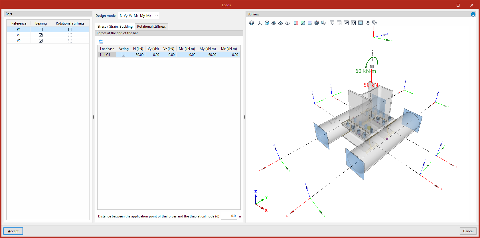
You can edit them or enter them manually. In that case, select each of the "Bars" in the table on the left, which shows their "Reference", as well as the "Load-bearing" and/or "Rotational stiffness" columns, where applicable.
Selecting load-bearing beams
In the connection analysis model, you must define one or more bars of the connection as "Load-bearing" by ticking the corresponding box in the column of the same name, unless an baseplate has been defined (in these connections, no bars may be designated as load-bearing, and this column will not be displayed).
The remaining bars are connected to this component, to which the loads are applied.
Each load-bearing beam has an external connection at one end. If the load-bearing bar is continuous or runs through the connection, you must specify whether there is an "External connection" "At both ends", "At the start end" or "At the final end" of the section by selecting one of the options from the drop-down menu that will appear in the centre of the dialog box.
The program displays a message stating that "The forces do not need to be entered into the load-bearing section, as they are determined by equilibrium".
Selecting the design model
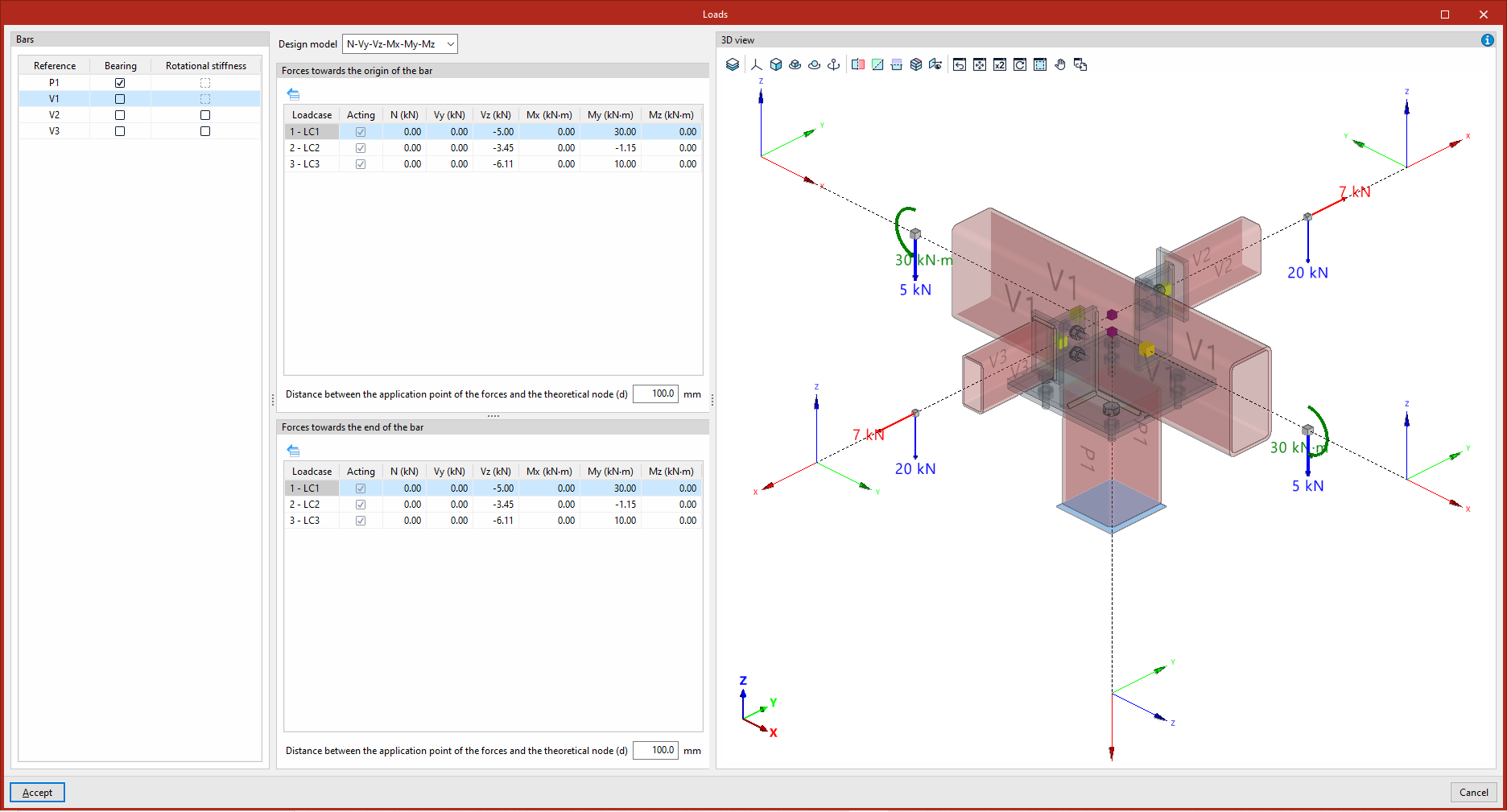
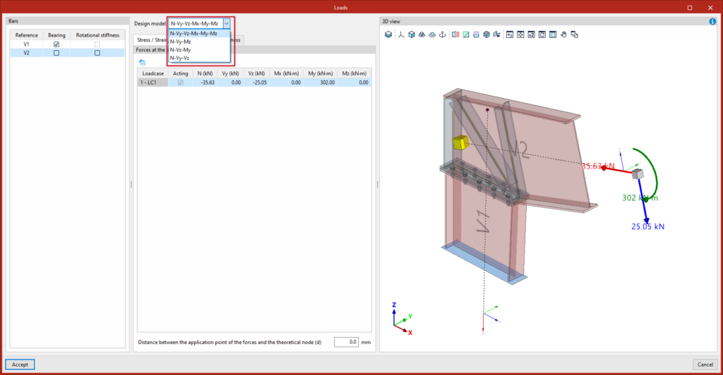
Each non-load-bearing bar includes the "Design model" drop-down menu, which allows you to select different load and constraint configurations, better suited to various structural situations. You must select one of the following options:
- N – Vy – Vz – Mx – My – Mz
This is the default model. The end of the beam has no external connections, allowing the six internal forces to be defined: the axial force, the shear forces in the Y and Z directions, and the moments in the X, Y and Z directions. - N - Vy - Mz
This model allows loads to be defined in the XY plane. The end of the beam is constrained against displacement along the z-axis and rotation about the y-axis. The axial force, the shear force in the Y-direction and the moment in the Z-direction are defined. - N - Vz - My
This model allows loads to be defined in the XZ plane. The end of the beam is constrained against displacement along the y-axis and rotation about the z-axis. The axial force, the shear force in the Z-direction and the moment in the Y-direction are defined. - N - Vy - Vz
In this model, the end of the bar has its rotational degrees of freedom restrained, while no moments can be applied. The axial force and the shear forces in the Y and Z directions are defined.
In the central part of the dialog box, below this drop-down menu, there are two tabs for defining the load or force tables in the units specified for each "Loadcase" (indicating whether it is "Acting" or not). Right-clicking on the cells brings up additional tools that allow you to copy and paste data directly from spreadsheets.
In the design model, the program will apply loads at the end of each section to calculate the forces entered by the user at the specified point.
"Stress/Strain, Buckling" tab
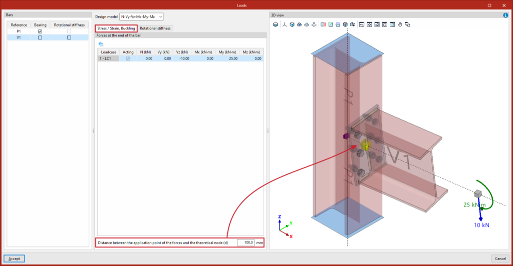
In the "Stress/Strain, Buckling" tab, the loads or "Forces at the end of the bar" are defined for each load case to carry out these analyses (and the "Forces towards the origin of the bar" if the bar is continuous or passes through the connection), by entering their values in the cells of the central table.
In the field below each internal force table, you can also enter the “Distance between the point of application of the forces and the theoretical node”. This allows you to specify where the forces are being defined on each bar:
- If the forces at the theoretical node – that is, the point where the section axes intersect – are being entered, the distance value must be zero.
- If you wish to input forces from another point – for example, those acting on the face of a column – you must enter a distance value equal to half the width of that column.
This distance will also be read from the BIM model, provided that the structure has been analysed considering the finite dimensions of the connections.
'Rotational Stiffness' tab
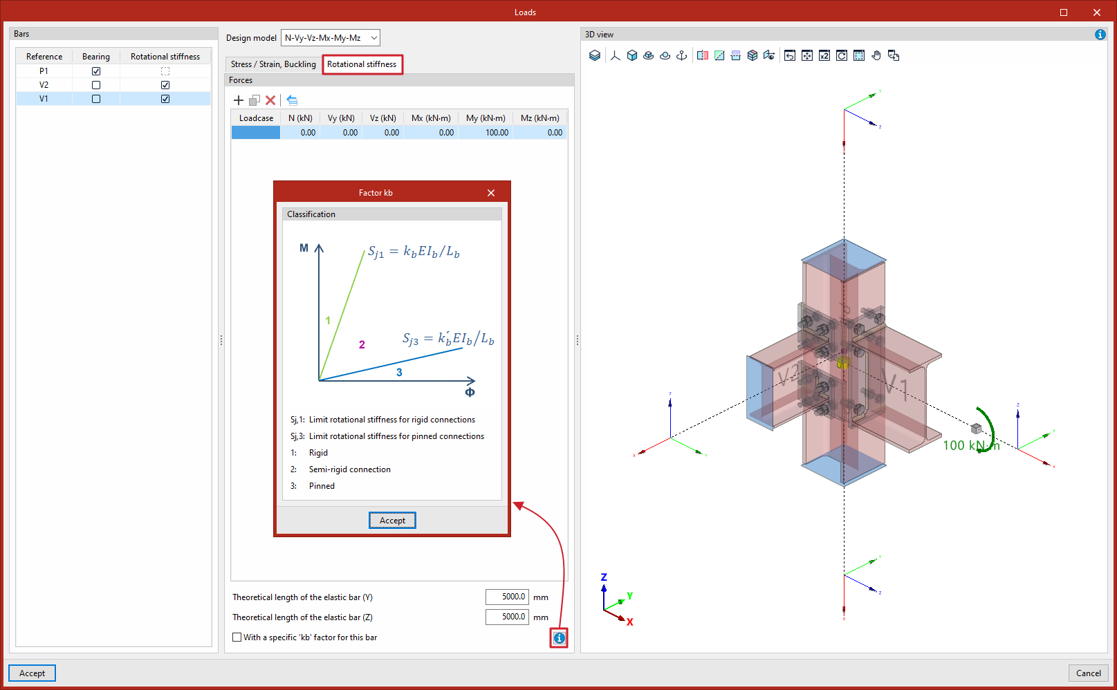
In the "Bars" browser on the left, you can also select the bars for which you wish to calculate the rotational stiffness of the connection by ticking the "Rotational stiffness" box in the relevant column.
The "Rotational stiffness" tab requires a list of loads or "Forces" for each loadcase, which can be entered into the cells in the central table.
In addition, at the bottom, you must enter the lengths of the elastic bar in the structural model (used to determine the limit stiffnesses of rigid or hinged connections) and the kb factor:
- Theoretical length of the elastic rod (Y)
- Theoretical length of the elastic rod (Z)
- With a "kb" factor specific to this bar (optional)
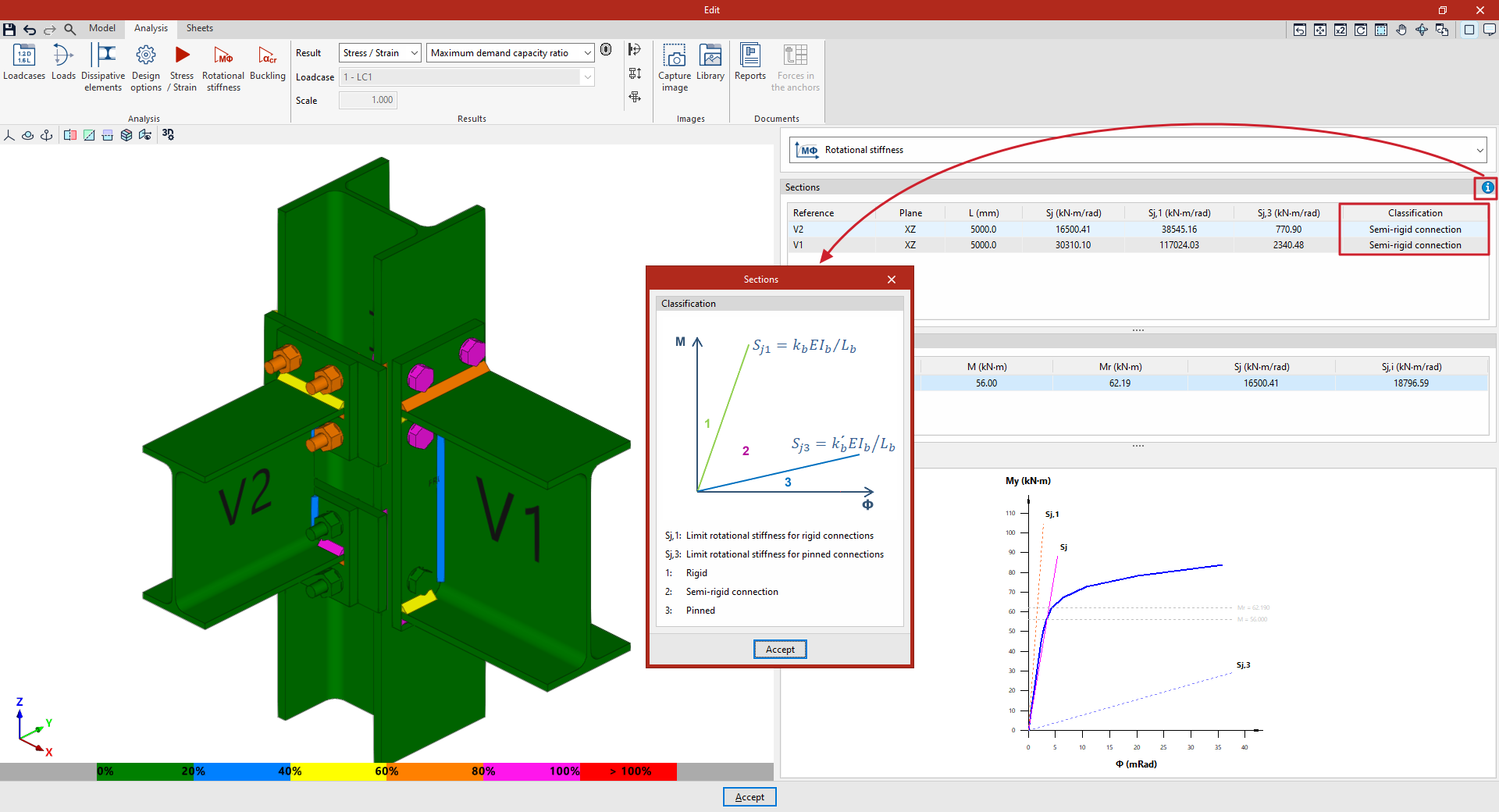
The diagram, which can be accessed via the help button at the bottom, shows how the connection is ‘classified’ as "Rigid" (1), "Semi-rigid" (2) or "Hinged" (3) in the M-Φ plane, based on the definition of the "Limit rotational stiffness for rigid connections", Sj1=kbEIb/Lb, and the "Limit rotational stiffness for pinned connections", Sj3=k'bEIb/Lb.
"Buckling" tab
This tab appears only if the “Perform the instability analysis with the same loads as the Stress/Strain analysis” option has been deselected in the “Analysis options” and allows you to enter the internal forces specifically for the buckling analysis.
Editing forces
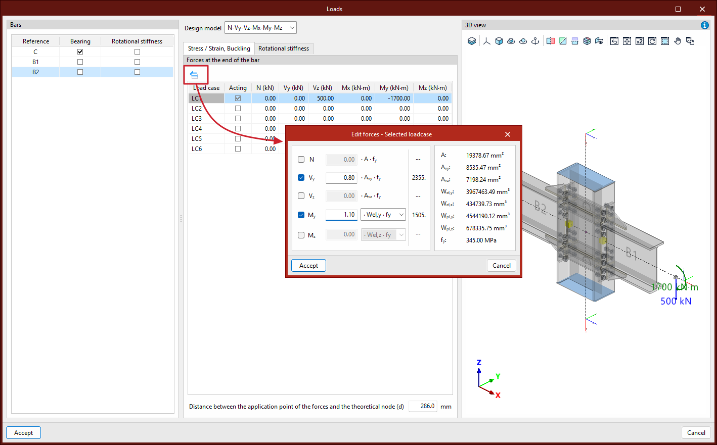
The "Edit forces – Selected loadcase" tool, which is common to both tabs, allows you to define the forces applied to each bar based on its mechanical properties:
- The "N" axis is defined by entering a coefficient that multiplies the product A·fy.
- The "Vy" cutting factor is defined by entering a coefficient that multiplies the product Avy·fy.
- The "Vz" shear force is defined by entering a coefficient that multiplies the product Avz·fy.
- The "My" moment is defined by entering a coefficient that multiplies the product Wel,y·fy, or alternatively Wpl,y·fy.
- The "Mz" moment is defined by entering a coefficient that multiplies the product Wel,z·fy, or alternatively Wpl,z·fy.
- On the right, the values of the mechanical properties A, Avy, Avz, Wel,y, Wpl,y, Wel,z, Wpl,z and fy for the bar are shown.
For example, this feature makes it easier to design connections with a higher strength than that of the joined bars – a common requirement in various seismic design codes.
3D view
In the "3D view" on the right-hand side of the dialog box, the loads applied to each bar in the connection are displayed graphically according to the selected loadcase.
The theoretical node and the point at which the forces are applied are also shown as a yellow cube, cylinder or sphere (depending on the calculation model chosen).
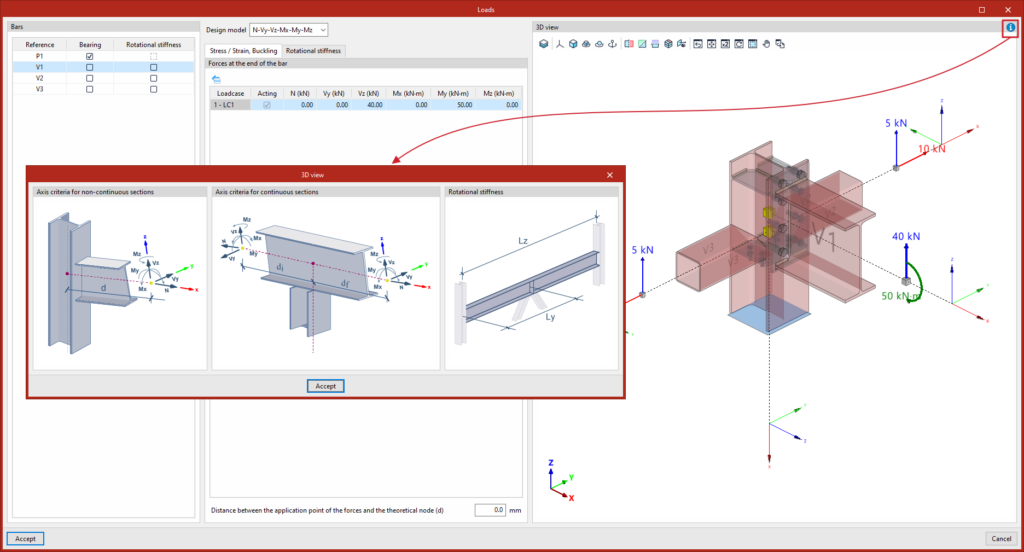
In addition, the help button in the top right-hand corner opens a diagram showing the “Axis criteria for continuous sections” and the “Axis criteria for non-continuous sections” (which allows you to determine the direction and sense of the forces applied with a positive sign), as well as the parameters relating to the ‘Rotational stiffness’ analysis (Ly and Lz).
To apply the changes, click “Accept”.
Design options in the connection editor
To configure the design options for each joint in the program, use the following option on the top toolbar of the "Analysis" tab within the connection editor.

Design options
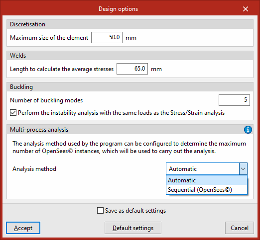
This tool allows you to configure the “Design options”.
Firstly, in the "Discretisation" section, enter the "Maximum element size". This value refers to the side length of the triangular finite elements used by the program to discretise the sections and plates. Using a value between 30 and 50 millimetres yields good results with reasonable calculation times.
Next, in the "Welds" section, you can adjust the "Length for calculating average stresses". Stress concentrations typically occur at the ends of the weld bead, where the values are usually higher than elsewhere. If this is the case, increasing the length reduces the average stress.
In the “Buckling” section, you can select the “Number of buckling modes” to be calculated in this analysis. The buckling analysis can be carried out using the same loads as the "Stress/Strain" analysis or using a different set of loads. This can be controlled by ticking or unticking the "Perform the instability analysis with the same loads as the Stress/Strain analysis". If this option is enabled, the “Buckling” tab will appear in the “Loads” dialogue box, where you can enter the internal forces specifically for this calculation.
In the "Multiprocessing" section, you can configure the "Analysis method" used by the program to determine the maximum number of OpenSees© engine instances to be used to carry out the analysis. The "Automatic" method aims to make the most of the computer’s capacity by launching as many instances as possible, whilst if "Sequential" is selected, you must enter the "Maximum number of OpenSees© instances". Further information on these methods can be found by clicking on the help button on the right-hand side.
To confirm the changes, click on "Accept".
Stress–strain analysis in the connection editor
The following option in the top toolbar of the "Analysis" tab, within the connection editor, allows you to carry out the stress–strain analysis for each connection:

First, configure the "Loadcases" and the "Loads" acting on each section using the options in the top toolbar. These may have been generated automatically using the “Generate from BIM model” option.
Stress / Strain
The "Stress/Strain" option allows you to carry out the stress analysis and verify the connection elements.
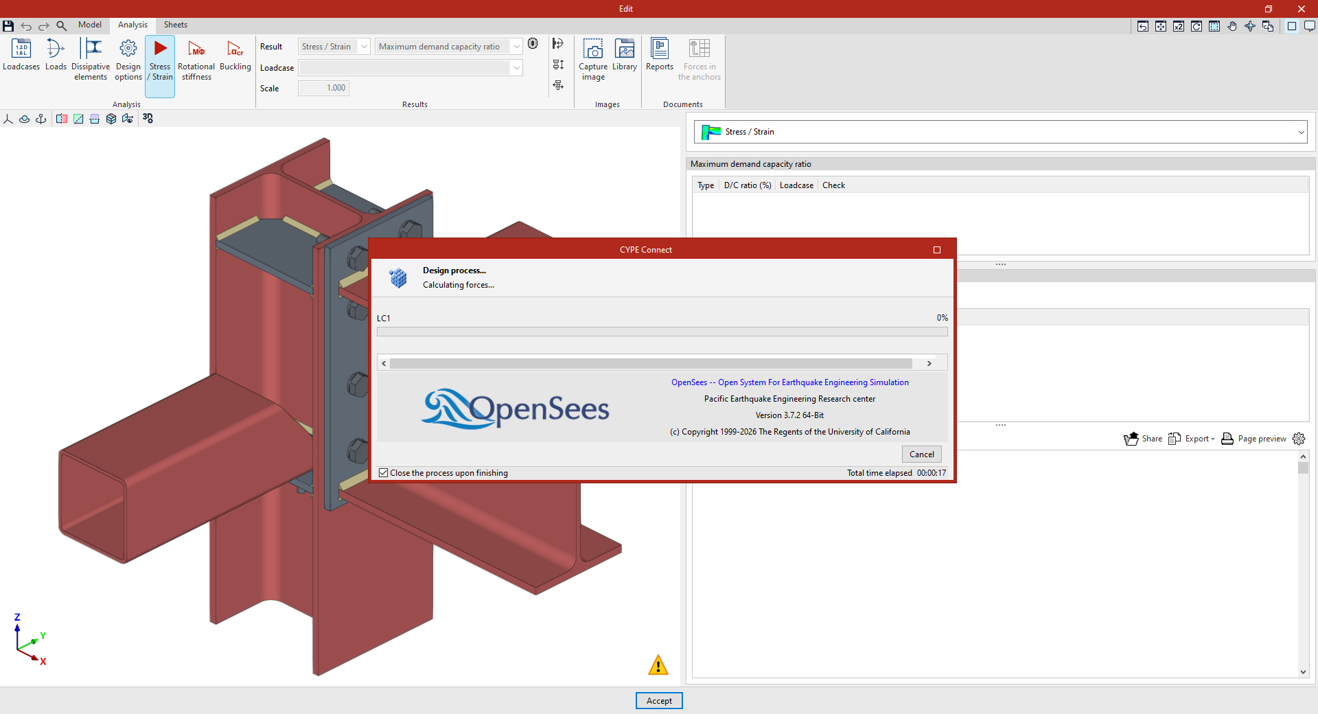
The first time the analysis is run, the deployed version of OpenSees© is automatically installed. If it is already installed, the analysis is carried out. If multiple processors are available, the program can analyse several loadcases simultaneously.

Once you have finished, you can view the results provided by the program to continue your work.
Viewing stress/strain analysis results in the connection editor
You can view the results after carrying out the connection analysis in the program by using the options in the "Results" section of the top toolbar on the "Analysis" tab within the connection editor.

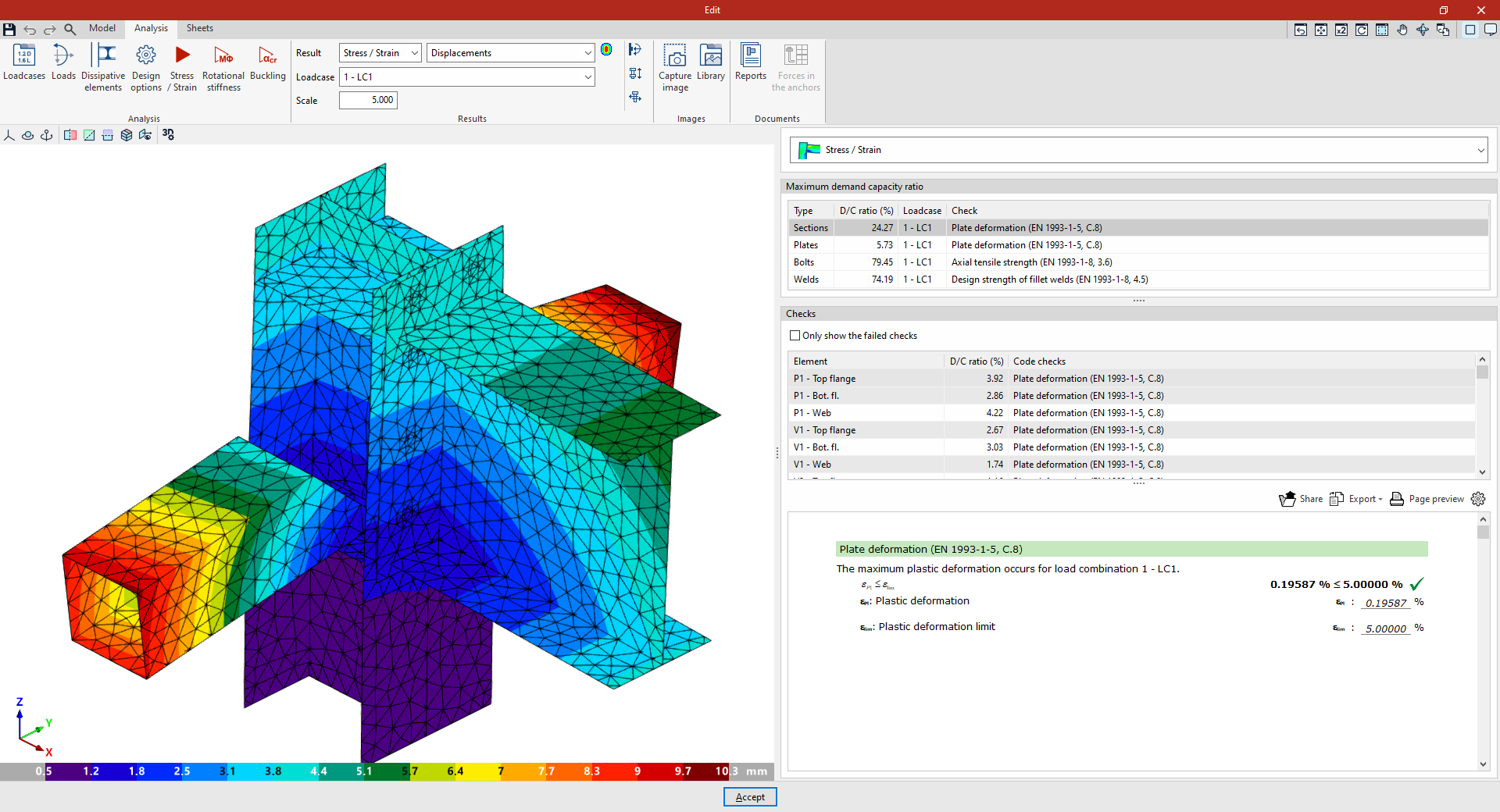
In the "Result" drop-down menu, you can select "Stress / Strain" and then, in the second drop-down menu, one of the following options:
- Maximum demand capacity ratio
- Von Mises stress
- Equivalent Von Mises deformation
- Displacements
Each of these is explained below:
Maximum demand capacity ratio
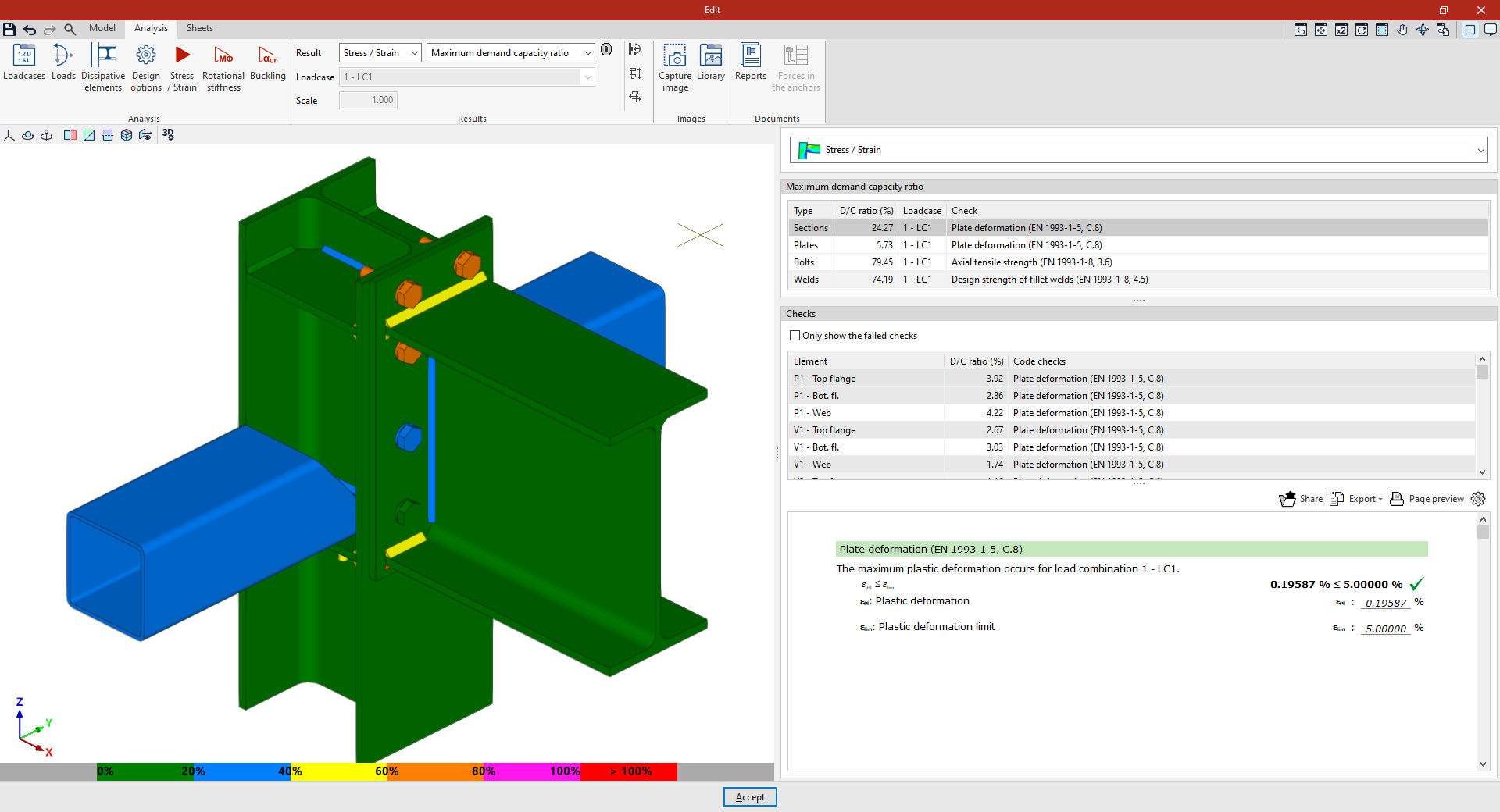
If "Maximum demand capacity ratio" is selected, in the 3D view of the connection on the left-hand side of the window, each element is displayed in a colour corresponding to its demand capacity ratio.
A colour scale is displayed at the bottom of the 3D view of the connection to aid interpretation
The following results are also displayed on the right-hand side of the window when you select "Stress / Strain" from the drop-down menu:
Maximum demand capacity ratios
At the top of the right-hand side there is a table (1) showing the "→ Maximum demand capacity ratios" of the components for each "Type", including "Sections", "Plates", "Bolts" and "Welds".
Each of them shows the maximum "Demand capacity ratio" percentage and specifies the "Loadcase" and "Verification" to which it corresponds.
Checks
Below this is the "Checks" table (2) for each connection component, based on the various criteria set out in the standards selected by the user. If desired, the "Only show the failed checks" box can be ticked.
Here, for each "Element" in the connection, the "Demand capacity ratio" percentage is shown in the corresponding "Check".
The results displayed on the screen and on the side panel are coordinated as follows:
- If you click on a connection element in the viewport, the table will display only the checks for the selected element.
- If you click on an empty space in the 3D view, the checks for all the elements in the connection are displayed.
Furthermore, when you select an element "Type" in the "Maximum loads" table, the program selects the corresponding element in the "Checks" table.
Detailed check report
When you click on any check, the program displays a detailed report of that check (3) in the bottom right-hand corner, showing the relevant section of the regulations and the parameters involved in its verification.
This information can be "Shared" or "Exported" in various formats or printed directly from the "Preview".
| Note: |
|---|
| For "Sections" and "Plates", deformation is tested, with the plastic deformation limit set at 5 per cent. For "Bolts", the distances to the edge and between bolts, tensile strength, shear strength and crushing strength, and the interaction between shear and tensile forces are tested. For prestressed bolts, slip resistance is also checked. For “Welds”, the strength of fillet welds and partial penetration welds is checked, in accordance with the applicable standard. For full-penetration welds, their strength is considered to be greater than that of the elements they join, in accordance with the standards taken into account by the program. |
Von Mises stress
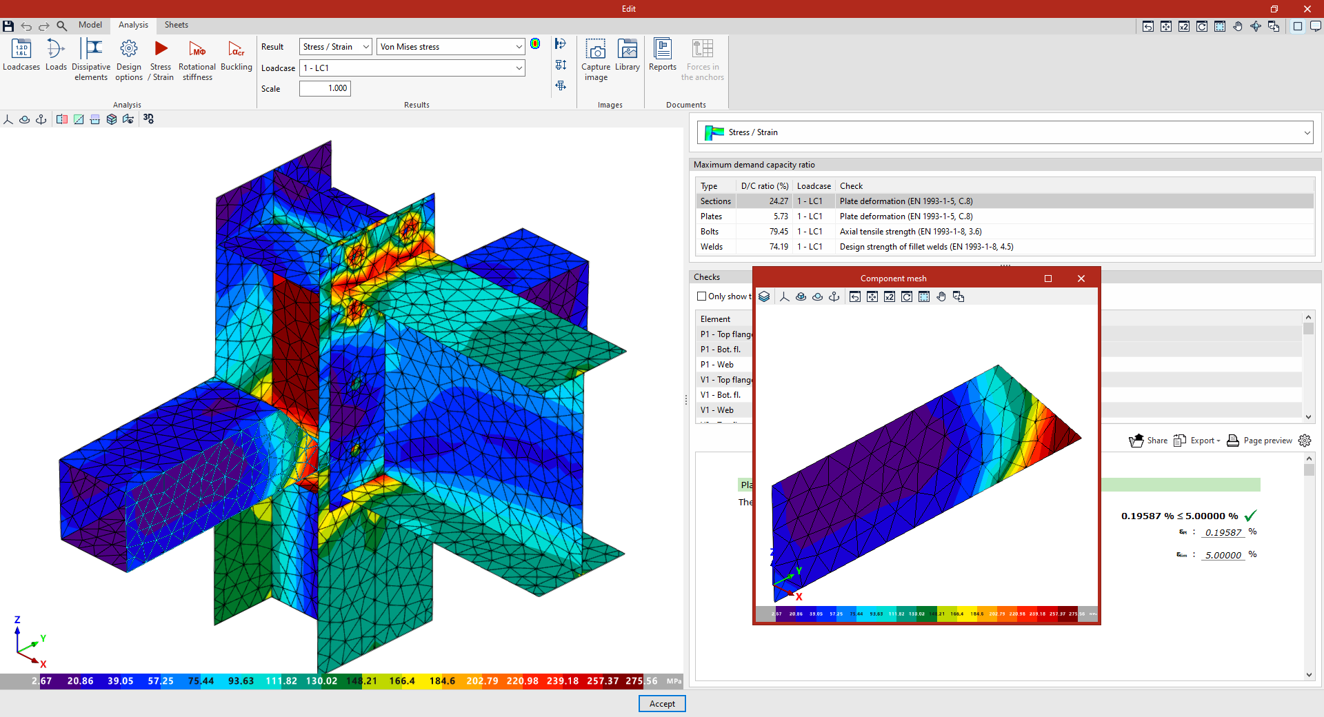
By selecting the relevant option from the "Result" drop-down menu on the top toolbar, you can also view the "Von Mises stress" for the selected "Loadcase"
As a result, in the connection view, the contour plot of the selected von Mises stress and the element discretisation are displayed.
You can also click on any sheet to bring up a pop-up window showing the "Component mesh" and the results for that specific sheet.
Equivalent Von Mises deformation
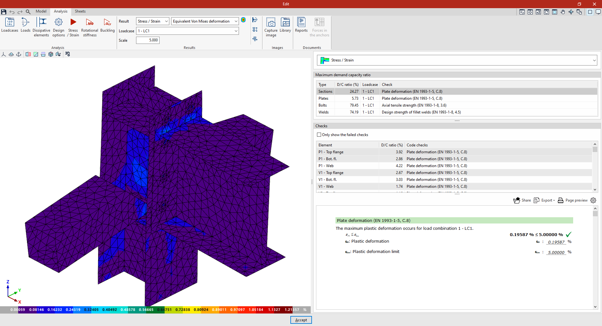
The next result that can be selected is the contour plots for the "Equivalent Von Mises deformation".
Once again, for each "Loadcase", the program plots the percentage values of the deformation using contour plots.
Displacements
Finally, the "Displacements" values for the connection elements can be displayed via their representation in the 3D view by selecting the relevant "Loadcase".
You can apply a "Scale" to the displacements by entering a value in the relevant field in the "Results" group on the top toolbar to improve their display.
Display options
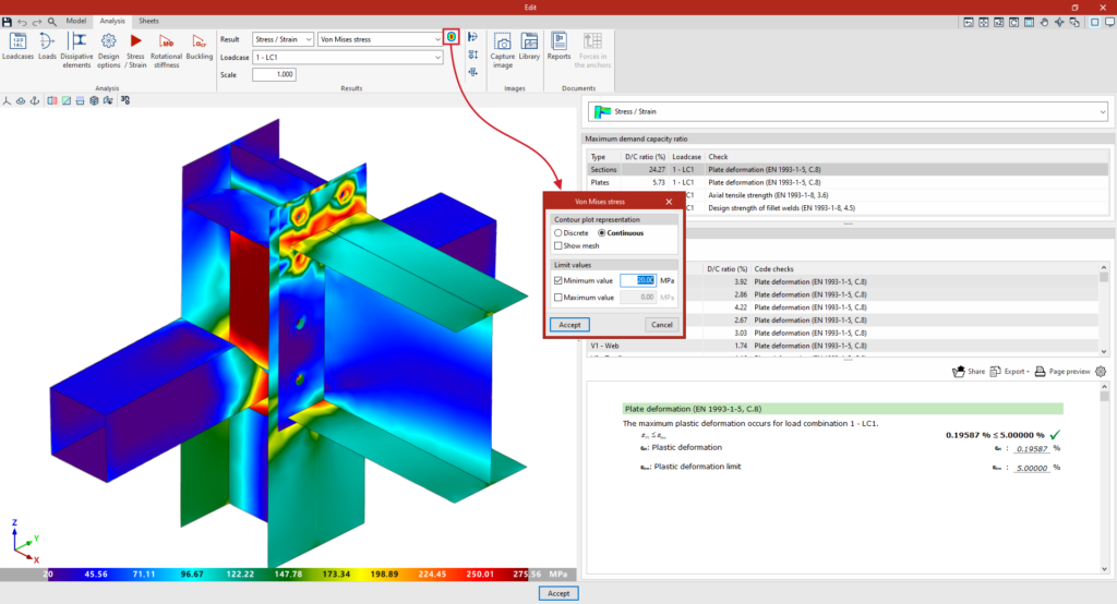
To the right of the "Results" drop-down menu, you can configure the "Display options" to adjust the result views by contour plots:
- The "Contour plot representation" can be "Discrete" if you want the program to use a finite colour scale, or “Continuous” if you want it to use a gradient.
- The "Show mesh" option is also included, which allows you to show or hide the finite element mesh by toggling it on or off.
- In addition, "Limit values" can be specified for the display of results by adjusting both the "Minimum value" and the "Maximum value" of the scale.
Analysing rotational stiffness in the connection editor
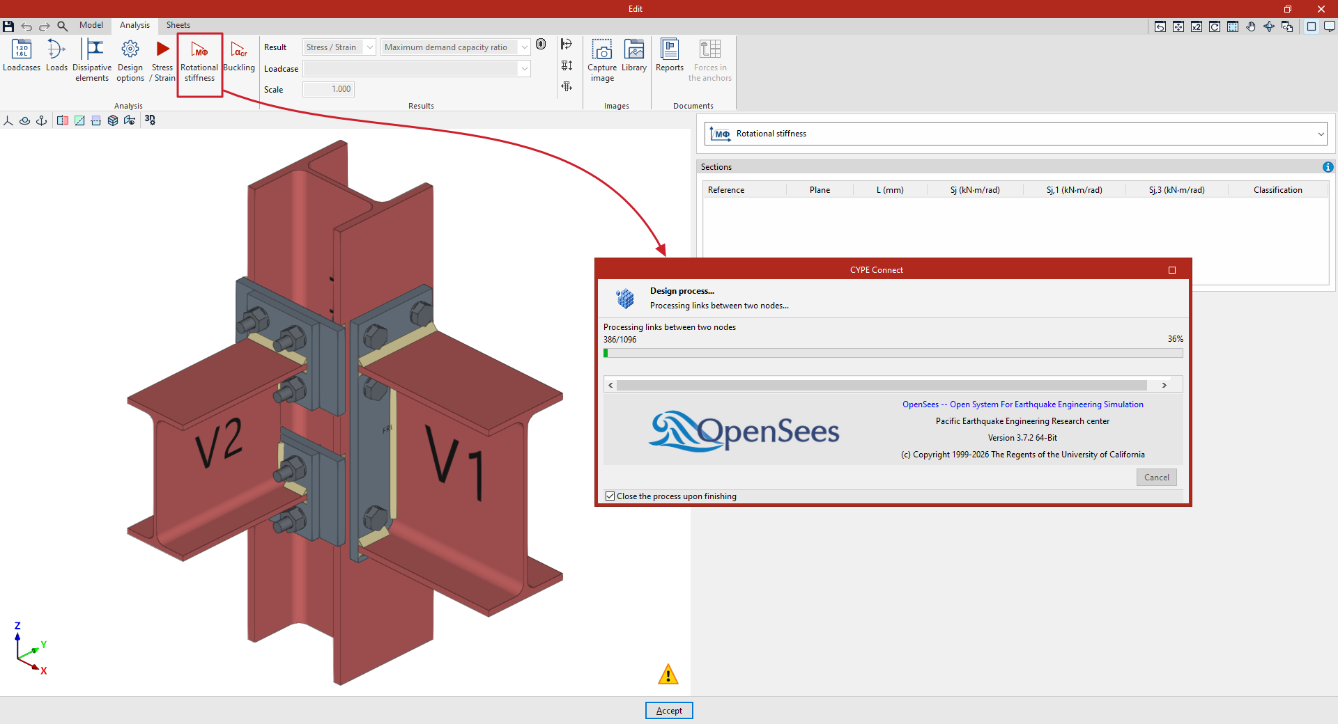
The following option in the top toolbar of the "Analysis" tab, within the connection editor, allows you to carry out a rotational stiffness analysis for each connection:

First, configure the "Loadcases" and the "Loads" acting on each bar using the options in the top toolbar. In the "Loads" panel, select the bars for which you wish to carry out the “Rotational stiffness” analysis and enter the internal forces, the elastic lengths of the bars in the structural model and the kb factor.
The loads, the elastic lengths of the bars in the structural model and the load cases may have been generated automatically using the "Generate from BIM model" option. The import of loadcases for rotational stiffness analysis can be configured in the "Rotational stiffness" section of the window that appears when you click on this option.
Rotational stiffness
The "Rotational stiffness" option carries out the rotational stiffness analysis. This design option allows you to determine the moment capacity, initial stiffness, secant stiffness and connection classification (rigid, semi-rigid or pinned) of steel sections.
To obtain the moment-rotation diagram, the program carries out an iterative process, calculating the rotation at different load steps. The resisting moment is obtained when any component of the connection (plates, sections, welds or bolts) fails, i.e. when its demand capacity ratio exceeds 100 per cent.
Once you have finished, you can view the results provided by the program to continue your work.
Viewing the results of the rotational stiffness analysis in the connection editor
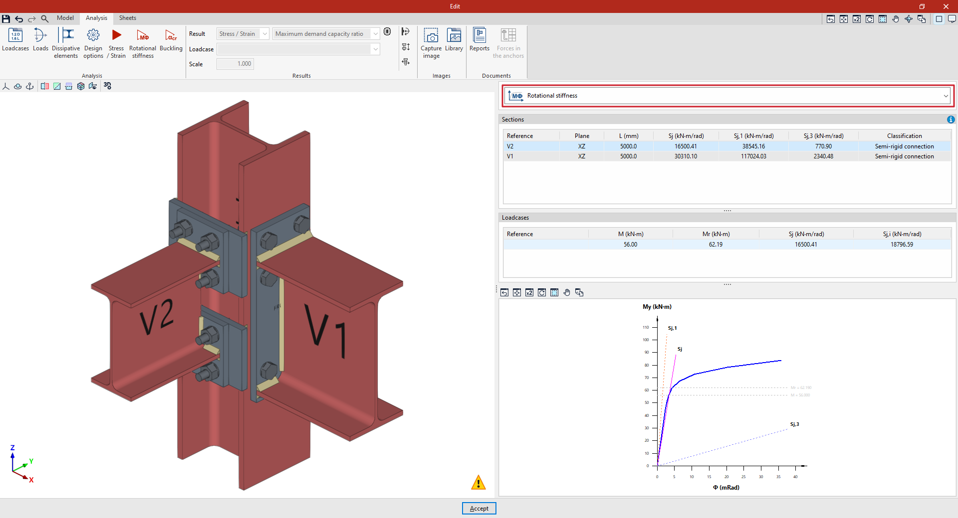
The results of the rotational stiffness analysis are displayed on the right-hand side of the "Analysis" tab, within the connection editor.
From the drop-down menu at the top, you can select the type of results to be displayed. When you select "Rotational stiffness" from this drop-down menu, the program displays two tables and the moment-rotation diagram:
"Sections" table
The first table shows all the analysed bars with their "Reference", "Plane", "Length", secant stiffness ("Sj"), the limit rotational stiffness for rigid connections ("S,j1"), the limit rotational stiffness for pinned connections ("Sj,3") and the classification of the connection in each plane ("Rigid", "Semi-rigid" or "Pinned").
To classify a connection as rigid, semi-rigid or hinged, the limit stiffness values for rigid and hinged connections must first be established. Depending on the selected steel standard, either the initial stiffness or the secant stiffness will be compared with these limits.
"Loadcases" table
This table shows the load cases calculated for the selected member. Each load case indicates the applied moment ("M"), the resisting moment ("Mr"), the secant stiffness ("Sj") and the initial stiffness ("Sj,i").
Moment-rotation (M-Φ) graph
The graph shows the moment-rotation curve, the applied moment for the selected loadcase (M), the resisting moment (Mr), the secant stiffness (Sj), the limit stiffness for rigid connections (Sj,1) and the limit stiffness for hinged connections (Sj,3).
The diagram, which can be accessed via the help button in the top right-hand corner, shows the "Classification" of the connection as "Rigid" (1), "Semi-rigid" (2) or "Hinged" (3) in the M-Φ plane, based on the definition of the "Limit rotational stiffness for rigid joints", Sj1=kbEIb/Lb, and the "Limit rotational stiffness for hinged joints", Sj3=k'bEIb/Lb.
Buckling analysis in the connection editor
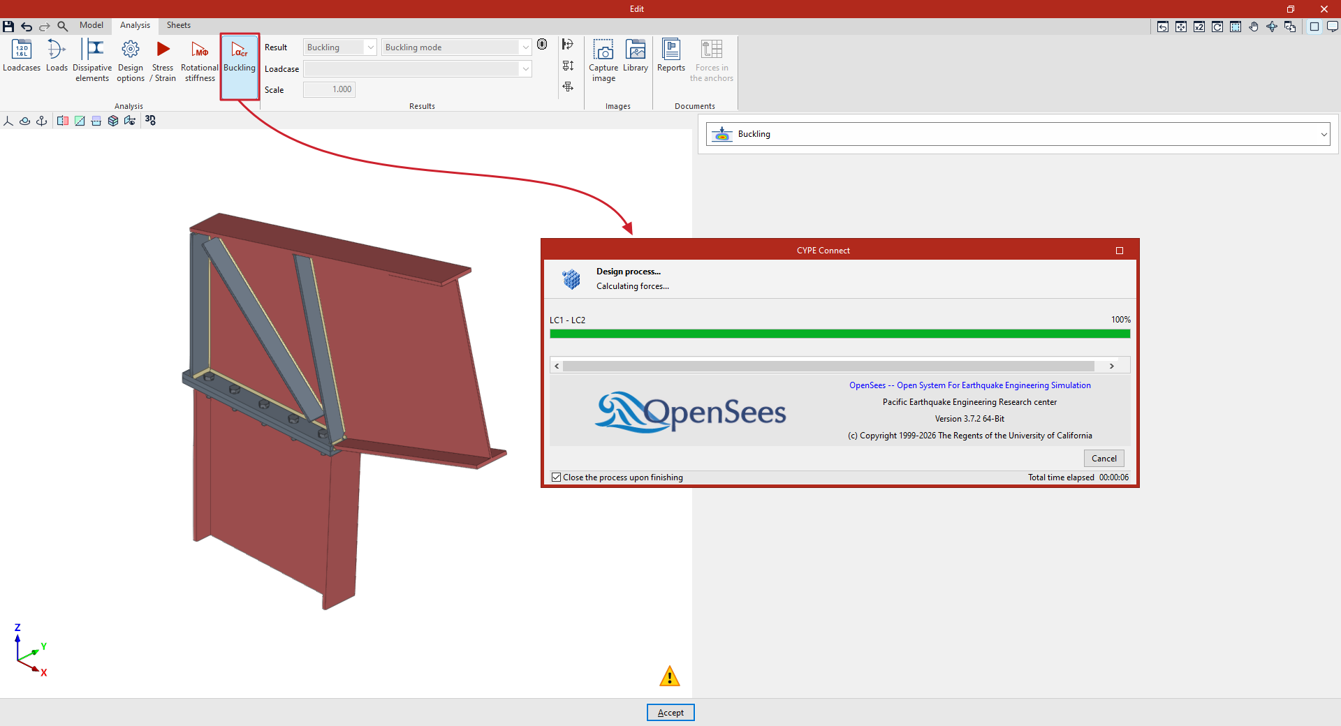
The following option in the top toolbar of the "Analysis" tab, within the connection editor, allows you to carry out the buckling analysis on each connection:

First, configure the "Loadcases" and the "Loads" acting on each section using the options in the top toolbar. These may have been generated automatically using the "Generate from BIM model" option.
Furthermore, under "Design options", you can adjust two parameters relating to buckling analysis:
- First, select the "Number of buckling modes" you want to analyse.
- Secondly, the buckling analysis can be carried out using the same loads as the "Stress/Strain" analysis or using a different set of loads. This can be controlled by ticking or unticking the "Perform the instability analysis with the same loads as the Stress/Strain analysis" option.
Buckling
The "Buckling" option allows you to perform a buckling analysis or local stability analysis of the connection components. The local buckling of a connection component occurs due to compressive stresses and depends, to a large extent, on the stiffness of the component and the distribution of the applied loads. The buckling analysis helps to identify unstable configurations in a connection design under the action of a specific loadcase.
There are several ways to evaluate the buckling phenomenon using finite elements. The method implemented in the connection analysis is linear buckling analysis, which allows the critical load factors for the different local buckling modes of the connection to be obtained for a given loadcase.
Once completed, you can view the results provided by the program to continue your work, such as the critical load factors for each buckling mode and its corresponding deformation. The smaller the first critical load factor, the closer the connection is to an unstable configuration.
Viewing buckling analysis results in the connection editor
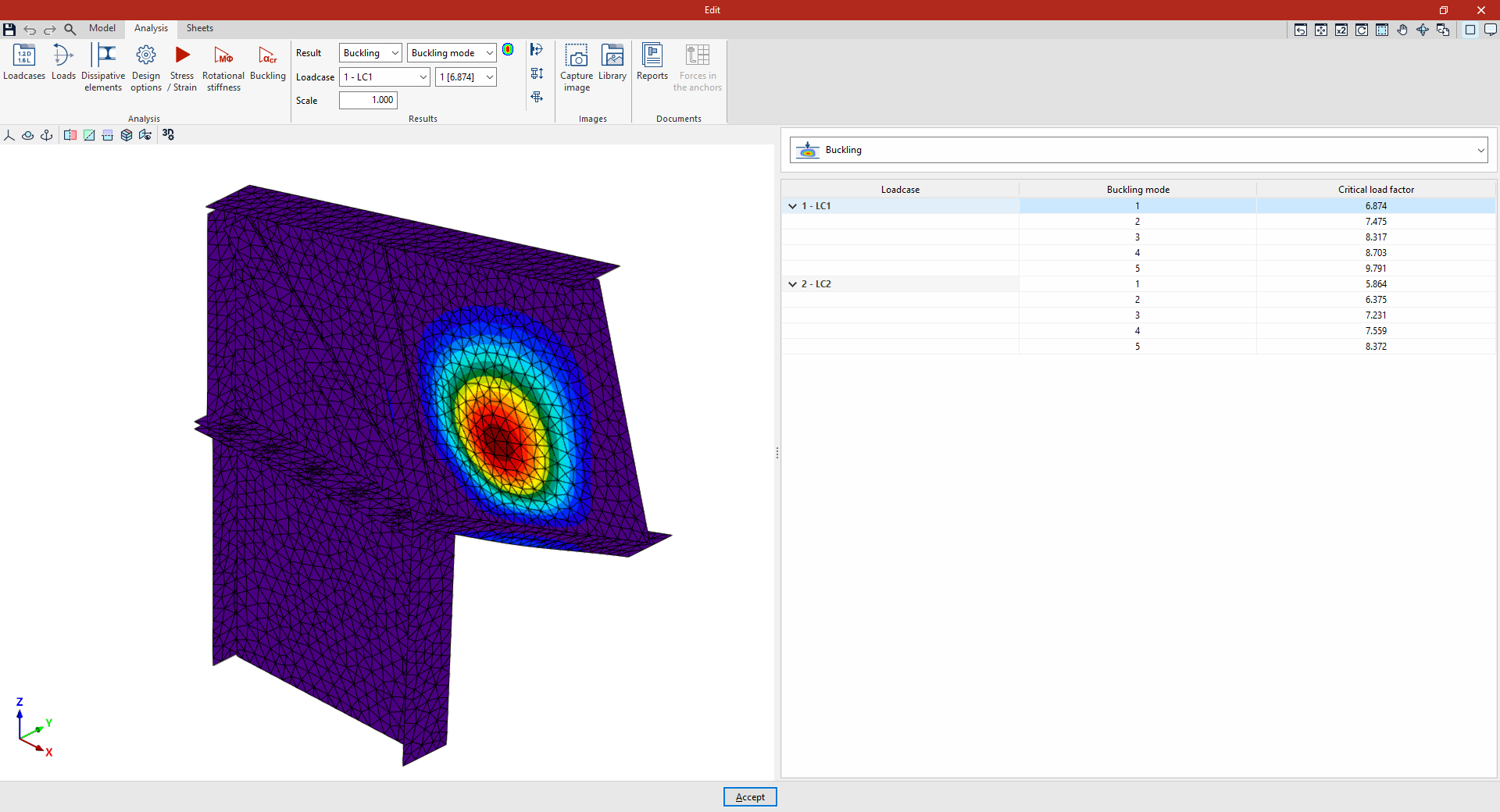
You can view the results after carrying out the buckling analysis of a connection in the program by using the options in the "Results" group on the top toolbar of the "Analysis" tab within the connection editor.

From the "Result" drop-down menu, select "Buckling" and then, from the drop-down menus below, select the "Loadcase" and "Buckling mode" you wish to view.
You can also change the model’s display "Scale" by entering the value in the relevant field.
Deformation
The viewport on the left displays the deformation and contour plots for the selected loadcase and buckling mode, using a colour code, as well as the discretisation of the connection elements.
Critical load factors
In the right-hand panel, selecting "Buckling" from the drop-down menu displays a table showing the "Buckling mode(s)" for each "Loadcase" and their corresponding "Critical load factors".
Clicking on each mode in the table will display the corresponding deformation in the viewer.
Display options
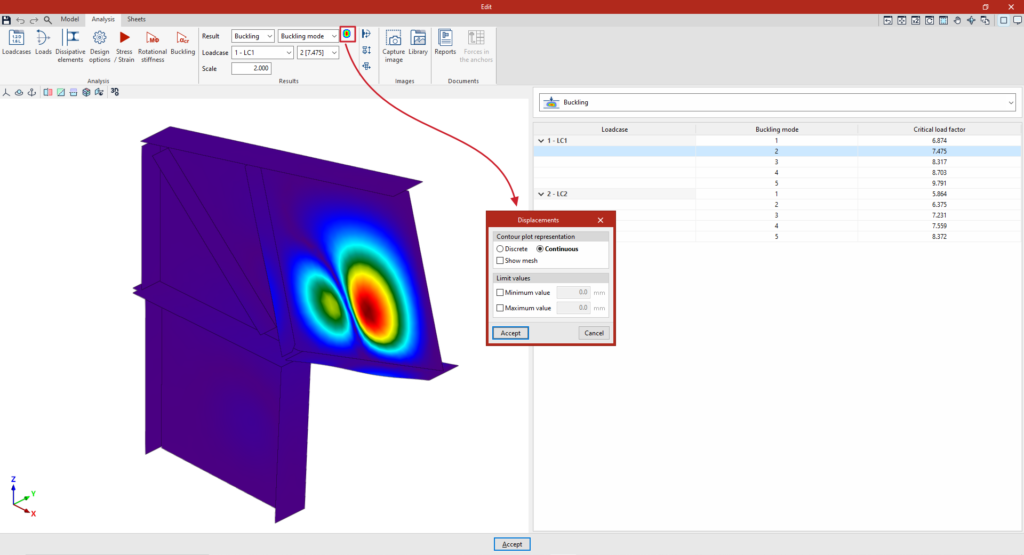
To the right of the "Result" drop-down menu, you can configure the "Display options" to adjust the result views by contour plots:
- The "Contour plot representation" can be "Discrete", if you want the program to use a finite colour scale, or "Continuous" if you want it to use a gradient.
- The "Show discretisation" option is also included, which allows you to show or hide the finite element mesh by toggling it on or off.
- In addition, "Limit values" can be specified for the display of results by adjusting both the "Minimum value" and the "Maximum value" of the scale.
Reports
In the connection report, under the "Buckling" section, there is a table showing the number of buckling modes calculated for each loadcase, as well as the critical load factors associated with each of them.
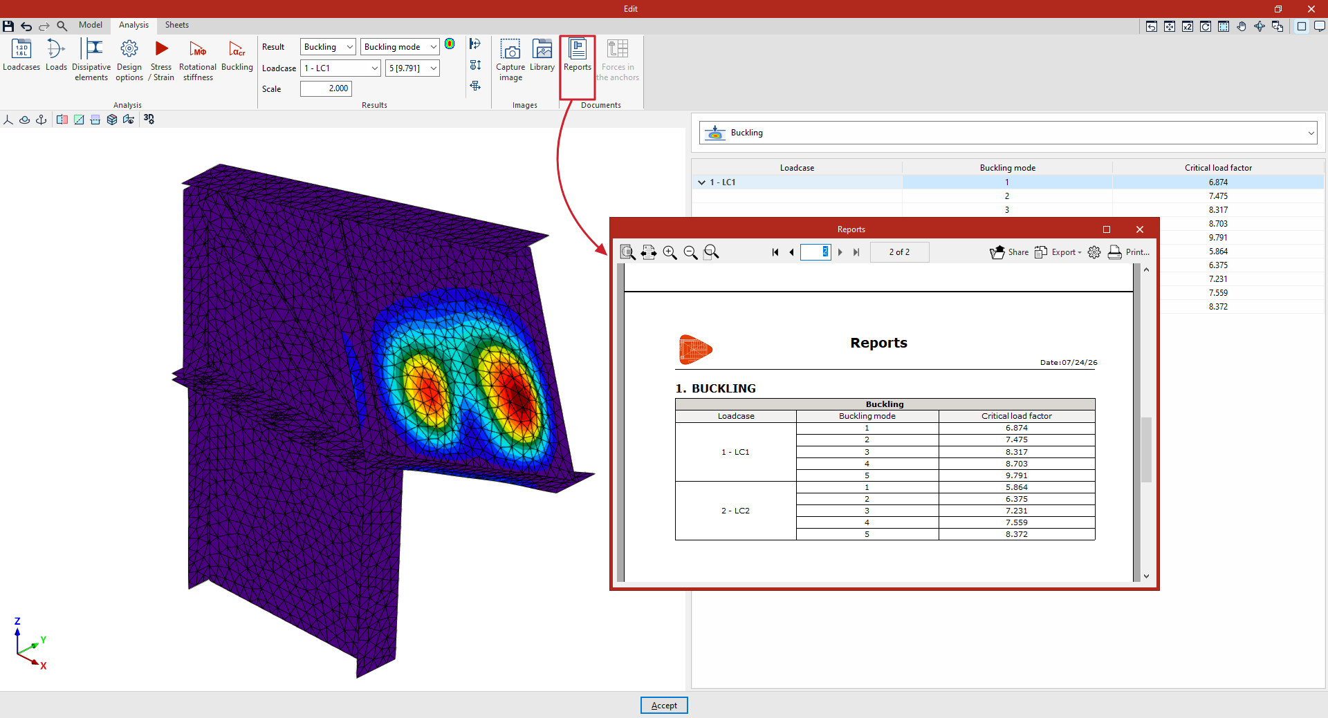
Table of contents
Complete your tour of CYPE Connect by exploring the other sections available:
