Update history​

Open BIM Layout

Clear cache

The "Clear cache" button has been added to the CYPE applications included in the Open BIM workflow in the "Configuration" dialogue box that opens with the following sequence of commands: Select any of the options in the "BIMserver.center" tool group > "Configuration" option in the dialogue box that appears. When clicking on "Clear cache", the following options are displayed:

  • Projects
    Deletes projects, contributions and documents downloaded from the platform that are in the "File directory stored in local cache".

  • Sessions
    Deletes the data of any active sessions. This action will require applications to be re-authorised to access BIMserver.center.

  • Log files
    Deletes transaction logging from applications with BIMserver.center.

Long access paths

In previous versions, file paths used by applications were limited to a maximum length of 256 characters. This restriction is not specific to CYPE tools but is set by default in the Windows file system. As of version 2024.b, CYPE applications can bypass the restriction and allow the use of an extended path length for a maximum total path length of 10,000 characters. This eliminates the problems caused by the default limit and allows users to work with long access paths.

This improvement is particularly useful when working on projects with a complex directory structure or with long file names. By allowing longer paths, CYPE applications offer greater flexibility in file organisation.

Applications available in Japanese

As of version 2024.a, the following applications are also available in Japanese:

  • CYPE Architecture
  • IFC Uploader
  • Open BIM Analytical Model
  • Open BIM Layout
  • Open BIM Model Checker
  • Open BIM Site
  • Plugin Open BIM - Revit

Applications available in Russian

As of version 2024.a, the following applications are also available in Russian:

  • CYPE 3D
  • CYPE Architecture
  • CYPE Connect
  • CYPECAD
  • IFC Uploader
  • Open BIM Layout
  • Open BIM Model Checker
  • Open BIM Site
  • Plugin Open BIM - Revit
  • StruBIM Steel

New method for connecting applications to the BIMserver.center platform

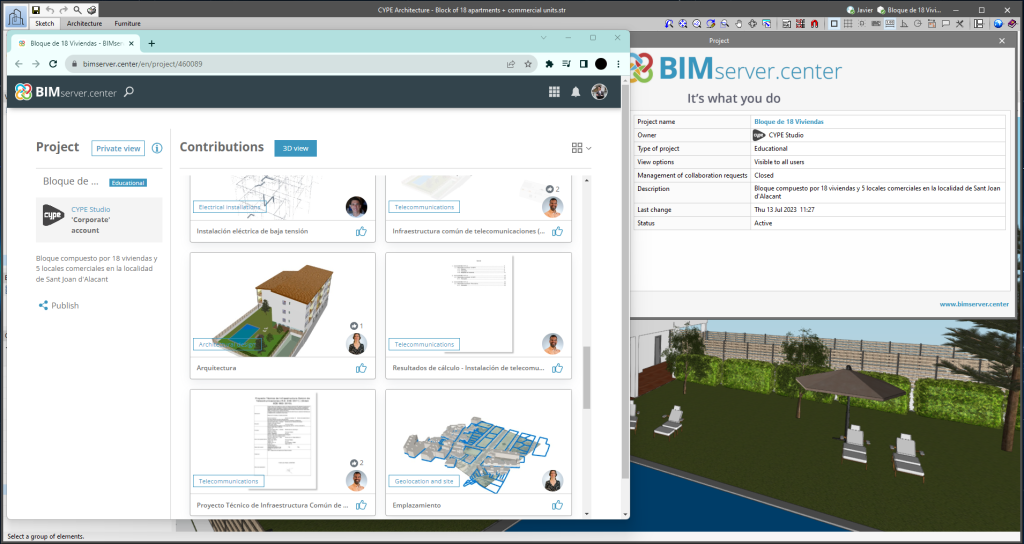
The mode of communication between Open BIM applications and the BIMserver.center collaborative work platform has changed. In previous versions, the applications used the "BIMserver.center Sync" tool to upload and download the files of the contributions associated with the project from the platform. This tool was downloaded from the BIMserver.center platform or installed together with the installation of the platform applications if users so desired.

From version 2024.a onwards, applications are now able to work directly with BIMserver.center without an intermediary. That is, without the need for the "BIMserver.center Sync" tool.

This modification will improve the performance and efficiency of Open BIM applications significantly. By removing this dependency, the applications have more autonomy and the waiting times for communication between BIMserver.center Sync and the program have been considerably reduced. The process of downloading contributions has also been optimised, as users no longer need to obtain the entire content of a project from BIMserver.center in order to work, but only the contributions to be read.

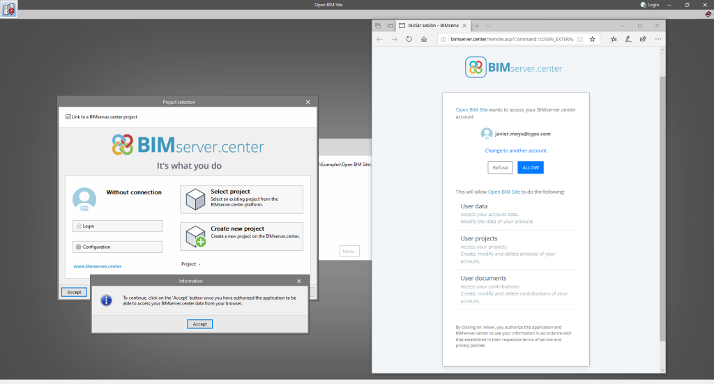
The way of authenticating a BIMserver.center user in the applications has also been modified. Now, this process is carried out within the BIMserver.center web platform. To do this, the application with which the user is working will run the user's default browser when the "Login" button is pressed. When the credentials are entered, or after opening the browser if the user is already connected to the platform, an authorisation page will be displayed. This page details the resources the application is requesting access to and two buttons for granting or denying this access.

The authorisation must be carried out for each application. Once access has been granted, it is saved for the next time the program is run and there is no need to perform this process again for that application.

As well as performance improvements, changes have been made to the user interface of the Open BIM applications regarding the connection to BIMserver.center.

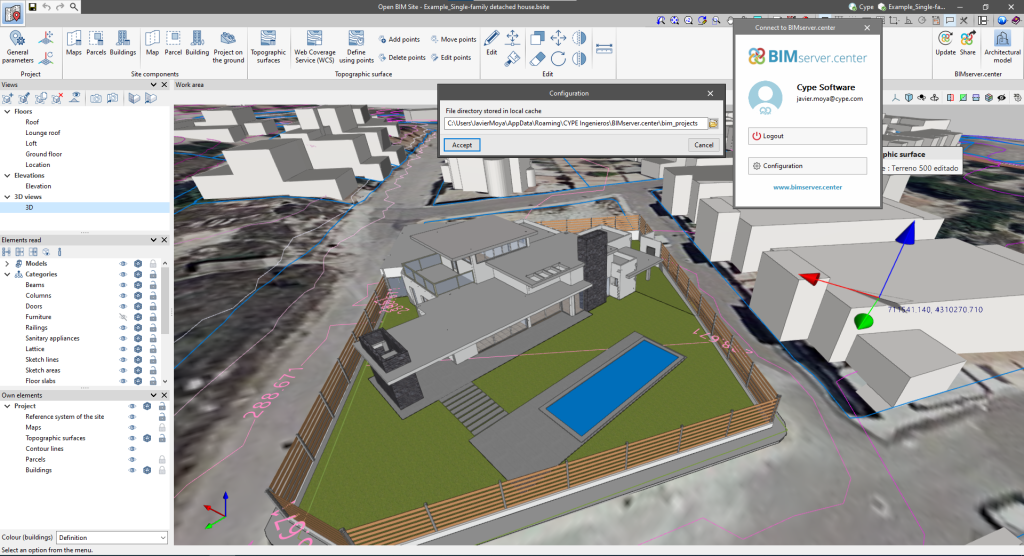
  • The "Connect to BIMserver.center" window now includes a "Configuration" button. Clicking it launches a menu from which you can edit the "File directory stored in local cache". This is the path where the files that make up the contributions will be downloaded when working with them from the applications. In previous versions, this location could be selected from the BIMserver.center Sync tool.
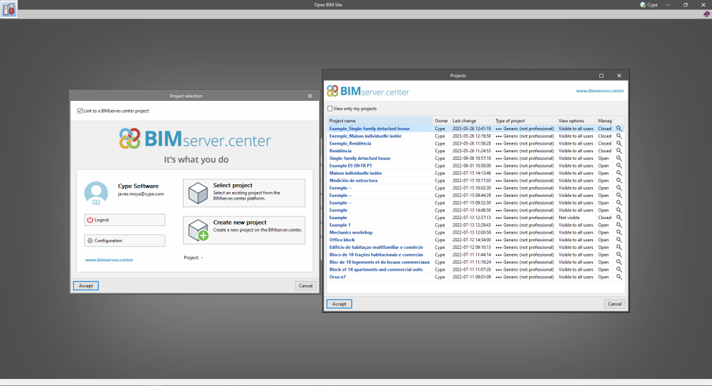
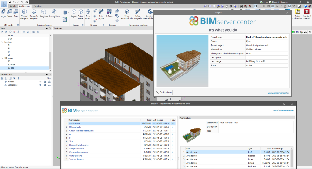
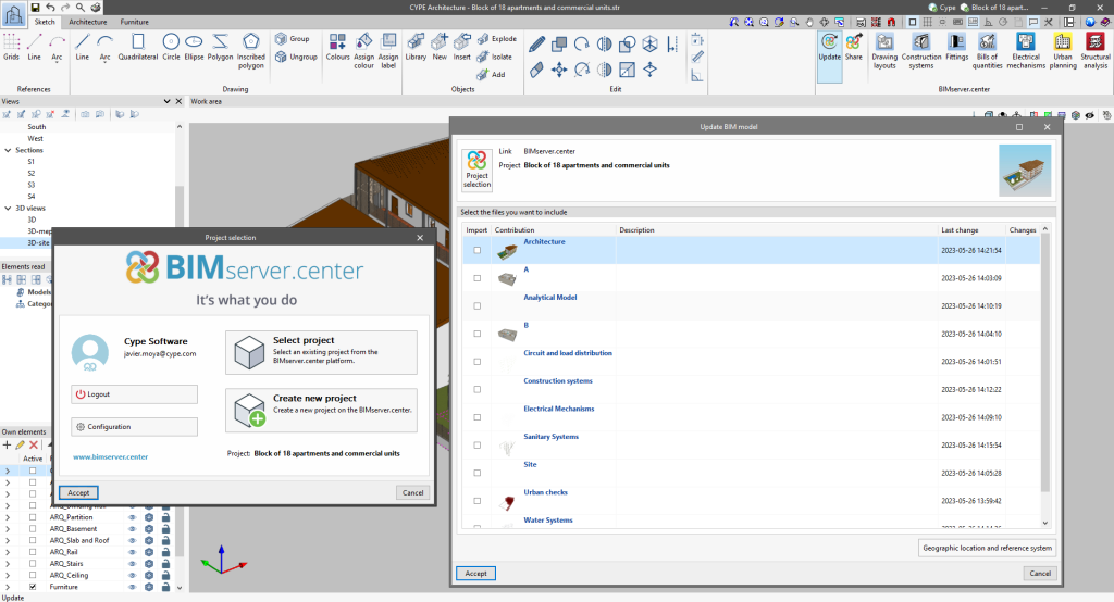
  • The appearance of the "Project selection" window has been modified.
  • In the "Select project" list, the "View only my projects" option has been added to show only the projects where the connected BIMserver.center user is the owner. Icons have also been included for the "Type of project" column in order to make it easier to identify them. The detailed data of a project now shows the image of each contribution, the description and the tags.
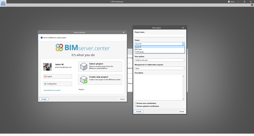
  • The "Review new contributions" and "Review updated contributions" options have been added to the "Create new project" window.
  • The list for selecting contributions ("Import BIM models") now includes the images of the contributions and the tags. The name of the contribution will be displayed in blue to indicate that the owner is the logged-in user.
  • When sharing a contribution or selecting contributions during the process of linking to a BIMserver.center project, a progress window will appear during the upload or download process.

To work in BIMserver.center with versions of Open BIM applications prior to 2024.a, users must continue to use the BIMserver.center Sync tool. This is still available for download from the platform and was included in the installation packages of the CYPE Open BIM applications prior to 2024.a.

New option: "Represent lines with print thickness"

Within the "View on screen" options, the "Represent lines with print thickness" option has been implemented, which allows users to view vector scenes in two ways, with or without the print thickness.

Dockable windows

As of version 2023.e, some CYPE applications have a new dockable window system that replaces the main screen user interface. As a result, users can now customise the workspace to suit their needs.

The list of applications that have this dockable window system appears at the end of this new feature. In future versions, the number of applications with this window system will be increased.

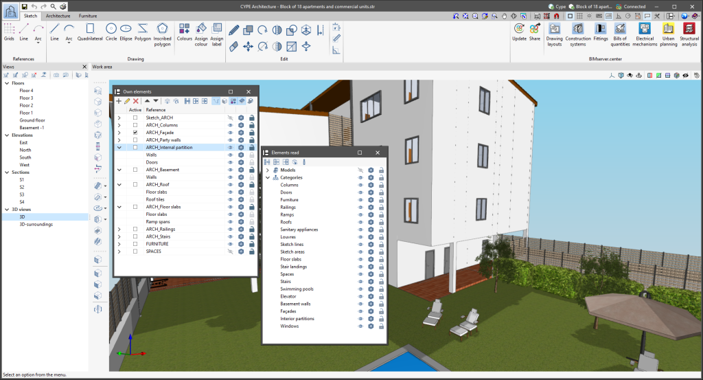
Dockable windows can be moved and resized. They can be either floating windows, pinned to a location within the application's main dialogue box, dragged outside of it, or even moved to another monitor.

  • Move windows
    A docked window can be moved by clicking on the title bar at the top of the window and dragging it.

    When dragging a dockable window, several visual aids are displayed to make its relocation easier. Next to the cursor, a text box appears containing the title of the dockable window being moved. Whenever the cursor approaches the edge of another window, a box appears showing a preview of the space it would occupy.

    It is possible to leave a window as a floating window without docking it to another window, and it is also possible to dock windows within a floating window. Holding down the CTRL key can prevent a floating window from being docked while it is being moved.

  • Group windows
    It is possible to group several windows in the same space by dragging one window to the top left-hand corner or to the bottom left-hand corner of another window. When this is carried out, tabs will appear at the bottom or top of the group, allowing users to alternate between the grouped windows. If the tabs are at the bottom, the title of the group of windows corresponds to the active window. On the other hand, if the tabs are at the top, they will be used as the title.

  • Show/Hide windows
    The icon to close the window can be found in the top right-hand corner of each dockable window.

    To manage the display of the dockable windows in the user interface, a "Window" button () has been added to the application environment, next to the "General Settings" button (icons on the top right-hand side of the program). By clicking on it, a drop-down menu appears with the available dockable windows and users are able to change their status. In addition, there is the "Reset Window Layout" option which allows users to restore the default workspace.

    In some cases, such as the "Work area" of applications with a 3D environment, the window cannot be hidden. In these cases, the icon for closing the window is not displayed and, in the "Window" menu (), the "Work area" will be locked.

  • Collapse windows
    When several dockable windows are arranged vertically, an icon is displayed, next to the close icon, which allows each window to be expanded or collapsed. When the window is collapsed, it will return to its previous size.

The window layout and display settings are saved when closing the application.

It is important to note that not all floating windows in an application are dockable windows. In order to tell them apart, the icon has been added to the title bar of windows that are dockable.

The following applications now include the new floating window environment in version 2023.e:

  • AcouBAT by CYPE
  • CYPE Architecture
  • CYPE Connect
  • CYPEFIRE
  • CYPEHVAC 3D
  • CYPEPLUMBING Water Systems
  • CYPESOUND
  • CYPETHERM LOADS
  • Open BIM Analytical Model
  • CYPE Construction Systems
  • Open BIM COVID-19
  • Open BIM Layout
  • CYPE Lightning
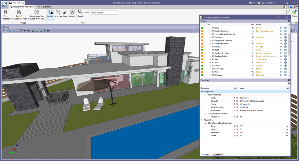
  • Open BIM Quantities
  • Open BIM Site
  • StruBIM Steel
  • The floating window environment also includes the "Bill of Quantities" tab in all applications that have this tab.

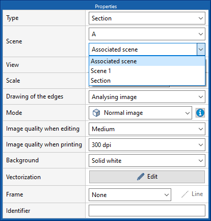
Use the section defined in one scene to create a section in another scene

The program allows users to draw a section based on a particular scene, and then associate the same section plane to a different scene.

Scale factor for user symbols

User symbols can be entered on a different scale than the one on which they were created. The scale can be defined on the "X" and "Y" axes of the symbol.

Copy the contents of a tag

This new tool allows content to be copied between the same type of tags. The content includes the variables of the tag.

Create tag based on an existing tag

This new tool allows users to create the same type of tag with the same content as the tag selected on the sheet. To do this, once the tool has been selected, users must select the tag they wish to copy and then the element to which they wish to assign the tag.

Graphical editing of the reference system of the model

Since version 2022.a, the applications integrated within the Open BIM workflow via the BIMserver.center platform include a tool for managing project reference systems. This option is available from the configuration window that appears when linking or updating a BIMserver.center project via the "Geographic location and reference system" option. As of version 2023.d, the applications now allow users to run a graphical environment where they can visually define a reference system for their model. To do this, the "Geographic location and reference system" window now contains the "Visual editing of the local reference system of the model" option.

From the "Visual editing of the local reference system of the model" window, the origin and orientation of the reference system of the model can be indicated in the workspace with the "Define the reference system of the partial model" tool. Both the axes of the reference system of the model, which we have just entered and the axes of the reference system of the site can be viewed in the workspace. The latter appears with a "Site" tag.

To make it easier to define the reference system, the 3D models corresponding to the BIMserver.center project contributions selected during the linking process are displayed. The management of the visibility and object snaps of these models is carried out from the "Elements read" menu in the left sidebar of the window. The "Views" menu can also be found in the same options bar, from which different types of 2D and 3D views of the model can be generated. These tools can already be found in several CYPE applications. For more information on how they work, please refer to the User’s Manual for the 3D work environment tools available in CYPE applications.

Apart from 3D models, 2D drawings or plans can also be imported from CAD files (".dxf", ".dwg", ".dwf") or images (".jpeg", ".jpg", ".bmp", ".png", ".wmf", ".emf", ".pcx"). These files and object snaps are managed through the "DXF-DWG Template" and "Template object snaps" options accordingly.

Once the editing is complete, the coordinates and orientation of the reference system of the model with respect to the reference system of the site are moved to the corresponding fields in the "Geographic location and reference system" window.