Share

General configuration options

The general configuration options are accessible via the "Configuration" button in the top right-hand corner of the interface of some CYPE programs.

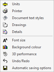
Clicking on this button displays a menu with different general configuration tools. The options displayed depend on the program being used.

The following options are available:

Automatic updates*

*Only in versions 2025.a and earlier. As of version 2025.b, the update notification is available in the program start window.

This activates the automatic update system for the programs:

  • Download program updates automatically (optional)
Note:
More information on the program's automatic update process can be found at this link.

Units

This is used to configure the project's system of units. The quantities available in the table depend on the program being used.

  • "Units" column
    Selects the unit of measurement for each of the magnitudes.
  • "Label" column
    Displays the label identifying the selected unit.
  • "Decimal digits" column
    Modifies the number of decimal places used to measure each magnitude in the selected unit.
  • Import one of the predefined systems of units
    Using this option available on the right-hand side, the units from one of the following predefined systems can be imported automatically:
    • International System of Units
      Imports the units from the International System of units.
    • I-P System
      Imports the units from the I-P (Inch-Pound) or imperial system.
  • Import/Export
    Using these options, the defined system of units can be imported and exported to files on disk.

Printer

Opens the "Page setup" window with the following options:

  • Printer selection and configuration
    Selects and configures the printer used for printing documents.
  • Scale
    Adjusts the scale when printing documents:
    • Do not scale
    • Apply only to the text
      • Scale (%)
    • Apply scale
      • Scale (%)
  • Divide page (optional)
    Prints the page divided into rows and columns:
    • Number of rows and separation between rows
    • Number of columns and separation between columns
  • Margins
    Modifies the margins on the printed page:
    • Top
    • Bottom
    • Left
    • Right
    • Binding
    • Symmetrical margins (optional)

Document text styles

Configures the styles of the documents. The characteristics of each style can be linked to those of the default font style, indicating whether it has the same or different font "Size", or unlinked, to define them independently.

  • Type of selected letter
    Sets the default font:
    • Font style
    • Font size
    • Colour
    • Line spacing  (0.7 lines / Single / 1.5 lines / Double)
  • Page header
    Sets the style used in the documents' page header. The format can be set to bold, italic or underlined and the alignment can be changed. The following editing panel can also be accessed:
    • Header configuration
      Sets the image and the data to be printed in the page header:
      • Header image
        • None / Predefined / User defined
        • Image on the left / Image on the righta
      • Print
        • Project (optional)
        • Location (optional)
        • Developer (optional)
        • Author (optional)
        • Date (optional)
  • Text body
    Configures the style used in the text body of documents. The alignment can be changed.
  • Page footer
    Sets the style used in the footer of documents. The formatting can be set to bold, italic or underlined and the alignment can be changed.
  • Style of the different chapter levels
    Configures the style used in the different levels of chapters, both in their "Table of contents" and in their "Contents". Using the "Copy from" option, the style defined in each level is copied to any other level. The style of one level can also be linked to the style defined in another level. Also, using the "Numbering" option, users can select the heading numbering system. The available levels are as follows:
    • Front cover
    • Level 1
    • Level 2
    • Level 3
    • Level 4
    • Level 5

Drawings

Configures the formats and peripherals for printing drawings.

  • Definition of page formats
    Configures the page formats and sizes available when printing drawings. Users can edit, add, copy or delete entries in two tables:
    • Format table
      The first table defines the series of available formats.
      • Format
    • Table of page sizes
      When selecting a format in the first table, the second table defines the page sizes available in the format and their dimensions:
      • Sizes, Dimension X, Dimension Y
  • Page margins
    Configures the print margins of drawings (top, bottom, left and right) around the "Print area".
  • Format viewer
    In this display area, the selected format series and the selected page size are shown schematically.
  • Configuration of peripherals
    Accesses to the printing peripherals configuration table. By default, the program includes the "DWG" and "DXF" peripherals, which allow printing on these files, together with the graphic devices registered in the operating system control panel. The configuration options available when editing each peripheral vary according to its type:
    • Configure drawing program
      This panel appears when editing the "DXF" and "DWG" peripherals and allows users to configure the printing on these files:
      • Font style
      • Format Data
        • Draw the inside margin for the format (optional)
        • Draw the outside limit for the format (optional)
      • Format
      • Compatibility
        • Symbol Ø
        • ASCII
      • Unit display (Metres / Centimetres / Millimetres / Inch)
      • Text alignment (Not justified / Justified)
      • Character map (MS-DOS / Windows / Without accents)
      • 'AutoCAD' version (AutoCAD 2004 / AutoCAD 2000 / AutoCAD R14 / AutoCAD R13 / AutoCAD R11)
    • Configure printer
      This panel appears when configuring a printer type peripheral:
      • Printer configuration
      • Orientation (Vertical / Horizontal)
      • Format Data
        • Draw the inside margin for the format (optional)
        • Draw the outside limit for the format (optional)
      • Format
      • Accepts Colour
        • In Colour (optional)
      • Page margins

Details

This tool is used to store user detail libraries to be included in the drawings later on.

Creating libraries

First, new libraries are created to hold the new details. These libraries can be organised in directories and subdirectories. When creating a new detail library, the program requires the following data:

  • "Create Library" window
    • Name of the library
    • Library description

Creating details

Details are created by importing DXF, DWG or image files. After selecting the library where the detail is to be imported, the program will allow users to import a file with the detail.

When importing a DXF or DWG, a dialogue box opens in which users must indicate the name to be assigned to the detail, a description, the drawing units with which the file is being created and the scale it is to be transferred to:

  • "New Detail" window (DXF and DWG files)
    • Detail name
    • Detail description
    • Units of import file (Metres / Centimetres / Millimetres / Inches)
    • Scale (1/n)

With this data, the program calculates the final dimensions that the detail will have in the plan. Thus, the "Size of import file" and the "Size in plan" are displayed.

In the next window of the import process, users can choose which layers should be visible, whether texts should be activated, the pen thickness and the layer name:

  • "Layer management" window
    • Visible, Layer name, Colour, Pen thickness, Thickness (mm), Visible text

When importing an image file, a dialogue box opens where the name to be assigned to the detail, a description and the data required to define its size in plan must be indicated:

  • "New detail" (image files) window
    • Detail name
    • Detail description
    • Size in plan
      • Width (mm)
      • Height (mm)
    • Keep aspect ratio (optional)
Note:
To add user details to the drawings, use the "Details"option available in the drawing printing process of each program, go to "File", then to "Job drawings" and finally to "New". Then select the "Add user detail" option.

Also, default details from the CYPE library can be included if they are available in the program by selecting the "Add" option. This is the case of the CYPECAD construction details library.

Sending jobs

Allows users to configure the data related to sending jobs.

  • Recipient
    Selects the recipient of the jobs sent by clicking on "File" and then on "Send".
  • Recipients and addresses
    Consults and edits the name and address of the recipients of the jobs to be sent.
Note:
In the event of any query or problem with the program, the communication channels available at the following link can be used to contact CYPE Technical Support.

Font size

Used to set the font size on the screen to adjust its readability. The program must be restarted for the changes to take effect.

  • Set custom font size (optional)
    • Basic size

Background colour

Sets the background colour of the work area.

3D performance

Sets the parameters related to 3D performance.

  • Antialiasing
    Antialiasing, also known as edge smoothing, is a process that improves the appearance of an image by reducing the level of pixelation at the edges of geometric primitives. Depending on the technique used, the hardware available on the PC and the configuration of the video card driver, the graphics performance may be affected. The available configuration options are:
    • No
      No edge smoothing technique is applied. The graphics speed is as fast as possible. The edges of the geometric primitives in the image are clearly pixelated when they are not aligned with the horizontal and vertical directions of the screen.
    • FXAA
      This is a software technique that can be applied with any video card. The image quality is good and the impact on graphics speed is minimal. This is the recommended setting for work areas.
    • MSAA
      This technique can only be applied with video cards that support it. The image quality is good, and the edge definition of geometric primitives is excellent at 4 samples and above. However, depending on the PC hardware, the graphics speed may be affected. This is the recommended value for display areas.
    • FX+MSAA
      Combines the two previous techniques and produces an image of excellent quality.
  • Improved environment lighting quality level (SSAO)
    • Low / Medium / High / Maximum
  • Drawing quality level of transparent objects
    • Low / High
  • Drawing quality level of the transparent objects when moving or rotating
    • Low / High
  • Enable hardware occlusion queries
    • Yes / No

Undo/Redo

This activates and configures the actions related to the "Undo" and "Redo" options, available at the top left of the program's interface.

  • Activate Undo/Redo (optional)
    • Maximum number of actions

Auto-save options

Configures the automatic saving carried out by the program.

  • Automatically save every n minutes (optional)
  • Save after analysing or designing (optional)