
Start screen
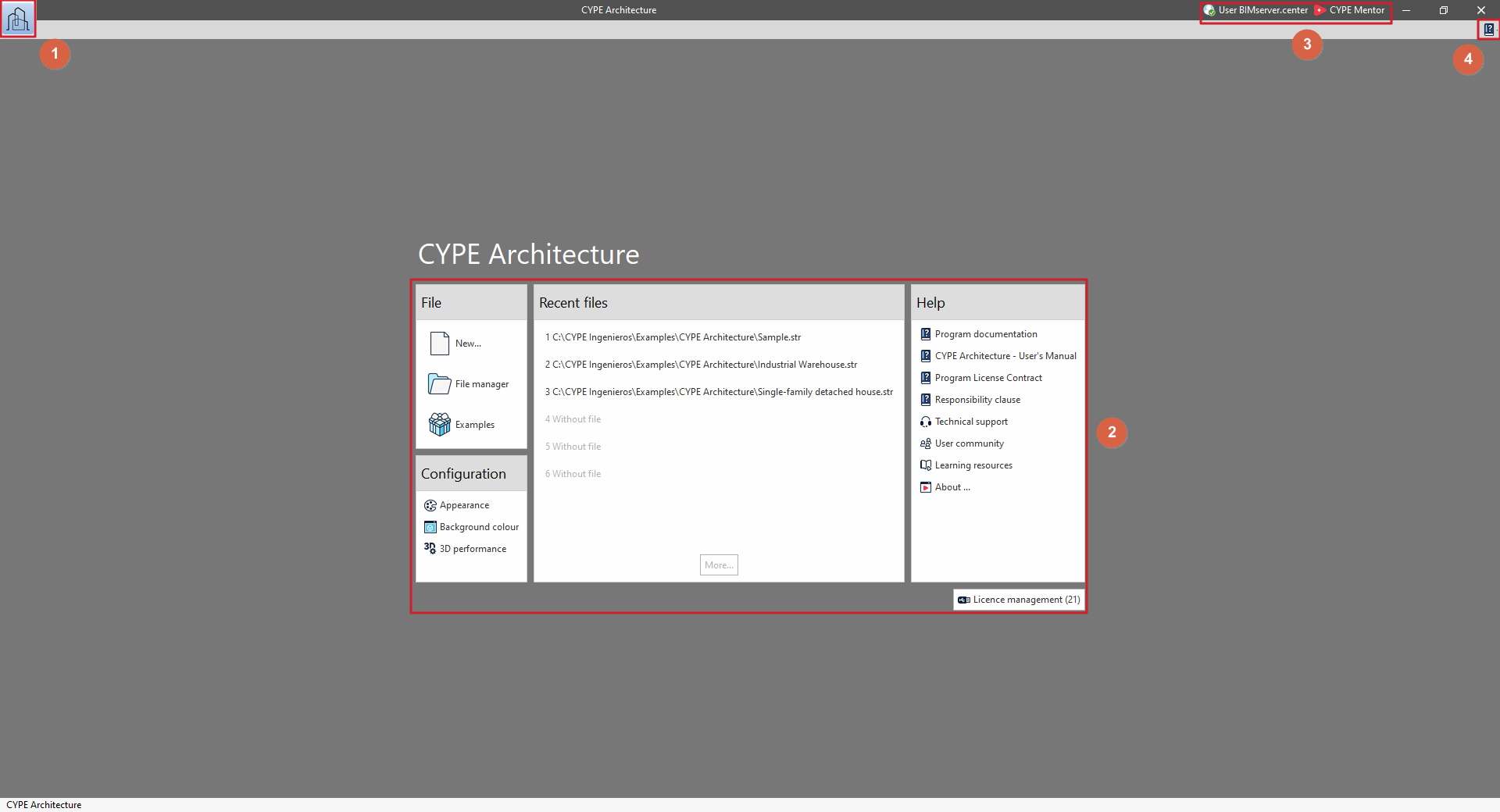
The default interface or start screen of CYPE programs appears when the app is opened and features the following options and menus:
- "File" menu (1)
Create, open or save projects and access the file manager. - Central area access points (2)
The panels in the central area allow you to do the following:- In the "File" section on the left, you can create and open a "New" file, open "File manager" to search for files, or load the "Examples".
- In the "Settings" section, you can change the "Appearance", "Background colour" or "3D performance".
- In the "Recent files" section, in the centre of the screen, the path to the most recently opened files is displayed; clicking on each one will open that file.
- The options in this menu are displayed in the "Help" section on the right.
- This section also displays a notification that a new version of the program is available, where applicable.
- Finally, the "Licence management" option allows you to open the relevant panel, where you can activate and view the permissions for the licence currently in use.
- Tools in the top-right-hand corner (3)
Check the connection to BIMserver.center and access CYPE Mentor. - "Help" menu (4)
Access the help menu options.
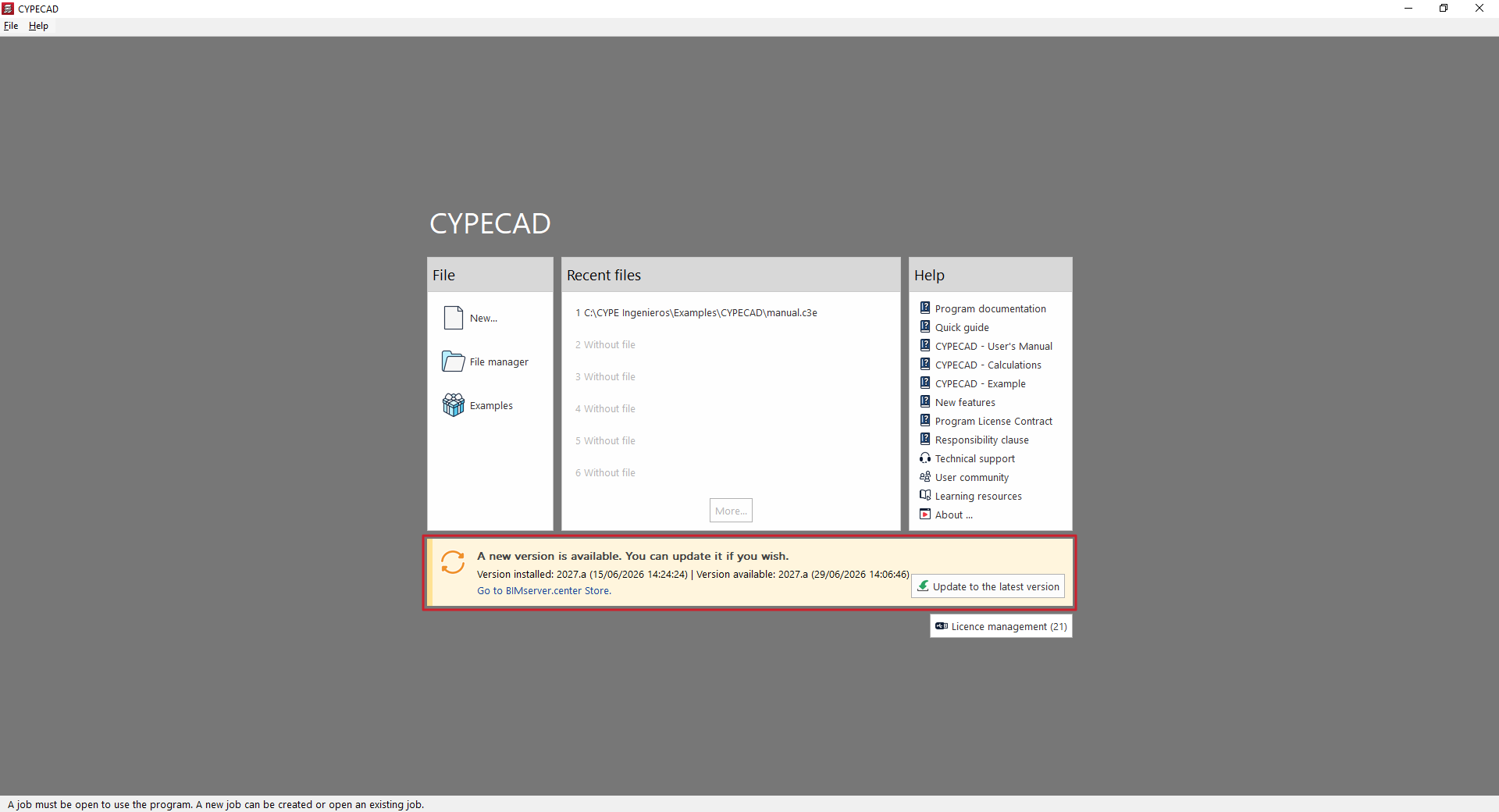
Notice: New version available
If a newer version of the program is available, a notification will appear in the central area of the start screen.
This message provides information on the "Installed version" and the "Available version”, along with a direct link to the Store page on the BIMserver.center web platform.
Clicking the "Update to the latest version" button automatically starts the process of downloading and installing the app. This feature ensures that you are always using the most up-to-date version of the software, allowing you to benefit from the latest enhancements.
In any case, the program can still be opened and used even if it is not updated to the latest version.
Main interface
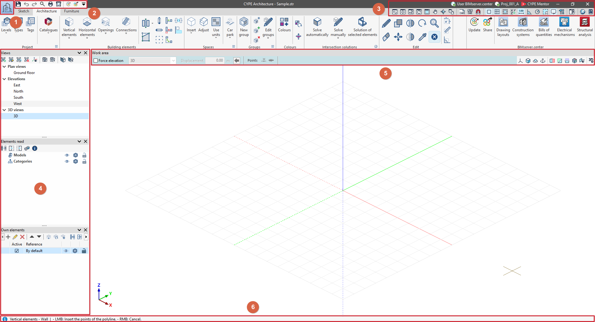
The main interface of CYPE programs is displayed when a project is opened and features various general tools organised into the following areas:
- "File" menu (1)
Create, open or save projects and access the file manager.
- Tools in the top-left corner (2)
Save the file, undo and redo changes, and generate reports and drawings. Also used to search for and quickly access other program features.
- Tools in the top right-hand corner (3)
Change the drawing views, manage templates and their snapshots, activate various tools for inserting elements, control the dockable windows system, access the general configuration options and open the "Help" menu. They also allow you to check the connection to BIMserver.center and access CYPE Mentor.
- Left-hand side panel (4)
By default, this area contains the panels for managing views, levels, read elements and own elements.
- Tools in the "Work area" (5)
The top of the "Work area" window contains options for adding elements to the workspace (on the left) and tools for controlling the visibility of the 3D model (on the right).
- Status bar (6)
This is located at the bottom of the main interface and displays contextual information about what is currently happening in the program.
"File" menu
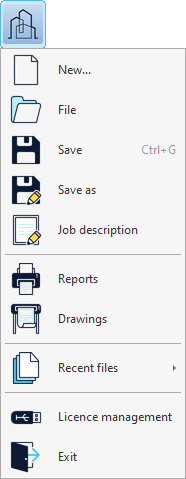
The "File" menu can be accessed by clicking the icon with the program logo in the top-left corner of the program's main interface.
The following options are available:
- New
Creates a new job, closing the job that is already open. The program will also ask if the data of the current job is to be saved.
- File
Opens the file manager, closing any project that is currently open. The program will ask if you want to save the data for the current project. It will then open the "File manager" window, where you can locate files that the program can read and perform operations such as opening, searching for, compressing and sharing existing projects, or loading the examples.
- Save (Ctrl + G)
Saves the current job.
- Save as
Saves the current job by specifying a different file name, save path, and description.
- Job description
Checks and modifies the current job’s description.
- Reports / Drawings
Provides the reports or drawings of the current job.
- Latest files
Checks and opens the latest files opened with the program.
- Licence management
Opens the "Licence management" panel.
- Exit
Exits the app and closes it. The program will ask if you want to save the data for the current project.
File management
The file manager is used to locate and manage files readable by the program, performing operations such as opening, searching, compressing and sharing previously created jobs, creating new jobs, copying them, deleting them or loading examples.
To access the file manager, open the "File" menu at the top left of the program interface and select the "File manager" option to open the window with the same name.
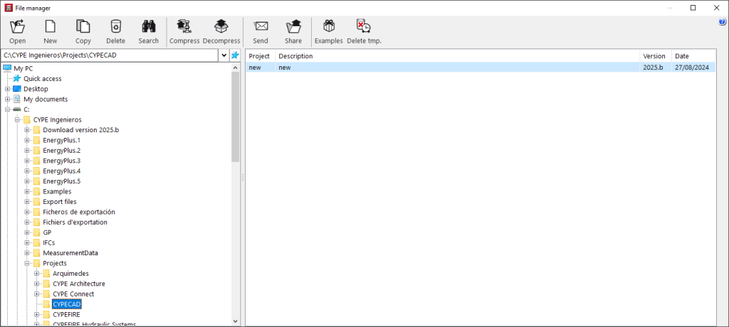
In this window, in the browser on the left-hand side, users can browse and select any folder on the local disk or in the network environment.
On the right, there is a table with the list of jobs in the selected folder that can be opened by the program being used, with the following information:
- Name of the job
- Description of the job
- Saving version
- Save date
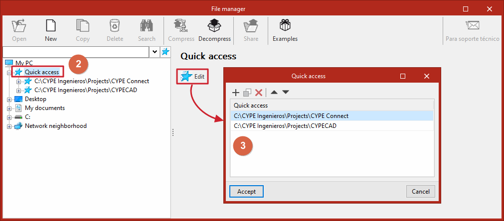
If you select a particular route and click on the button with the blue star symbol (1), that route is saved in the "Quick access" section of the browser. This makes it easy to find the route the next time you open the program by expanding the "Quick access" row (2). Furthermore, by clicking on the "Quick access" row, you can edit the list of quick access entries created using the corresponding button (3), create new entries or delete them.

The file manager has the following tools at the top:
- Open
Open the selected job. A job can also be opened by double-clicking on it.
- New
Create a new job. This tool is the same as the "New" option in the "File" menu.
- Copy
Copy the selected job after entering the copy name.
- Delete
Delete the selected job, sending it to the recycle bin.
- Search
Search for an existing file by entering its name.
- Compress
Generate compact files with a .cyp extension that can be useful to save backup copies or to exchange the model information with other users. Clicking the button on the right allows users to choose the path in which the compressed file is to be saved.
- Decompress
Decompress a file with a .cyp extension. To do this, a file compressed in .cyp must be searched for and selected through the operating system explorer. By clicking "Open" and accepting the following dialogue boxes, the program will dump the information contained in the file into the selected path. After it has been decompressed, double-click on the job in the list to open it.
- Send
Compress and send the selected job via an automatic connection to the e-mail program configured on the computer.
- Share
Generate a private link to download the file, which is hosted on its own server. Only people in possession of this link will have access to the job. This option can be useful for sharing the model information with other users of the program. The users who receive the link, after clicking on it, will download a file with a .cyp extension that can be "Unzipped" using the option mentioned above.
- Examples
Install and open any of the sample jobs that are built into the program by default, overwriting the existing ones.
- Delete temporary files
Delete the temporary files resulting from the analysis of the selected job. These files are essential for resizing the job, but not for obtaining the plans. This option appears only in some programs.
Save, undo and redo options. Search and quick access tools
The group containing the options for saving the file, undoing and redoing any modifications and the quick access toolbar can be found in the top left-hand corner of the interface.

The following options are available:
- Save (Ctrl + G)
Save the file.
- Undo (Ctrl + Z)
Undo the last modification.
- Redo (Ctrl + Y)
Redo the last modification.
| Note: |
|---|
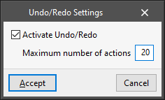
| The maximum number of "Undo/Redo" actions can be configured by going to "Settings" and then to "Undo/Redo" in the top right corner of the general interface. |
- Search and activation of commands and options (Ctrl + F)
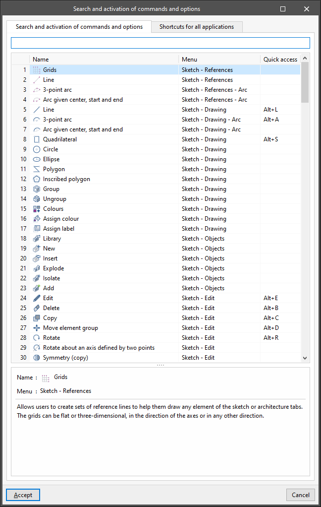
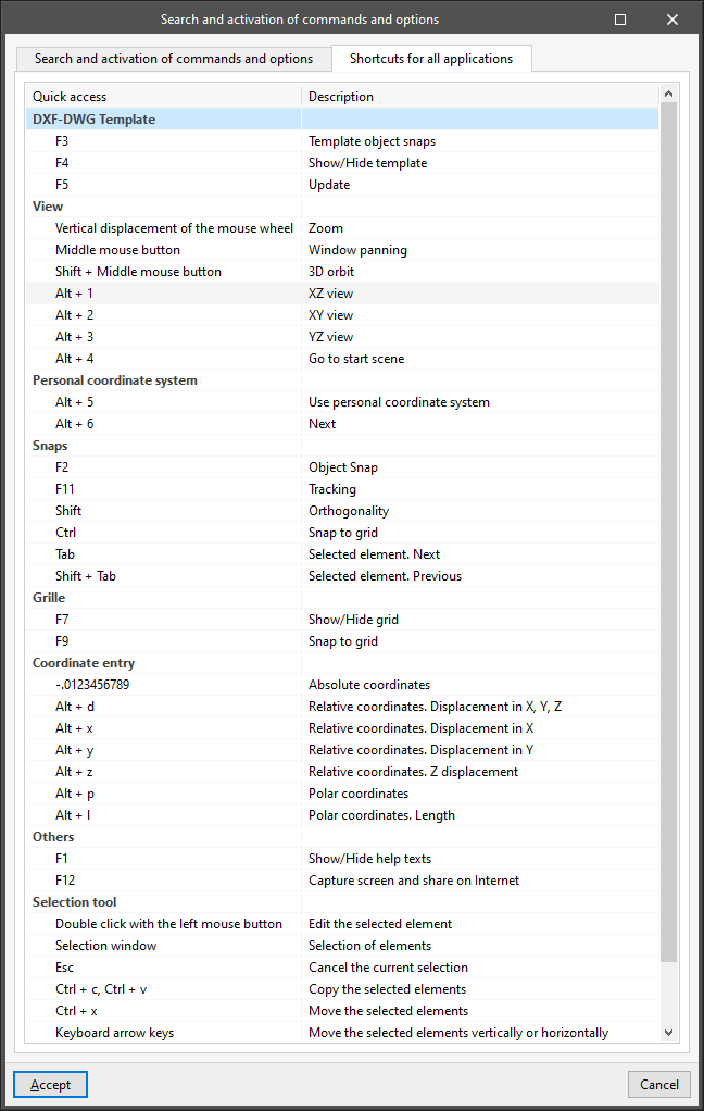
Clicking on this option opens a window with the following tabs:- Search and activate commands and options
Users can quickly access the program's options, indicating the “Name”, the “Menu” where they are located and the corresponding “Quick access” command. - Shortcuts for all apps
Check the “Quick access” options for all the apps as well as their “Description”.
- Search and activate commands and options
- Reports
Provides job reports.
- Drawings
Provides job drawings.
The next section of this group consists of a configurable toolbar for quick access:
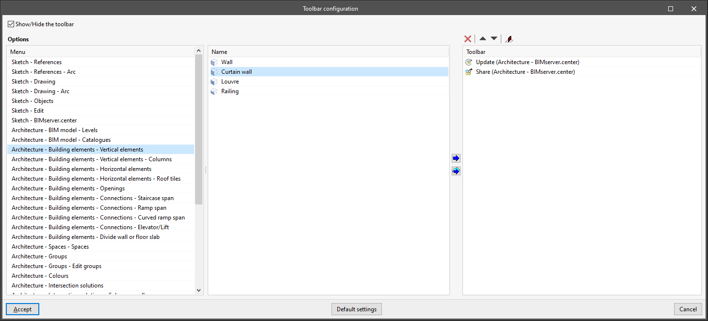
- Toolbar configuration
Configure the options visible in this section. Clicking on this option opens a window with the following options:- Show/Hide the toolbar
Show or hide the options in this section. - Options
On the left are two lists with the "Name" of all the options available in the program, sorted by the "Menu" in which they are located.
On the right is the list of options visible in the quick access "Toolbar". The tools at the top can be used to delete, reorder or place a separator between the options incorporated in the toolbar.
Using the buttons in the lists, users can incorporate the selected option or incorporate all the options from the selected menu into the toolbar. - Default settings
Loads the default configuration of this toolbar.
- Show/Hide the toolbar
Tools for drawing views
The group of tools for drawing views is located in the top right-hand corner of the interface and allows users to control the drawing views on the screen.

The following options are available:
- Previous window (Ctrl + P)
Restores the previous drawing view to the current view.
- Full window (Ctrl + W)
Displays the entire drawing. The same action can be performed by double-clicking on the middle mouse button.
- Zoom out 2X
Enlarges the view of the drawing to twice the size of the drawing compared to the "Full window" option.
- Redraw (Ctrl + R)
Redraws the current view of the drawing without changing its size.
- Highlight zoom (Ctrl + M)
Zooms in and out by clicking on the drawing. To do this, a window is drawn to adjust the view to the set size. The mouse wheel can also be used, where the zoom level can be increased or decreased to zoom in or out.
- Window panning (central mouse button)
Changes the position of the drawing. To do this, after activating the option, left-click on the screen and, holding down the button, move the cursor. The central mouse button can also be pressed and, while holding it down, it can be dragged. Once this is done, press this option again to deactivate it and continue with the previously used option.
- 3D orbit (Shift + central mouse button)
Rotates the scene around the rotation pivot. To do this, after activating the option, left-click on the screen and hold down the mouse button to move the cursor. Alternatively, the "Shift" key and the central mouse button can be pressed and, while holding them down, dragged. Once a rotation has been carried out, press this option again to deactivate it and continue with the previously used option.
The 3D orbit behaviour depends on the options marked in the top toolbar of the work area:- If the "Rotation about a point" option is activated, the point under the cursor will be used as the rotation pivot.
- If the "Rotation about the camera" option is activated, the scene rotates around the vertical axis of the camera.
- Otherwise, the pivot shall be analysed considering the visible elements in the scene.
- Print the current view
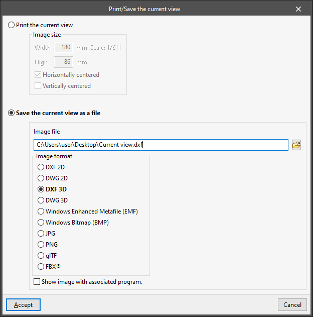
Prints the current view displayed in the work area or generate a file with the drawing in a graphical format. If the current view contains a template, this template will also be included in the drawing.
When using this tool, the "Print/Save current view" window opens with the following options:- Print the current view
Prints the current view displayed in the work area after configuring the following settings:- Image size
- Width
- High
- Horizontally centred (optional)
- Vertically centred (optional)
- Image size
- Save the current view as a file
Generates a file with the drawing in the selected graphic format.- Image file
Configures the path where the file will be saved. - Image format
Selects the file format.- DXF 2D
- DWG 2D
- DXF 3D
- DWG 3D
- Windows Enhanced Metafile (EMF)
- Windows Bitmap (BMP)
- JPG
- PNG
- glTF
- FBX©
- Show image with associated program (optional)
Opens the file generated with the program associated with the selected format.
- Image file
- Print the current view
Importing DXF, DWG, PDF and JPG files
CYPE programs feature the following set of tools at the top of the screen, which are used to import and view files in various formats (such as DXF, DWG, PDF and JPG) to use them as base templates for your drawings:

Import DXF and DWG files
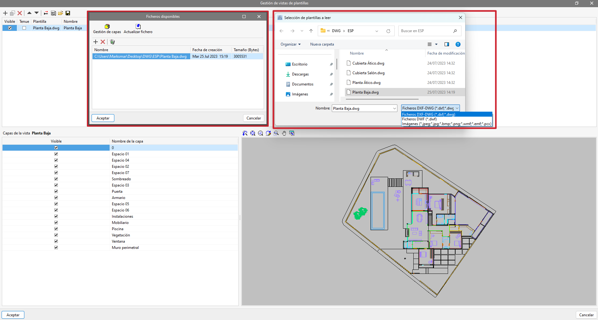
When you click on the first tool, "Import DXF-DWG templates", a pop-up window called "Template views manager" will open, where you can manage templates, transform them (where necessary) and import them into the project in DXF, DWG, PDF or JPG format, amongst others.
When clicking the "Add" option, the "Available files" window will appear. Here, you can add a new file with "Add" and change the file type to be displayed. The default format is "DXF-DWG files", but it is also possible to import "DWF files", "Images" (in .jpeg, .jpg, .bmp, .png, .wmf, .emf and .pcx formats) and "PDF files". After selecting the file from its path or location on the disk, click "Accept". If the document consists of several pages, the "Page number" to be imported must be specified.
This will add the file to the list in the "Available files" window. From here, you can carry out the "Layer management" on the template or "Update the file" if it changes. If you select a file from the list and confirm, it will be added to the list of template views in the "Template views manager" window.
Enable DXF-DWG templates (F4)
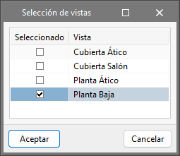
Once the templates have been imported into the project using the option above, select the tool on the right, "Activate DXF-DWG templates (F4)", to proceed to "Select views" of the templates you wish to display in the pop-up window.
Once you have selected the desired template view(s), click "Accept", and they will appear in the graphics window or workspace of the current view.
The F4 key can be pressed as a shortcut to toggle the display of all templates in the view.
Template object snaps (F3)
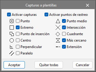
To snap entities or elements from the previously imported DXF, DWG or PDF file, you need to activate the third tool, "Template object snaps (F3)". In the pop-up window, you can tick the "Activate object snaps" box and the "Activate object snap tracking" box, as well as the references that will remain active. These are as follows:
- Activate object snaps
- Point, Edge, Insertion point, Centre, Perpendicular, Parallel
- Activate object snap tracking
- Midpoint, Intersection, Quadrant, Nearest, Extension
The F3 key can be pressed as a shortcut to enable or disable all template object snaps.
Template transformation

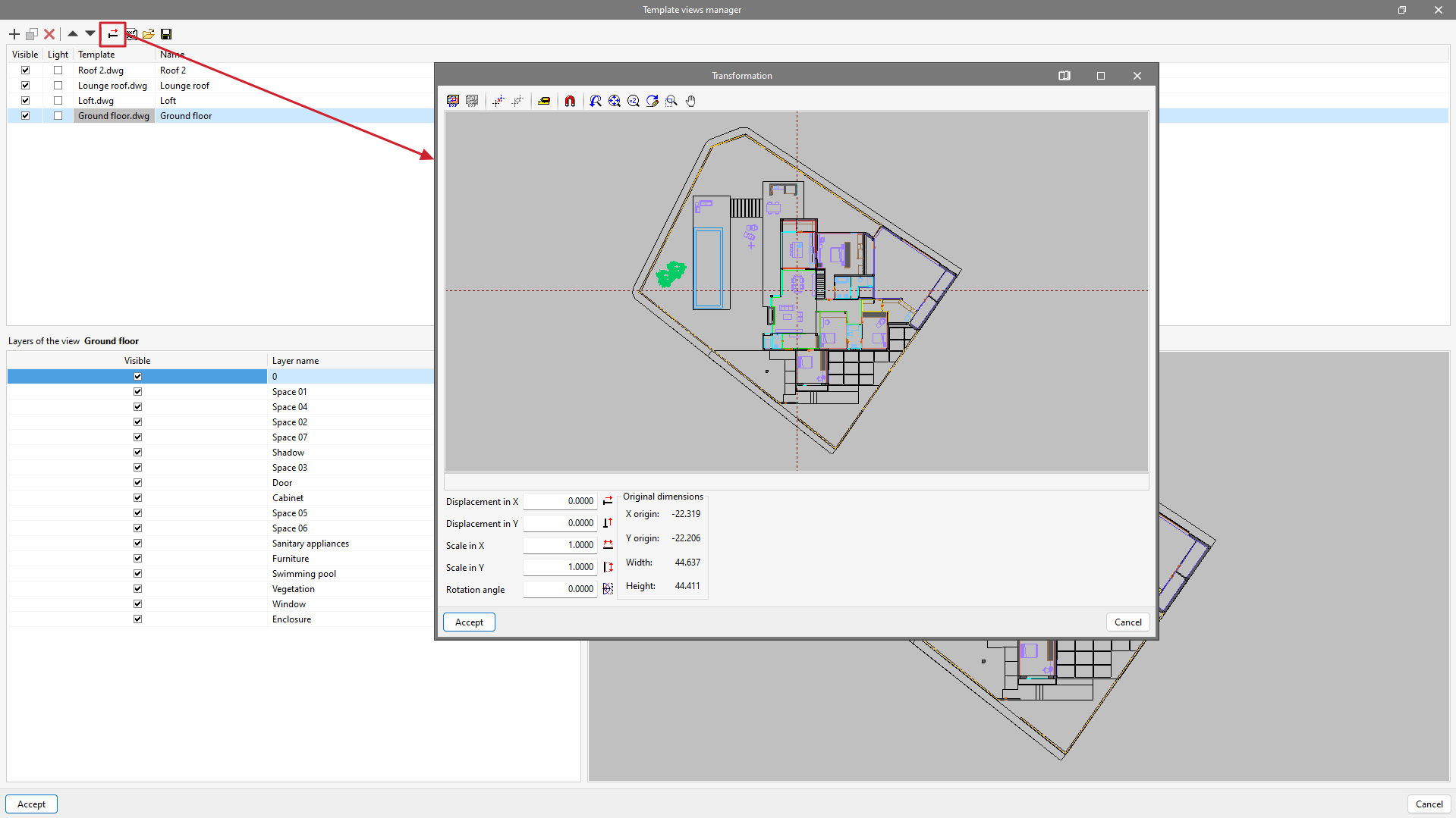
In "Template views manager", clicking on the tool with the red arrow will open a pop-up window called "Transformation", from which users can select the visible area of the template, apply a shift, rotate and/or change the scale, among others.
At the top of the window, we find a series of tools divided into groups:
- The first group allows users to "Select the visible area of the template" or restore the original area.
- The second group allows users to "Change the origin of the coordinates of a template" or reset it to the initial position.
- The third group, "Adjust the scale of a template", allows users to select two points on the template to create a segment with a known distance to adjust the scale of the template.
- The last group allows users to manage the visibility of the drawing view.
At the bottom of the window, we can enter numeric "Displacement" and "Scale" parameters on the "X" and "Y" axes or apply a "Rotation angle".
| More information: |
|---|
| The template transformation tool is very useful when different templates have to be imported from a single file. The drawings of a building are often grouped in a single file instead of being separated (per floor) in separate files. From the "Template views manager" window, the file containing the construction drawings must be added to the list and incorporated as many times as there are floors in the building. Once the floors have been correctly renamed, each template can be transformed by selecting the visible area for each floor and changing the coordinate origin to a common (or easily identifiable) element in all of them. Lift shafts, staircases, columns, etc. are recommended as a reference. |
Tools for adding elements
This panel, located in the top-right corner, provides tools to help add elements to the model.

The following options are available:
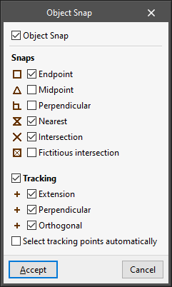
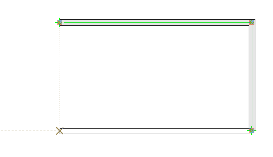
- Object snap (F2)
Activate object snaps previously entered in the program to snap or track them when entering new elements in the model.- Object snap (optional)
The object snap system can be configured to suit the needs of each situation:- Snaps (optional)
Directly snap the following points of the elements already entered in the program:- End point (optional)
- Midpoint (optional)
- Perpendicular (optional)
- Nearest (optional)
- Intersection (optional)
- Fictitious intersection (optional)
- Tracking (optional)
Generate and use the following tracking from the elements already entered in the program:- Extension (optional)
- Perpendicular (optional)
- Orthogonal (optional)
- Select tracking points automatically (optional)
If this option is activated, the program selects nearby track points automatically. If it is deactivated, the cursor must be moved for a few seconds over the points to be tracked.
- Snaps (optional)
- Object snap (optional)
| Note: |
|---|
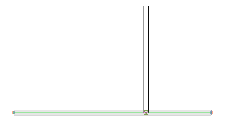
| Object snaps will be shown as different symbols next to the mouse cursor when hovering over the elements of the model. This informs the user about the type of object snap that is available at any given moment. |
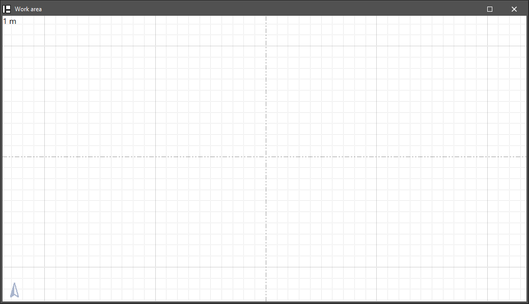
- Draw grid (F7)
Draw a modular help grid on the screen.
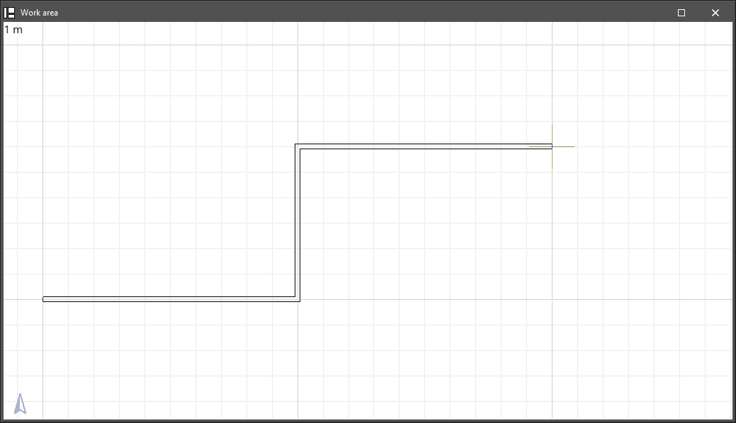
- Snap to grid (F9)
Snap to grid points when inserting elements into the model.
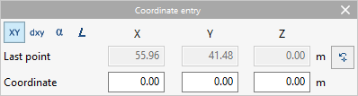
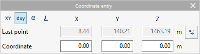
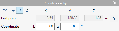
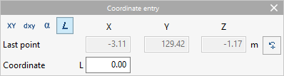
- Coordinate entry
Enter elements into the model by defining the position of their points by numerical coordinates.- Coordinate selection
The first row of options allows users to select the coordinates to be used:- Absolute coordinates
- Relative coordinates
- Polar coordinates
- Polar coordinates (Length)
- Last point
This section shows the absolute coordinates of the last point entered:- "X", "Y", "Z"
- Coordinate
This section shows different numerical fields in which the coordinates of the new point to be entered are entered. After typing in the numerical values, pressing the "Enter" key will enter the point of the element in the model. The available fields depend on the selected coordinates:- "X", "Y", "Z" (in "Absolute coordinates")
Allows users to directly type in the absolute coordinates "X", "Y" and "Z" of the new point. - "X", "Y", "Z" (in "Relative coordinates")
Allows users to enter the "X", "Y" and "Z" coordinates of the new point relative to the coordinates of the last point entered. - "L", "α" (in "Polar coordinates")
Allows the "L" length to be entered in the direction given by the "α" angle between the new point and the last point entered. - "L" (in "Polar coordinates (Length)")
Allows users to enter the "L" length between the new point and the last point entered in the direction defined by the cursor on the screen.
- "X", "Y", "Z" (in "Absolute coordinates")
- Coordinate selection
- Allows for dimensions to be defined upon entering each element
If this option is activated, when a new point is inserted in the model, a panel opens next to it, allowing for dimensions to be defined for its position. The following values can be selected and dimensioned:- Distance
- Length
- Absolute XY displacement
- Relative XY displacement
- Absolute length and exit angle
- Relative length and exit angle
- Absolute exit angle
- Relative exit angle
- Allows for dimensions to be defined upon entering each element
If this option is activated, when inserting a new point in the model, a panel opens next to it, allowing users to dimension it in order to define its position. Values can be selected and dimensioned in the following options, which are activated depending on whether a previous element is snapped or not when inserting the points in the model:- Distance
Distance from the new point to the nearby reference point indicated. - Length
Length of the element between the new point and the original point snapped. - Absolute XY displacement
X and Y displacements of the new point relative to the original point, in absolute coordinates. - Relative XY displacement
X and Y displacements of the new point with respect to the original point, in coordinates relative to the previous element where the first point is snapped. - Absolute length and exit angle
Length of the element between the new point and the original point, and exit angle with respect to the global axes. - Relative length and exit angle
Length of the element between the new point and the original point, and exit angle with respect to the direction of the previous element where the first point is snapped. - Absolute exit angle
Exit angle with respect to the global axes. - Relative exit angle
Exit angle with respect to the direction of the previous element where the first point is snapped.
- Distance

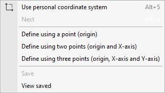
- Personal coordinate system
- Use personal coordinate system (Alt + 5)
Switch between using personal coordinate systems or the default coordinate system. - Next
Select the next defined personal coordinate system, if it has been previously saved. - Define using a point (origin)
Define a personal coordinate system by entering its origin. The direction of the "x" and "y" axes is calculated automatically. - Define using two points (origin and x-axis)
Define a personal coordinate system by entering two points: the coordinate origin and a second point indicating the direction of the x-axis. The direction of the y-axis is calculated automatically. - Define using three points (origin, x-axis and y-axis)
Define a personal coordinate system by entering three points: the coordinate origin, a second point indicating the direction of the x-axis and a third point defining the direction of the y-axis. - Save
Save the personal coordinate system by entering a "Reference" for it. - View saved
Consult the stored personal coordinate systems, edit their references and delete them.
- Use personal coordinate system (Alt + 5)
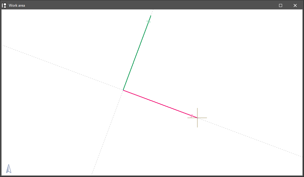
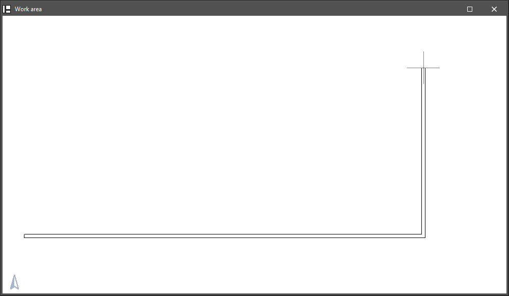
- Orthogonality (Ctrl + O)
If this option is activated, the position of the elements is forced when they are entered into the orthogonal directions of the active coordinate system.
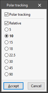
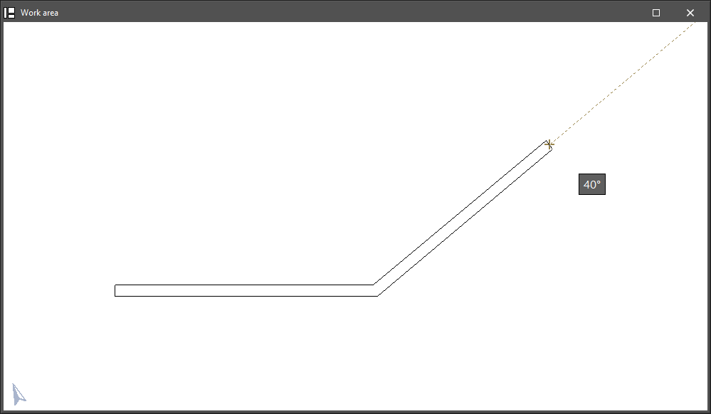
- Polar tracking
Force the lines of the tracking activated by the "Object snap" option to the directions given by the angles selected in this panel.- Polar tracking (optional)
Polar tracking can be activated. - Relative (optional)
If this option is activated, the selected angles shall be measured with respect to the direction given by the last points entered in the model. If deactivated, the selected angles shall be measured with respect to the coordinate system in use. - Angle selection
Select the angular increments between the different tracking lines:- 5
- 10
- 15
- 18
- 22.5
- 30
- 45
- 90
- Polar tracking (optional)
- Repeat the last selection
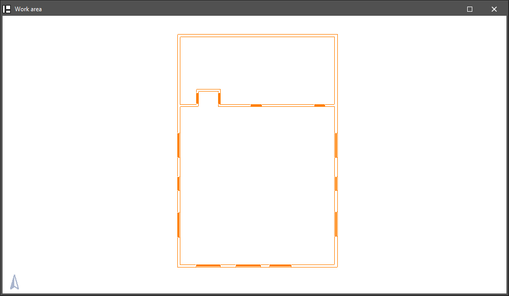
By pressing this option, the program selects the elements that were selected when using the last option, highlighting them in orange.
- Show information texts
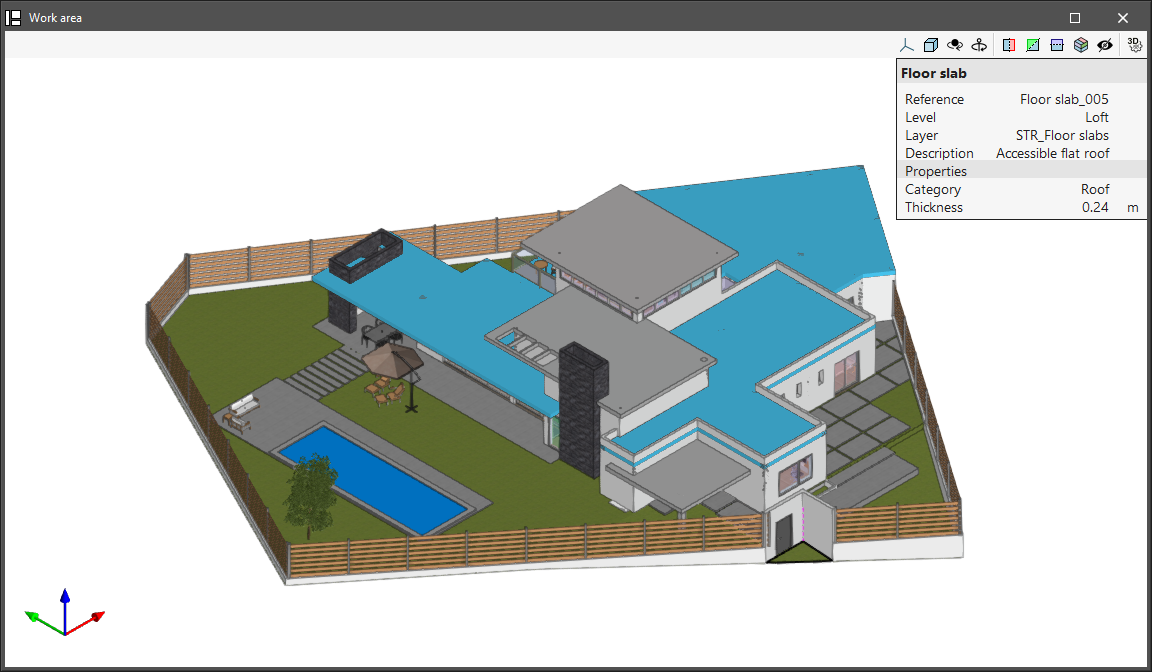
If this option is activated, the program allows users to consult the information of each element in a specific panel that appears when hovering the mouse cursor over them.
- Configuration
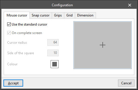
With this option, the appearance of different graphic elements that appear on the screen can be configured: - “Mouse cursor” tab
Allows users to modify the appearance of the mouse cursor:- Use the standard cursor (optional)
- On complete screen (optional)
- Cursor radius
- Side of the square
- Colour
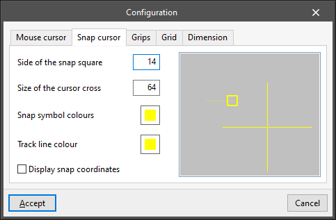
- “Snap cursor” tab
Modify the appearance of the snap cursor, which is displayed when nearby object snaps are detected:- Side of the snap square
- Size of the cursor cross
- Snap colour symbols
- Track line colour
- Display snap coordinates (optional)
- “Grips” tab
Modify the appearance of grips or insertion points of elements in the model:- Side of the square
- Border colour
- Fill colour
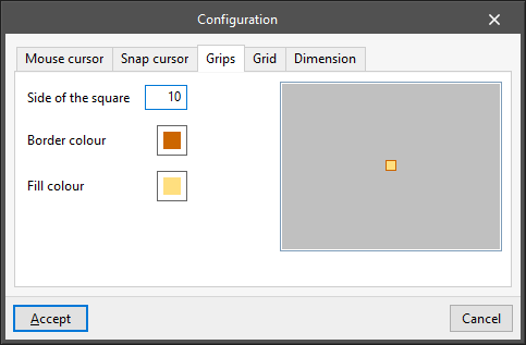
- “Grid” tab
Modify the appearance of the grid:- Draw grid (optional)
- Colour
- Intensity (%)
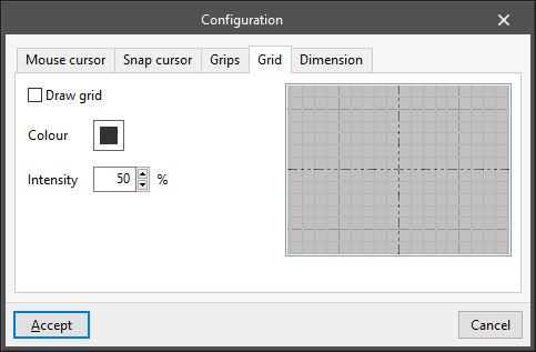
- “Dimension” tab
Modify the appearance of dimension lines:- Draw dimensions (optional)
- Length (colour selection)
- Distance to the closest extremity (colour selection)
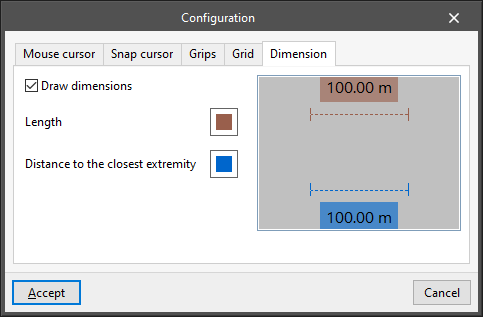
Dockable window system
The dockable window system lets users customise their workspace to suit their needs.
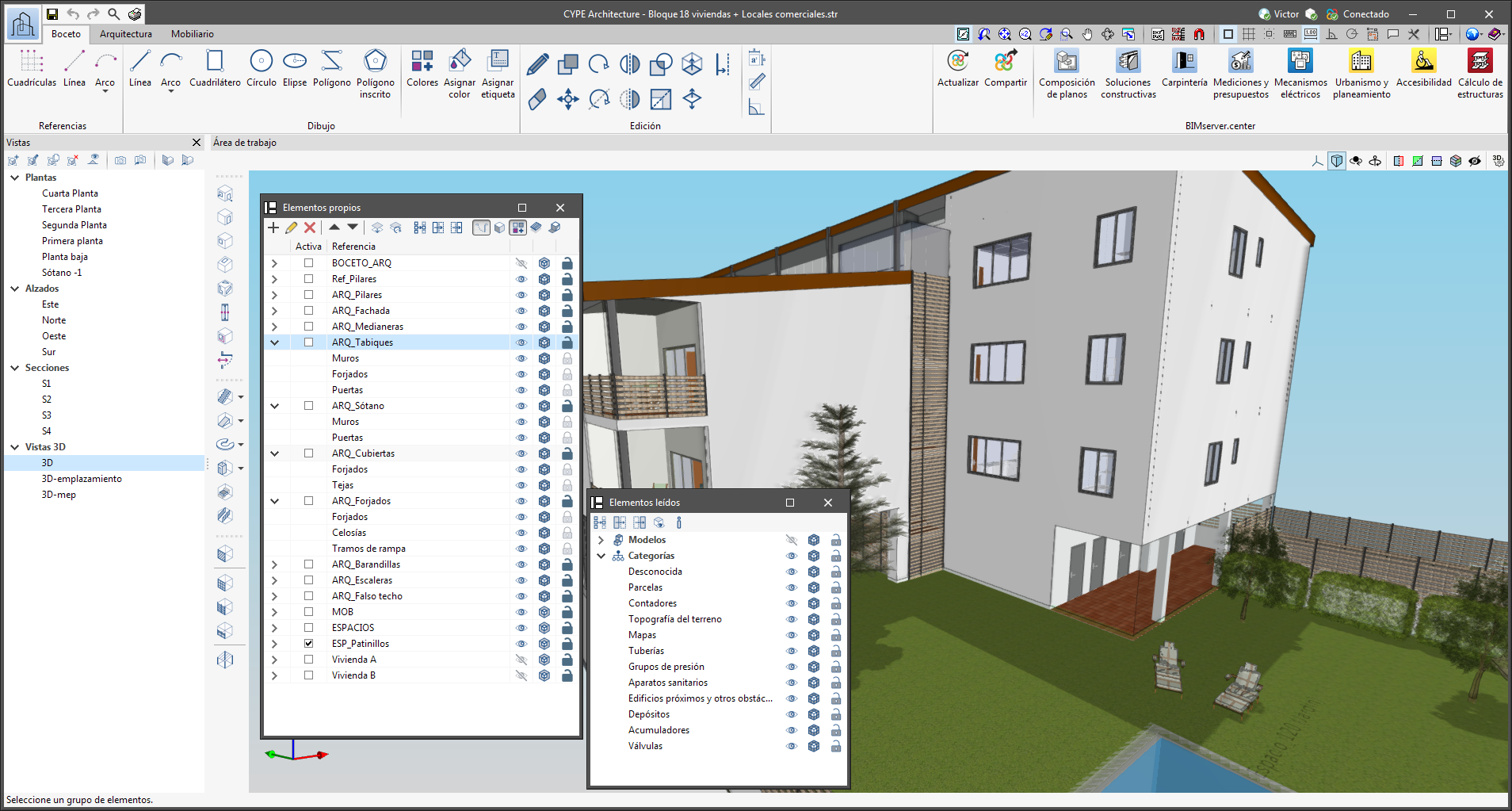
Dockable windows can be moved and resized. They can float, be docked within the main app window, or be dragged out of it and even moved to another monitor.
- Move windows
A docked window can be moved by clicking on the title bar at the top of the window and dragging it.
When dragging a dockable window, several visual aids are displayed to make its relocation easier. Next to the cursor, a text box appears containing the title of the dockable window being moved. Whenever the cursor approaches the edge of another window, a box appears showing a preview of the space it would occupy.
A window can be left as a floating window without docking it to another window, and it is also possible to dock windows within a floating window. Holding down the CTRL key can prevent a floating window from being docked while it is being moved.
- Group windows
Several windows in the same space can be grouped by dragging one window to the top left-hand corner or to the bottom left-hand corner of another window. When this is carried out, tabs will appear at the bottom or top of the group, allowing users to alternate between the grouped windows. If the tabs are at the bottom, the title of the group of windows corresponds to the active window. On the other hand, if the tabs are at the top, they will be used as the title.
- Show/Hide windows
The icon to close the window can be found in the top right-hand corner of each dockable window.
To manage the display of the dockable windows in the user interface, a "Window" button ( ) has been added to the app environment, next to the "General settings" button (icons on the top right-hand side of the program). By clicking on it, a drop-down menu appears with the available dockable windows, and users are able to change their status. In addition, there is the "Reset window layout" option, which allows users to restore the default workspace.
In some cases, such as the "Work area" in apps with a 3D environment, the window cannot be hidden. In these cases, the icon for closing the window is not displayed, and in the "Window" menu, the "Work area" will be locked.
 ) has been added to the app environment, next to the "General settings" button (icons on the top right-hand side of the program). By clicking on it, a drop-down menu appears with the available dockable windows, and users are able to change their status. In addition, there is the "Reset window layout" option, which allows users to restore the default workspace.
- Collapse windows
When several dockable windows are arranged vertically, an icon is displayed next to the close icon, which allows each window to be expanded or collapsed. When the window is collapsed, it will return to its previous size.
The window layout and display settings are saved when closing the app.
Please note that not all the floating windows in an app can be dockable windows. In order to tell them apart, the  icon has been added to the title bar of windows that are dockable.
The floating window environment also includes the "Bill of Quantities" tab in all programs that have this tab.
General configuration options
The general configuration options are accessible via the "Configuration" button in the top right-hand corner of the interface.

Clicking on this button displays a menu with different general configuration tools. The options displayed depend on the program being used.
The following options are available:
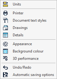
Units
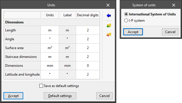
This is used to configure the project's system of units. The quantities available in the table depend on the program being used.
- "Units" column
Selects the unit of measurement for each of the magnitudes. - "Label" column
Displays the label identifying the selected unit. - "Decimal digits" column
Modifies the number of decimal places used to measure each magnitude in the selected unit. - Import one of the predefined systems of units
Using this option available on the right-hand side, the units from one of the following predefined systems can be imported automatically:- International System of Units
Imports the units from the International System of units. - I-P System
Imports the units from the I-P (Inch-Pound) or imperial system.
- International System of Units
- Import/Export
Using these options, the defined system of units can be imported and exported to files on disk.
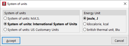
In some programs, such as CYPECAD, the panel only allows you to select the "System of units" from the following options:
- The "M.K.S." system (metre, kilogram and second)
- The "International System of Units"
- The "Imperial units" system.
If you choose the International System, you can select whether the "Energy unit" is the joule, the kilocalorie or the British thermal unit. The program will then use the derived units: for example, it will express power in watts if you have chosen joules as the energy unit, or in kilocalories per hour if you have chosen kilocalories as the energy unit.
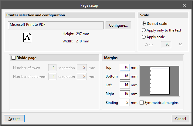
Printer
Opens the "Page setup" window with the following options:
- Printer selection and configuration
Selects and configures the printer used for printing documents. - Scale
Adjusts the scale when printing documents:- Do not scale
- Apply only to the text
- Scale (%)
- Apply scale
- Scale (%)
- Divide page (optional)
Prints the page divided into rows and columns:- Number of rows and separation between rows
- Number of columns and separation between columns
- Margins
Modifies the margins on the printed page:- Top
- Bottom
- Left
- Right
- Binding
- Symmetrical margins (optional)
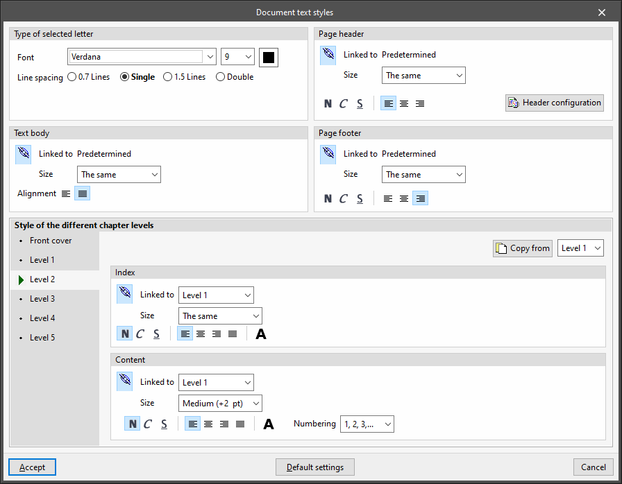
Document text styles
Configures the styles of the documents. The characteristics of each style can be linked to those of the default font style, indicating whether it has the same or different font "Size", or unlinked, to define them independently.
- Type of selected letter
Sets the default font:- Font style
- Font size
- Colour
- Line spacing (0.7 lines / Single / 1.5 lines / Double)
- Page header
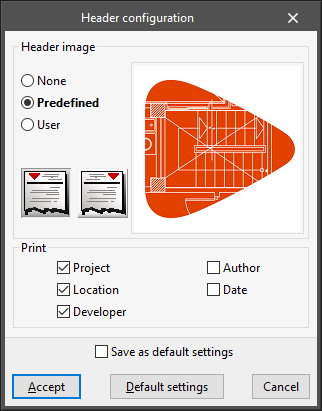
Sets the style used in the document's page header. The format can be set to bold, italic or underlined, and the alignment can be changed. The following editing panel can also be accessed:- Header configuration
Sets the image and the data to be printed in the page header:- Header image
- None / Predefined / User defined
- Image on the left / Image on the right
- Header image
- Header configuration
- Text body
Configures the style used in the text body of documents. The alignment can be changed. - Page footer
Sets the style used in the footer of documents. The formatting can be set to bold, italic or underlined, and the alignment can be changed. - Style of the different chapter levels
Configures the style used in the different levels of chapters, both in their "Table of contents" and in their "Contents". Using the "Copy from" option, the style defined in each level is copied to any other level. The style of one level can also be linked to the style defined in another level. Also, using the "Numbering" option, users can select the heading numbering system. The available levels are as follows:- Front cover
- Level 1
- Level 2
- Level 3
- Level 4
- Level 5
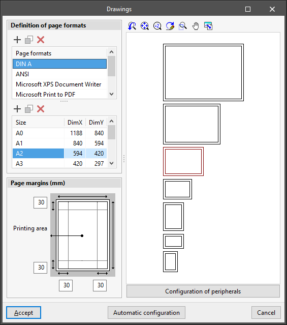
Drawings
Configures the formats and peripherals for printing drawings.
- Definition of page formats
Configures the page formats and sizes available when printing drawings. Users can edit, add, copy or delete entries in two tables:- Format table
The first table defines the series of available formats. - Table of page sizes
When selecting a format in the first table, the second table defines the page sizes available in the format and their dimensions:
- Format table
- Page margins
Configures the print margins of drawings (top, bottom, left and right) around the "Print area". - Format viewer
In this display area, the selected format series and the selected page size are shown schematically. - Configuration of peripherals
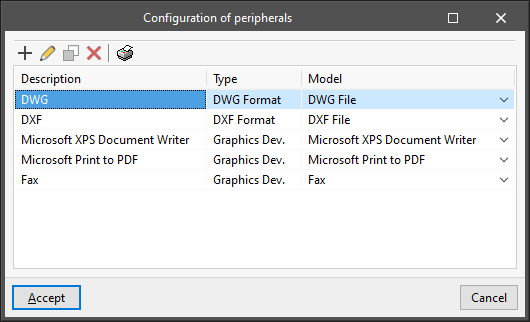
Accesses to the printing peripherals configuration table. By default, the program includes the "DWG" and "DXF" peripherals, which allow printing on these files, together with the graphic devices registered in the operating system control panel. The configuration options available when editing each peripheral vary according to its type:- Configure drawing program
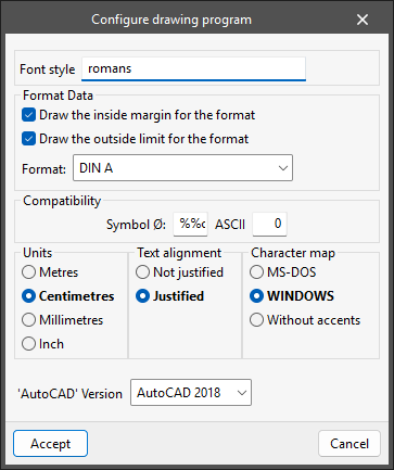
This panel appears when editing the "DXF" and "DWG" peripherals and allows users to configure the printing on these files:- Font style
- Format Data
- Draw the inside margin for the format (optional)
- Draw the outside limit for the format (optional)
- Format
- Compatibility
- Symbol Ø
- ASCII
- Unit display (Metres / Centimetres / Millimetres / Inch)
- Text alignment (Not justified / Justified)
- Character map (MS-DOS / Windows / Without accents)
- 'AutoCAD' version (AutoCAD 2004 / AutoCAD 2000 / AutoCAD R14 / AutoCAD R13 / AutoCAD R11)
- Configure printer
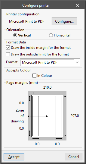
This panel appears when configuring a printer type peripheral:- Printer configuration
- Orientation (Vertical / Horizontal)
- Format Data
- Draw the inside margin for the format (optional)
- Draw the outside limit for the format (optional)
- Format
- Accepts Colour
- In Colour (optional)
- Page margins
- Configure drawing program
Details
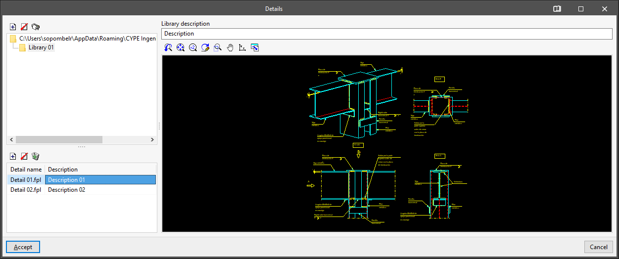
This tool is used to store user detail libraries to be included in the drawings later on.
Creating libraries
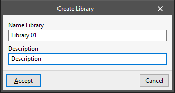
First, new libraries are created to hold the new details. These libraries can be organised in directories and subdirectories. When creating a new detail library, the program requires the following data:
- "Create Library" window
- Name of the library
- Library description
Creating details
Details are created by importing DXF, DWG or image files. After selecting the library where the detail is to be imported, the program will allow users to import a file with the detail.
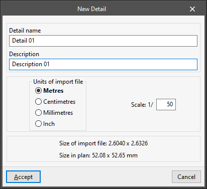
When importing a DXF or DWG, a dialogue box opens in which users must indicate the name to be assigned to the detail, a description, the drawing units with which the file is being created and the scale it is to be transferred to:
- "New Detail" window (DXF and DWG files)
- Detail name
- Detail description
- Units of import file (Metres / Centimetres / Millimetres / Inches)
- Scale (1/n)
With this data, the program calculates the final dimensions that the detail will have in the plan. Thus, the "Size of import file" and the "Size in plan" are displayed.
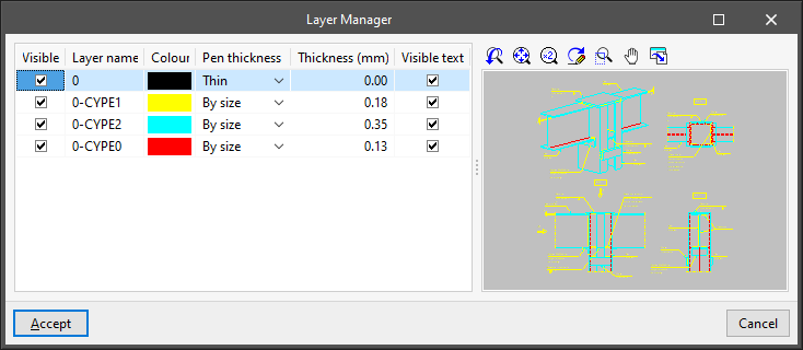
In the next window of the import process, users can choose which layers should be visible, whether texts should be activated, the pen thickness and the layer name:
- "Layer management" window
- Visible, Layer name, Colour, Pen thickness, Thickness (mm), Visible text
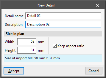
When importing an image file, a dialogue box opens where the name to be assigned to the detail, a description and the data required to define its size in plan must be indicated:
- "New detail" (image files) window
- Detail name
- Detail description
- Size in plan
- Width (mm)
- Height (mm)
- Keep aspect ratio (optional)
| Note: |
|---|
| To add user details to the drawings, use the "Details" option available in the drawing printing process of each program, go to "File", then to "Job drawings", and finally to "New". Then select the "Add user detail" option. Also, default details from the CYPE library can be included if they are available in the program by selecting the "Add" option. This is the case of the CYPECAD construction details library. |
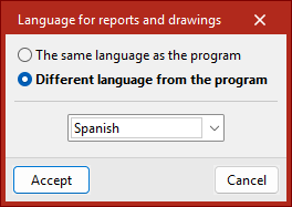
Language for reports and drawings
Permite seleccionar un idioma distinto al del programa para obtener los listados y planos.
- The same language as the program
Uses the default language in which the program was installed. - Different language from the program
Selects a different language from those available in the drop-down menu.
The "Language for reports and drawings" option is also accessible from the "File" menu, under "Reports" or "Drawings".
| Best practice: |
|---|
| It should be noted that the references of certain elements in the job, such as the names of groups and floors, will be displayed in the language in which they were entered. The same applies to certain general settings of the program, such as the names of the "Floor plans" or the chapters of the "Customised reports". The names of the operations are not translated when generating a report in CYPE Connect or StruBIM Steel; they are a reference defined by the user or the default reference. |
Appearance
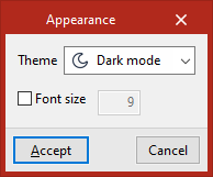
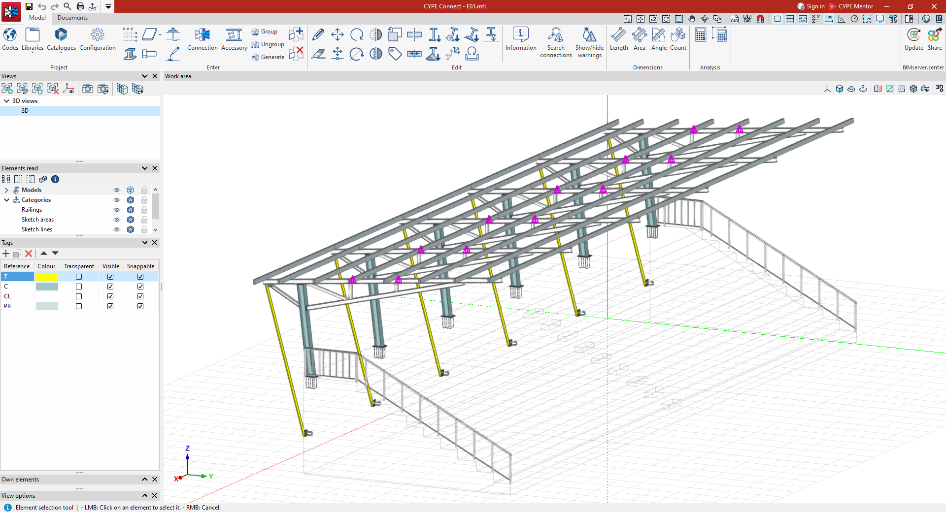
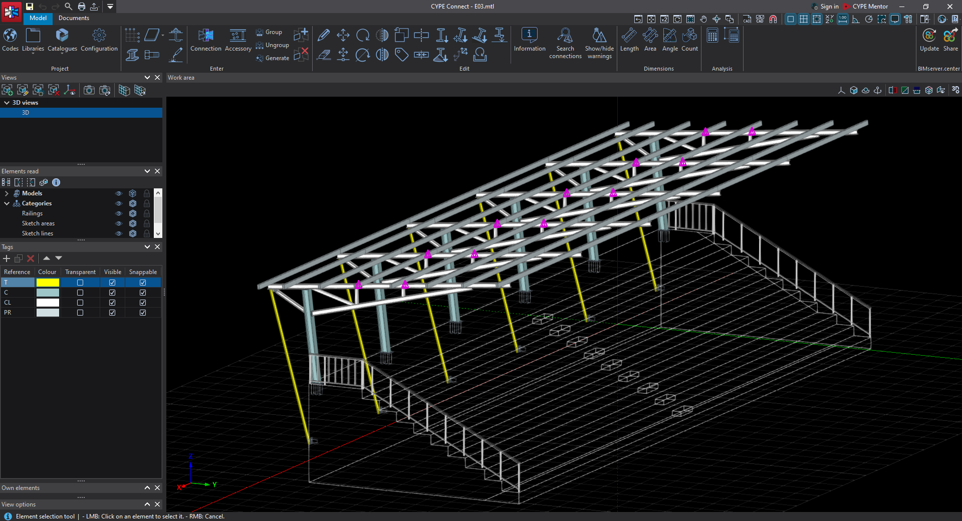
The "Appearance" option allows you to switch between "Light mode" and "Dark mode".
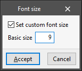
You can also check the relevant box to change the "Font size" used in the app.
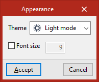
- Light mode features an interface with a light background—white or very light grey—and dark text. It creates a brighter feel and is generally more readable in brightly lit environments.
- Dark mode features an interface with a dark background—black or dark grey—and light text. It reduces screen brightness and can make it easier to work for long periods, helping to reduce eye strain, particularly in dimly lit environments.
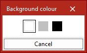
This option can be found in the "Settings" panel on the initial interface that appears when you open each program, as well as in the "Settings" menu located at the top right of the programs’ main interface. The "Background colour" of the workspace can also be changed using the corresponding option in this same window or menu.
To apply the changes, you must close and reopen the program. Please note that the appearance settings are shared across all programs; therefore, any changes made in one will automatically apply to the others when they are launched.
3D performance
Sets the parameters related to 3D performance.
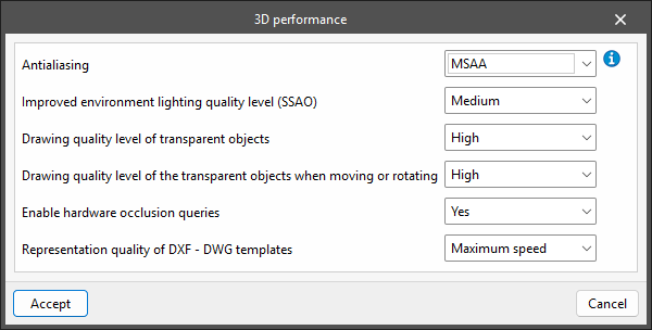
- Antialiasing
Antialiasing, also known as edge smoothing, is a process that improves the appearance of an image by reducing the level of pixelation at the edges of geometric primitives. Depending on the technique used, the hardware available on the PC and the configuration of the video card driver, the graphics performance may be affected. The available configuration options are:- No
No edge smoothing technique is applied. The graphics speed is as fast as possible. The edges of the geometric primitives in the image are clearly pixelated when they are not aligned with the horizontal and vertical directions of the screen. - FXAA
This is a software technique that can be applied with any video card. The image quality is good and the impact on graphics speed is minimal. This is the recommended setting for work areas. - MSAA
This technique can only be applied with video cards that support it. The image quality is good, and the edge definition of geometric primitives is excellent at 4 samples and above. However, depending on the PC hardware, the graphics speed may be affected. This is the recommended value for display areas. - FXAA+MSAA
Combines the two previous techniques and produces an image of excellent quality.
- No
- Improved environment lighting quality level (SSAO)
- Low / Medium / High / Maximum
- Drawing quality level of transparent objects
- Low / High
- Drawing quality level of the transparent objects when moving or rotating
- Low / High
- Enable hardware occlusion queries
- Yes / No
- Representation quality of DXF - DWG templates
- Maximum speed / Maximum precision
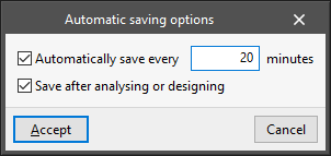
Options in the "Help" menu
The "Help" menu option is located in the upper right-hand corner of the interface.

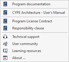
Clicking on this option displays a menu with the following options:
- Program documentation
- Program License contract
- Responsabilidad clause
- Technical support
- User community
- Learning resources
- About
This menu also includes links to manuals, calculation reports, practical examples and other documents available for each program.
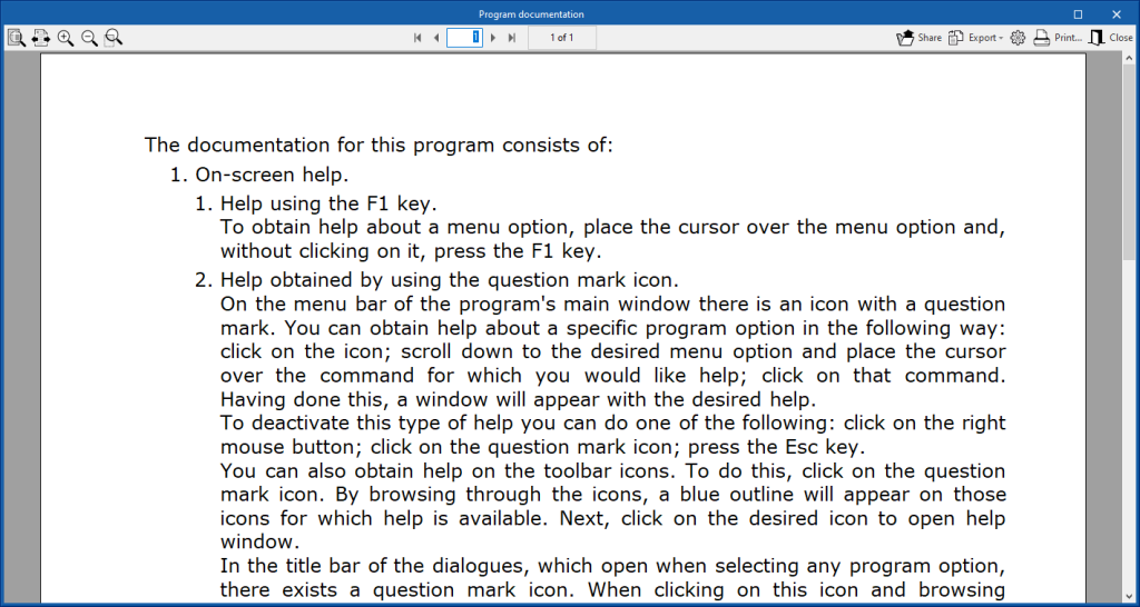
Program documents
Provides access to explanatory text on the program documents and their location, both within its interface and through external resources.
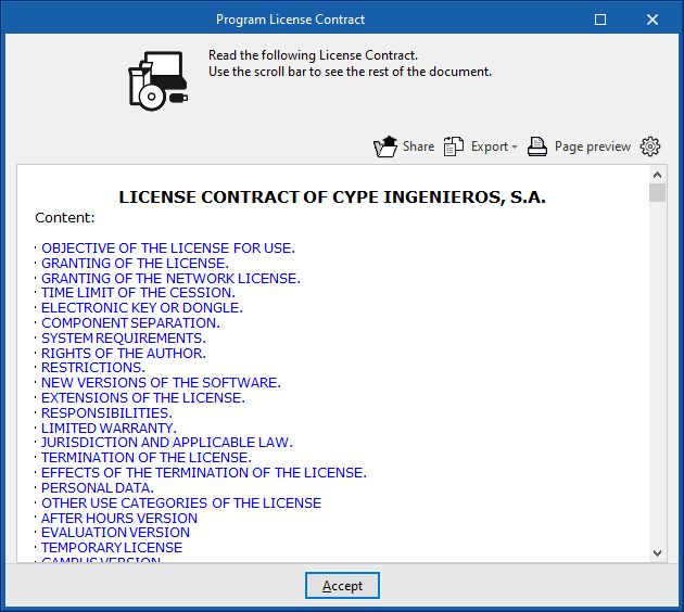
Program License Contract
Allows users to consult the license contract for the programs. This document is displayed and must be accepted when the program is installed.
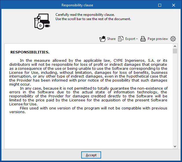
Responsibility Clause
Allows users to check the responsibility clause. This document is displayed and must be accepted when the program is installed.
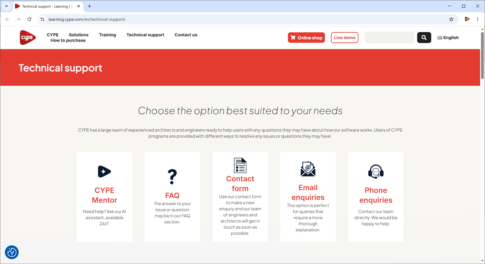
Technical support
Link to the website with Frequently Asked Questions (FAQs), contact forms, and contact details for CYPE Technical Support, including email and telephone support.
User community
Link to the website providing access to the CYPE software user communities and related discussion forums, including BIMserver.center and Sólo Arquitectura.
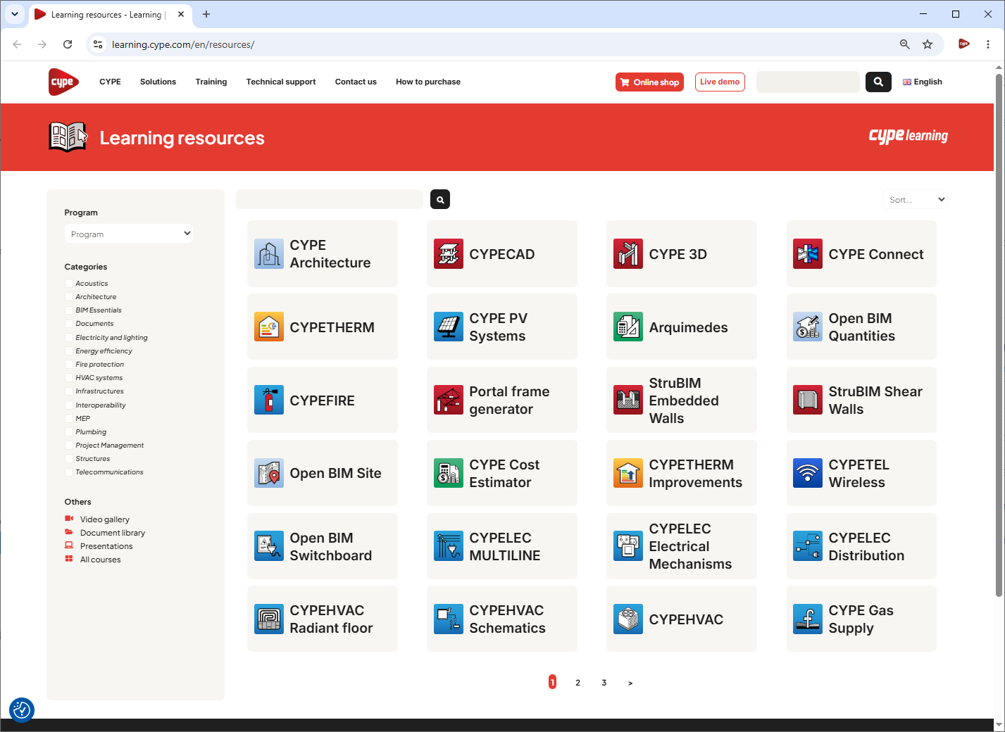
Learning resources
Link to the website which provides access to the learning resources for each of CYPE's programs, including their detailed information pages, audiovisual resources such as videos, tutorials and seminars, as well as the library of related documents and the frequently asked questions.
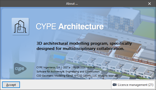
About
Allows users to view information about the program, the version and the licence number currently in use. By clicking on "Licence management", it is also possible to read licences on the network, as well as to use, activate or manage the electronic licence, and to view the permissions it contains and those required by the program.
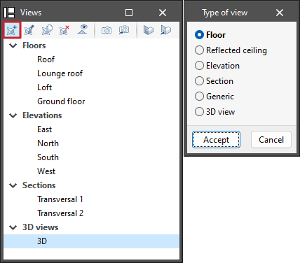
Managing views
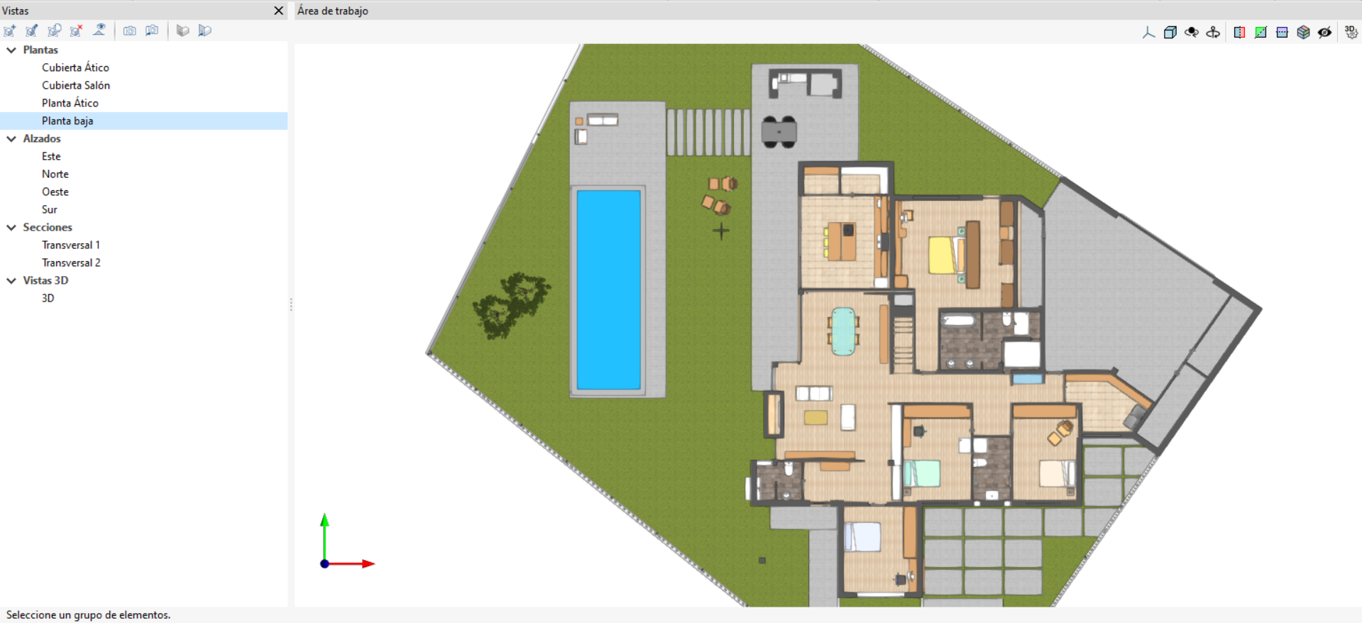
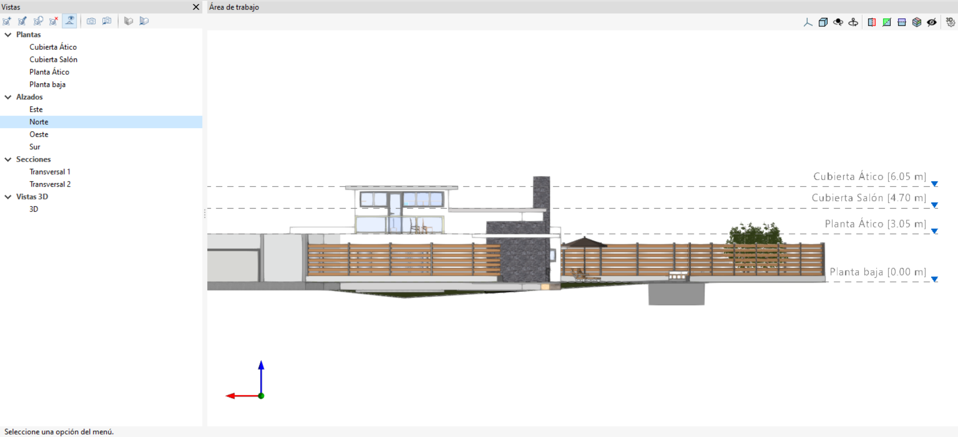
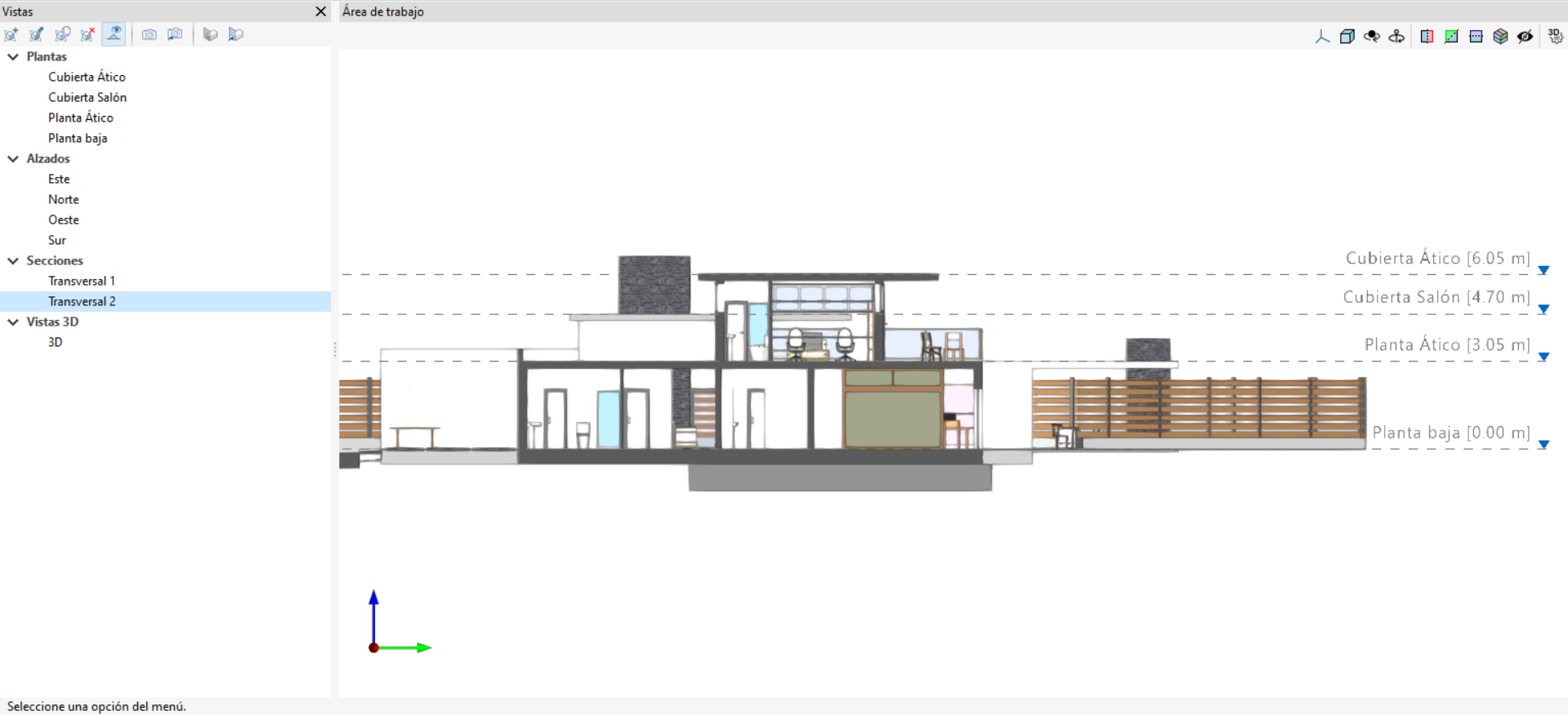
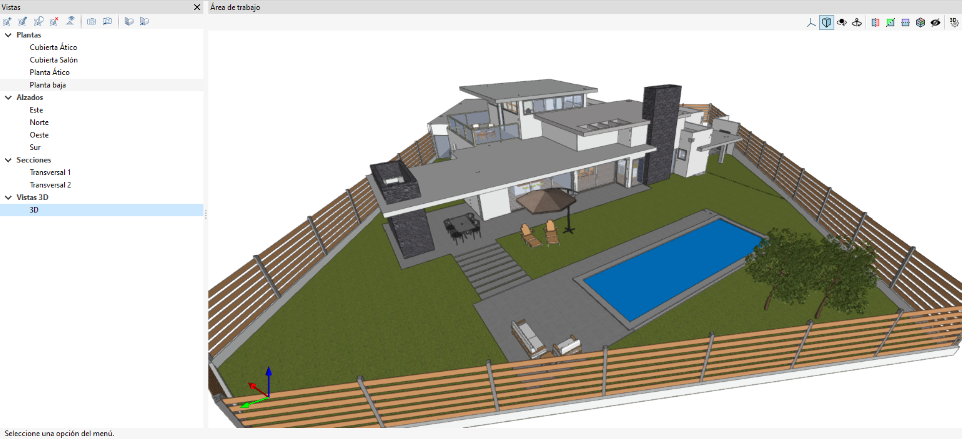
Programs with the "Views" section can create different views to make navigation and the architectural modelling process easier. You can create the following types: floor, reflected ceiling, elevation, section, generic and 3D view.
The following options are also available in the top toolbar:
- Create
Create a new 2D or 3D view of the model. - Edit
Modify the properties of the current view. - Duplicate
Copy the current view. - Delete
Delete the current view. - Show references
Display references to other views in the active view. - Save the start scene
Set the current position of the view as the start scene. - Go to start scene
Set the current view to the starting scene. - Define
Specify the workplane associated with the current view. The work plane serves as the basis for the entry of the model components. - Go to the workplane
Align the current view with the position of the work plane.
"General configuration" tab
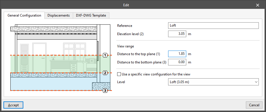
When you "Edit" each view, you can adjust the following settings in the "General settings" tab:
- Reference
View reference. - Use a specific display configuration for the view (optional)
When this option is enabled, the text "View" will appear in the "Read elements" menu, and its settings will apply only to the selected view.
If this option remains disabled, the text "View" will not be displayed, and the "Read elements" settings for the entire project will be visible and can be adjusted.
The following fields are displayed in the floor plans:
- Elevation level
The elevation where the view is located, measured relative to the general horizontal XY plane. - Level
Select the level associated with the view. This ensures that this level is automatically applied to any elements added to that view, provided that automatic elevation detection is not used.
| Note: |
|---|
| Floors form an internal data structure within the building model, whilst floor plans are simply partial representations of the model on screen. |
In the 2D views, the following section appears:
- View range
These values specify the distance to each of the planes from the view origin.
All view types, except for the 3D view, are associated with a region bounded by two planes, which determines which elements will be displayed within it.
For example, plan views will show the elements bounded and cropped by two planes situated at the specified "Distance to the top plane" and "Distance to the bottom plane", measured from the "Level dimension".
In elevation views, section views and generic views, the rear plane is the one perpendicular to the viewing direction in the positive direction. The front plane is the same, but in the negative direction.
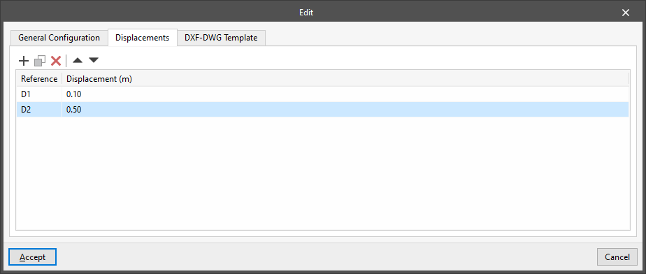
"Displacements" tab
In this tab, you can create and manage displacements associated with the view, which can be loaded and used when entering elements into the view using the relevant option.
These displacements are applied to the level or position dimension of the view plane.
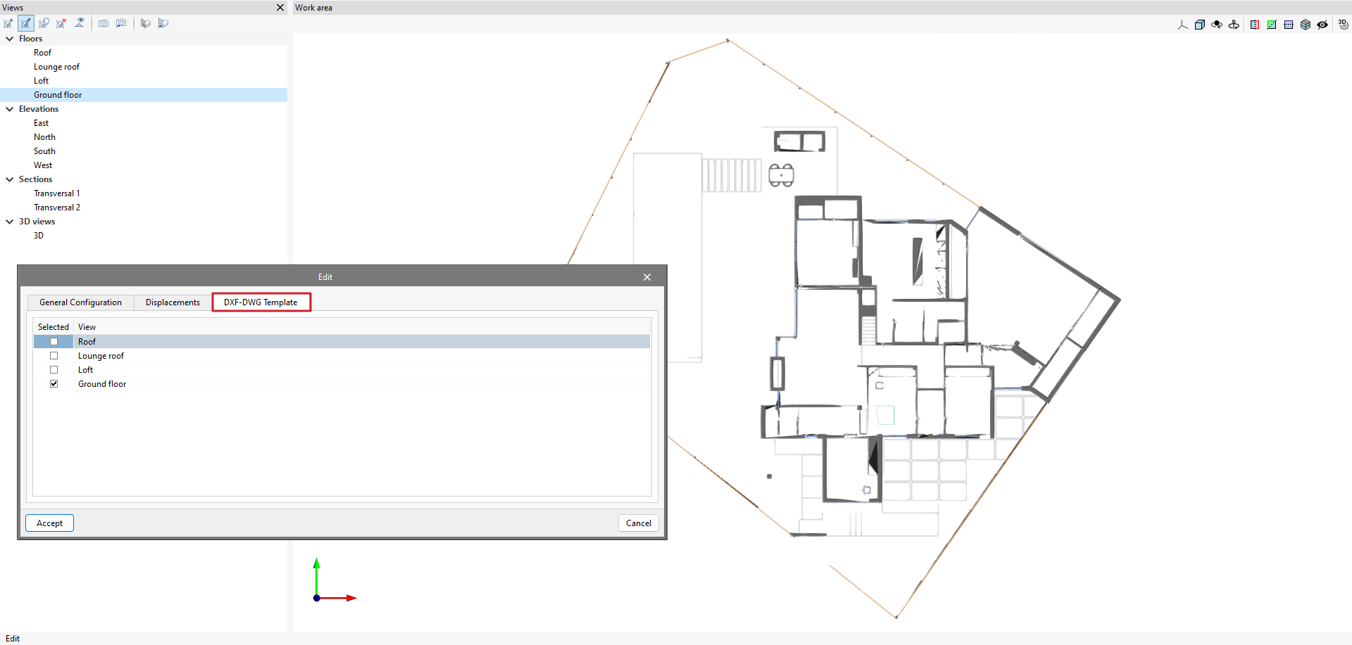
"DXF-DWG Template" tab
From the "Views" section, whilst creating or editing a view, you can manage the visibility of templates on the "DXF-DWF Template" tab.
This tab displays a report of all the templates imported into the project.
Ticking the box will display the template on the assigned floor plan.
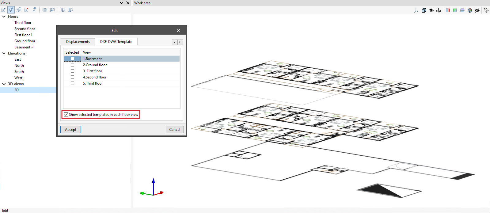
Furthermore, in 3D views, you can enable the "Show selected templates in each floor view" option.
When this option is ticked, the templates visible in each floor plan view will be displayed in the 3D view and at the corresponding dimension.
| More information: |
|---|
| The following link explains how to import DXF, DWG, PDF and JPG drawings into the project. |
Level management
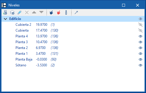
The "Levels" section makes it easier to associate elements of the model to various views, such as building plans or other reference planes. There is a drop-down list of buildings and levels defined in the model.
The toolbar can add new buildings and levels to the model. Next to each level, the elevation is shown along with the number of associated model components in brackets. Their visibility can be activated or deactivated in the work area.
With the "Assign elements to a level" option, components of the model can be selected from the work area and associated with the level selected in the list. The "Unassign elements to a level" option allows the reverse operation to be carried out.
From the "Information on the level of an element" option, users can inspect an object from the workspace and obtain its current level.
Finally, the "Automatic assignment" option associates the components of the model to the defined levels automatically. To do this, it analyses the element’s geometry and identifies the level immediately below it.
Managing elements read
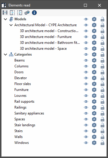
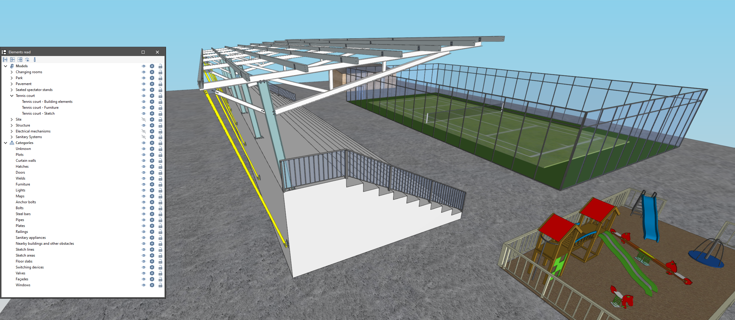
The management of the elements from the digital model of the building, obtained from the associated BIM project, is carried out from the "Elements read" menu located on the left sidebar in the app.
The elements read are structured in the form of a tree according to two types of classification:
- By "Models": users can inspect each contribution linked to the job and, within this, each associated 3D model.
- By "Categories": users can group the "Elements read" into families according to their characteristics.
Three buttons are displayed next to each component of the tree:
- Visible
Enable or disable the visibility of the elements. - Visualisation mode
Toggle between normal, transparent and wired display modes. - Snap
Enable or disable object snaps of the elements.
| Note: |
|---|
| Please note that the settings applied within the organisation using "Models" are prioritised over those specified using "Categories". |
The following actions can be carried out via the toolbar in the top left-hand corner:
- Isolate selection
Isolate elements of the 3D model. By selecting the elements of the 3D model to be isolated and clicking the right mouse button, the rest of the elements of the model will disappear. - Hide
Hide the selected elements. By selecting the elements of the 3D model to be hidden and right-clicking on them, they will disappear. - Show all
Show all hidden elements. - Appearance
Choose between normal drawing and monochrome drawing. - BIM information
Display a panel with the attributes associated with the selected component.
Settings by "View"
If the "Use a specific display setting for this view" option has been enabled in the active view, the text "View" will appear in the "Read elements" menu, and the settings defined will apply only to the selected view.
Otherwise, the general settings for the entire job will be displayed and applied.
Own element management
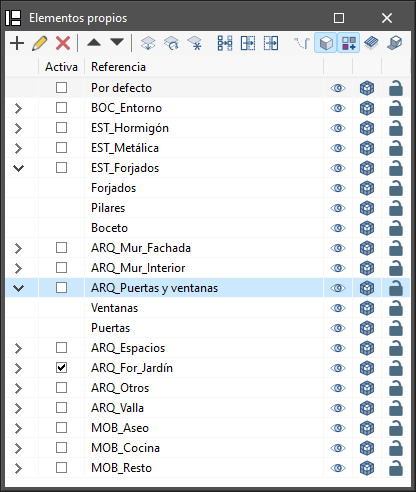
In this section, the elements of the job opened by the program the user is working with are organised in layers that can be created, deleted, edited, sorted, shown or hidden according to their preferences. Within each layer, the elements can be displayed in grouped categories, which can be expanded or collapsed by clicking on the arrows on the left.
Depending on the program being used, the following options and controls appear next to each component of the tree:
- Visible
Enable or disable the visibility of the elements. - Visualisation mode
Choose between normal, transparent and wired display modes. - Snap
Activate or deactivate object snaps of the elements.
In the top toolbar, several options for managing layers can be found:
- Add
Create a new layer. - Edit
Edit the selected layer reference. - Delete
Delete the selected layer reference. - Move selected element up/down the list
Move the selected layer one place up or down in the list. - Assign layer (Ctrl + A)
This makes it easier to change the element from one layer to another. The program allows users to select the layer where the element is to be assigned. - Update layers
Regenerate the display of all layers and makes them visible. - Isolate layer
Isolates the active layer, hiding the other layers available in the project. - Isolate selection (Ctrl + I)
Select several elements to remain visible; those not selected will be hidden. - Hide elements (Ctrl + H)
Control the visibility of each element. - Show elements (Ctrl + U)
Undo the "Isolate selection" and "Hide elements" actions mentioned above.
Options for entering elements in the "Work area"
The option bar for entering elements is located at the top left of the "Work area" window and appears when entering or editing an element in the model. This bar has the following options, which depend on the active view and the element(s) being entered or edited:

- Force elevation (optional)
Defines the position of the new element in the model.- If this option is active:
- If a component of the model is snapped, its position will be projected onto the work plane of the view selected in the drop-down menu, where the new element will be inserted, adjusted with the "Displacement" indicated on the right.
- If no component is snapped, the new element will be inserted at the cursor position and on the working plane of the view selected in the drop-down menu, adjusted with the "Displacement" indicated on the right.
- If this option is left deactivated:
- If a component of the model is snapped, the new element will be inserted at the exact position of that component, even if it is outside the working plane of the selected view.
- If no component is snapped in, the new element will be inserted at the cursor position and on the work plane of the selected view in the "Views" panel.
- If this option is active:
- Select views (drop-down window)
This drop-down menu is used to select one of the views created in the "Views" panel to support the operation of the "Force elevation" option:- In 2D views such as elevations, sections or plans, the selector is locked to the view selected in the "Views" panel; this means that no other view can be selected.
- In 3D views, any of the views created in the "Views" panel can be selected.
| Nota: |
|---|
| The "Views" panel is located by default on the left-hand side of the program's general interface and allows users to create and maintain 2D and 3D views of the model. Each of these views has an associated "work plane", which can be defined using the top options of the "Views" panel mentioned above. |
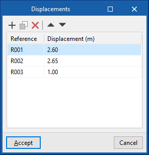
- Displacement (optional)
Used to enter a displacement value, either positive or negative, which will be applied to the position of the working plane of the view selected in the drop-down menu above. The option to the right of this field is used to save and load displacements for each view, indicating their reference and value.
- Points
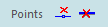
This section is activated when inserting points in the workspace to define the geometry of a new element and has the following options:- Erase the last entered point
- Erase all entered points
- Angle
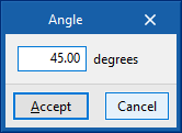
Used to indicate the insertion angle of the new element in the "Work area" with respect to the display on the screen by means of the following options:- 0º
- 90º
- 180º
- 270º
- Editable angle

Visibility monitoring tools to support the modelling
In the top right corner of the 3D viewing area is a toolbar that is used to control the visibility of the model during the modelling process.
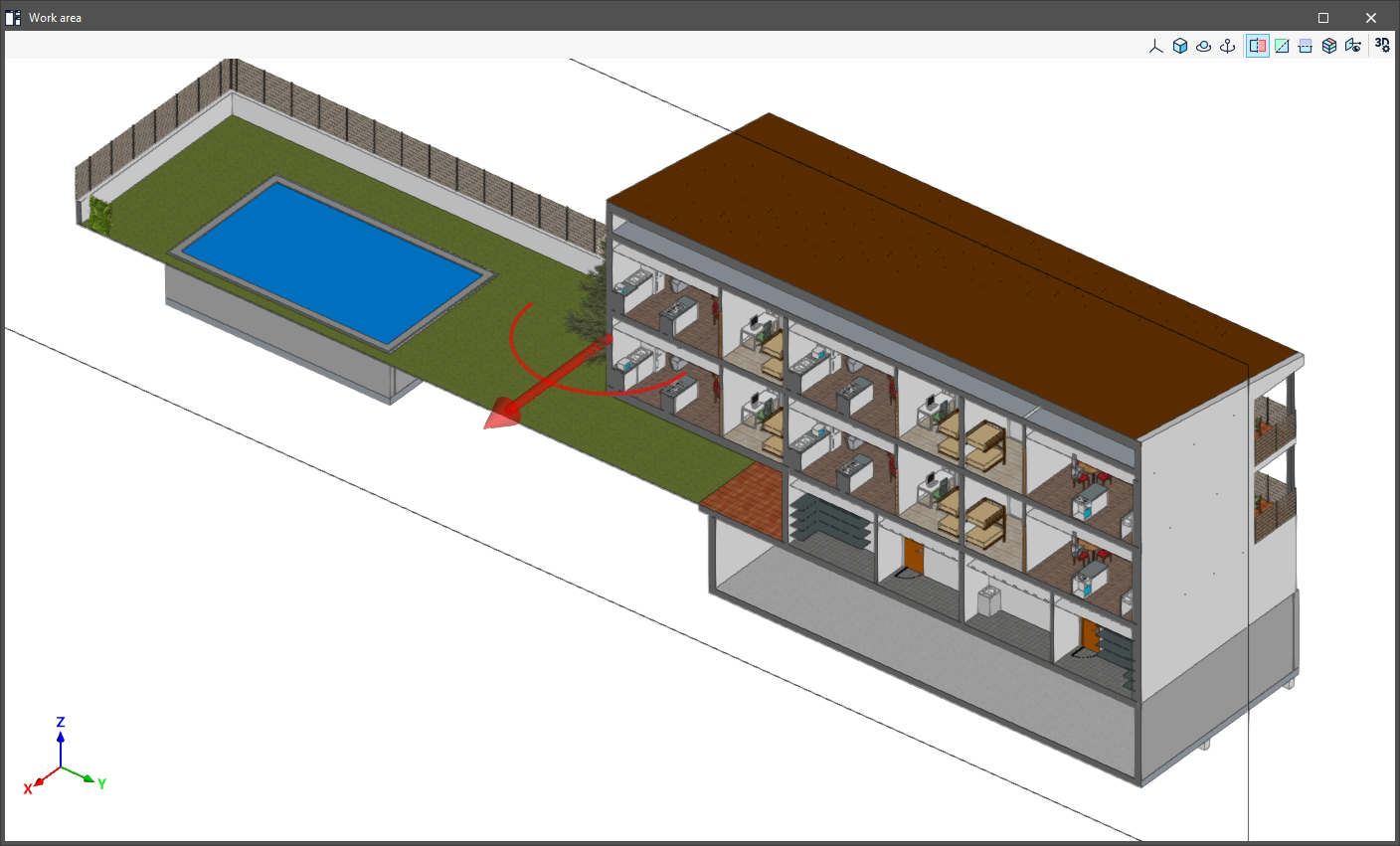
This bar offers various options to make it easier to manage and visualise the project. Some of the options are shown in the following image.
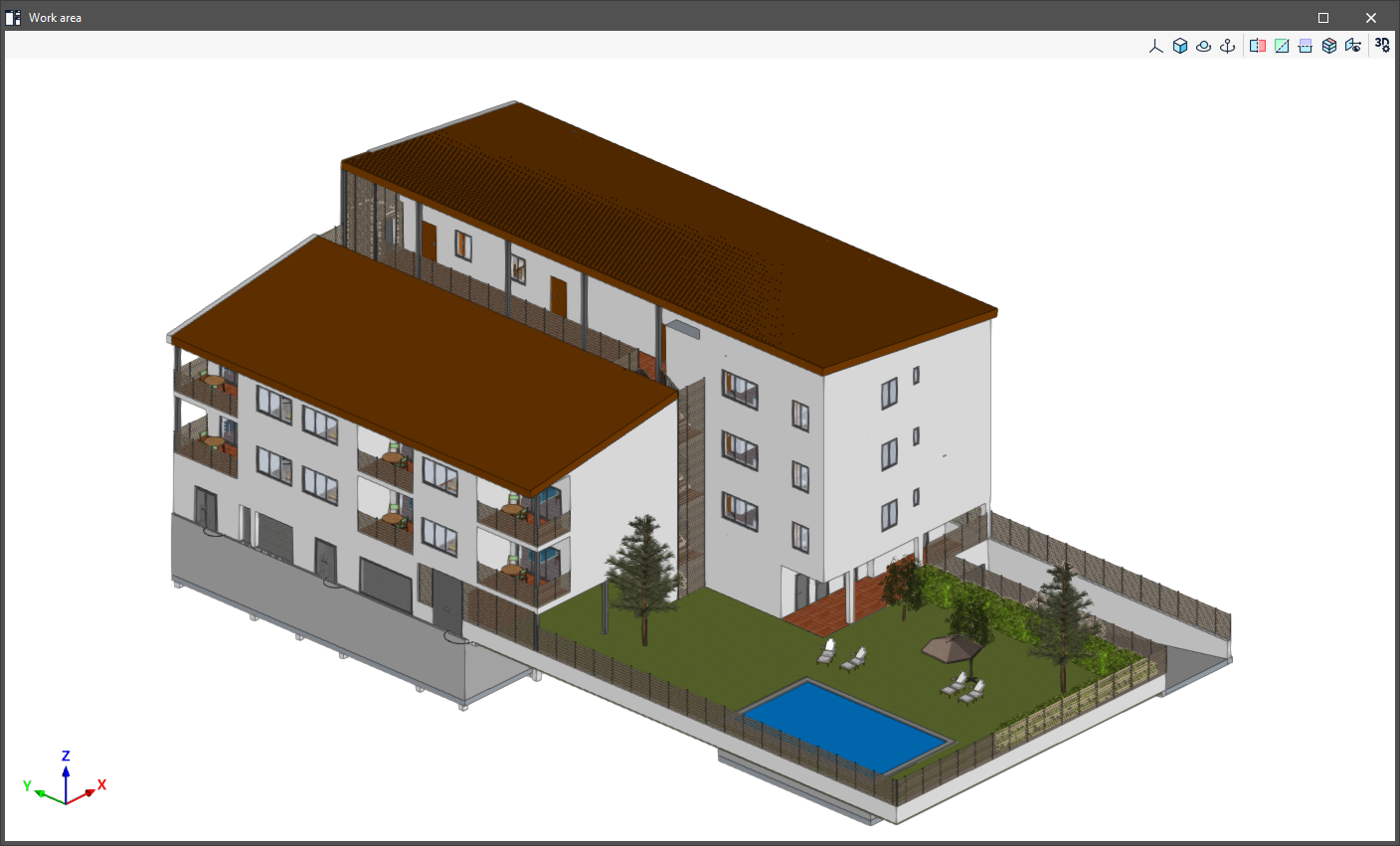

The first section covers the options for controlling the display modes of the model:
- Projection
Open a window that allows users to select predefined projections, such as top view, front view, isometric view, orthogonal view, etc. - Projection type
Modify the type of projection from axonometric to conic and vice versa. - Rotation around a point
Activate or deactivate the rotation of the scene around a point of an object located under the cursor. - Rotation around the camera
Activate or deactivate the rotation of the scene around the vertical axis of the camera.
The following 5 options are used to create sections for viewing the BIM model from different perspectives and to create customised views.
- Section perpendicular to the global "X" axis
Define a section of the model perpendicular to the global "X" axis. - Section perpendicular to the global "Y" axis
Define a section of the model perpendicular to the global "Y" axis. - Section perpendicular to the global "Z" axis
Define a section of the model perpendicular to the global "Z" axis. - Clip volume
Define a display volume using 6 cutting planes that is formed from the geometric envelope of the scene content. - Show/Hide section planes
Manage the visibility of the lines and symbols of the sections created.- You can move and reposition each section plane by clicking and dragging the arrow icon that defines it.
- To rotate each section plane, click and drag the curved arc symbol next to the arrow.
- You can also flip the orientation of each section plane by double-clicking the arrow icon.
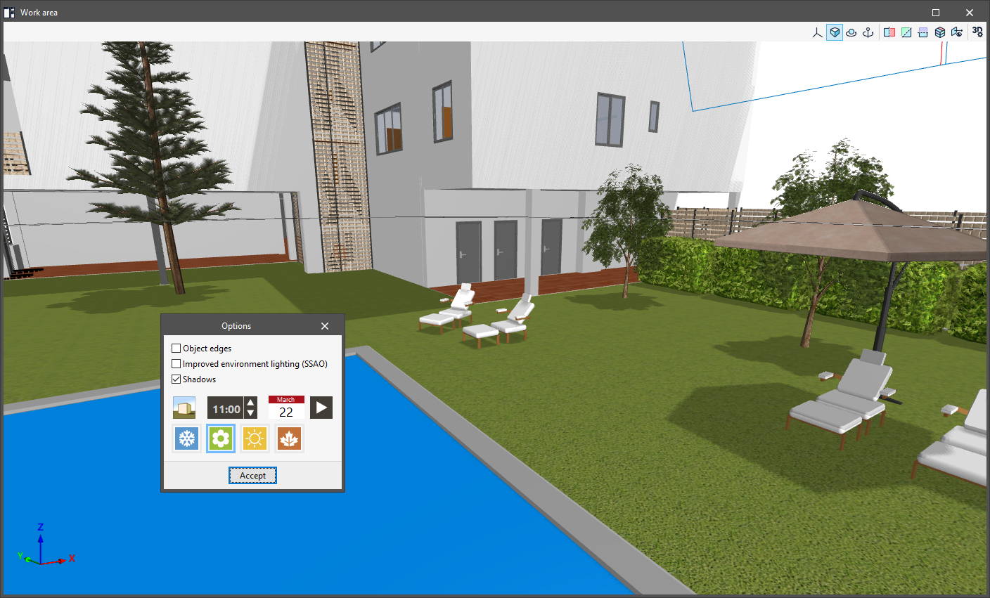
The last option opens the "Options" panel, which contains the following tools:
- Object edges (optional)
Enable or disable the display of object edges in the scene. - Enhanced ambient lighting (SSAO) (optional)
Enable or disable enhanced ambient lighting in the scene. - Shadows (optional)
If this option is enabled, the program simulates the sun's path across the site throughout the year, making it possible to assess the impact of surrounding shading cast by both the building itself and nearby buildings and other obstructions.- Display
Display the position of the sun on the selected day and at the selected time, as well as the path or positions of the sun throughout the year. - Time
Select the solar time. - Date
Select the date. - Animation
Display an animation of the shadows cast throughout the year at the selected time. Pressing this button again stops the animation. - Winter / Spring / Summer / Autumn
These options are shortcuts that can load the first day of each season directly.
- Display
Initial information. Table of contents
Please refer to the following general information to familiarise yourself with CYPE's software and start working with it:
- Access
- Basic installation
- Advanced installation
- Getting started
