Tools to assist with entering elements
This tool group is located on the top right-hand side of the interface and offers features to assist with entering elements into the model.

The following options are available:
- Object snap (F2)
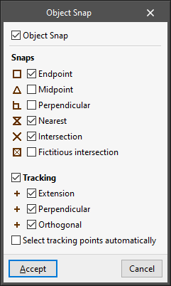
Allows users to activate object snaps previously entered in the program to snap or track them when entering new elements in the model.- Object snap (optional)
The object snap system can be configured to suit the needs of each situation:- Snaps (optional)
Allows users to directly snap the following points of the elements already entered in the program:- End point (optional);
- Midpoint (optional);
- Perpendicular (optional);
- Nearest (optional);
- Intersection (optional);
- Fictitious intersection (optional).
- Tracking (optional)
Allows users to generate and use the following tracking from the elements already entered in the program:- Extension (optional);
- Perpendicular (optional);
- Orthogonal (optional).
- Select tracking points automatically (optional)
If this option is activated, the program selects nearby track points automatically. If it is deactivated, the cursor must be moved for a few seconds over the points to be tracked.
- Snaps (optional)
- Object snap (optional)
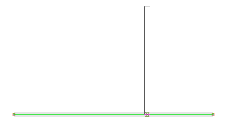
Note:
Object snaps will be shown as different symbols next to the mouse cursor when hovering over the elements of the model. This informs the user about the type of object snap that is available at any given moment.
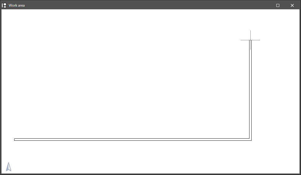
- Draw grid (F7)
Allows users to draw a modular help grid on the screen.
- Snap to grid (F9)
Allows users to snap to grid points when inserting elements into the model.
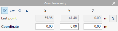
- Coordinate entry
Allows users to enter elements into the model by defining the position of their points by numerical coordinates.- Coordinate selection
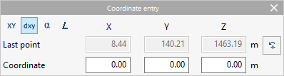
The first row of options allows users to select the coordinates to be used:- Absolute coordinates
- Relative coordinates
- Polar coordinates
- Polar coordinates (Length)
- Last point
This section shows the absolute coordinates of the last point entered:- "X", "Y", "Z"
- Coordinate
This section shows different numerical fields in which the coordinates of the new point to be entered are entered. After typing in the numerical values, pressing the "Enter" key will enter the point of the element in the model. The available fields depend on the selected coordinates:- "X", "Y", "Z" (in "Absolute coordinates")
Allows users to directly type in the absolute coordinates "X", "Y" and "Z" of the new point. - "X", "Y", "Z" (in "Relative coordinates")
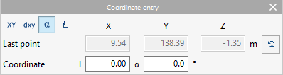
Allows users to enter the "X", "Y" and "Z" coordinates of the new point relative to the coordinates of the last point entered. - "L", "α" (in "Polar coordinates")
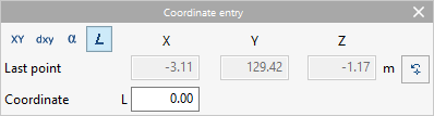
Allows the "L" length to be written in the direction given by the "α" angle between the new point and the last point entered. - "L" (in "Polar coordinates (Length)")
Allows users to enter the "L" length between the new point and the last point entered in the direction defined by the cursor on the screen.
- "X", "Y", "Z" (in "Absolute coordinates")
- Coordinate selection
- Allows for dimensions to be defined upon entering each element
If this option is activated, when a new point is inserted in the model, a panel opens next to it, allowing for dimensions to be defined for its position. The following values can be selected and dimensioned:- Distance
- Length
- Absolute XY displacemen
- Relative XY displacement
- Absolute length and exit angle
- Relative length and exit angle
- Absolute exit angle
- Relative exit angle
- Allows for dimensions to be defined upon entering each element
If this option is activated, when inserting a new point in the model, a panel opens next to it, allowing users to dimension it in order to define its position. Values can be selected and dimensioned in the following options, which are activated depending on whether a previous element is snapped or not when inserting the points in the model:- Distance
Distance from the new point to the nearby reference point indicated. - Length
Length of the element between the new point and the original point snapped. - Absolute XY displacement
X and Y displacements of the new point relative to the original point, in absolute coordinates. - Relative XY displacement
X and Y displacements of the new point with respect to the original point, in coordinates relative to the previous element where the first point is snapped. - Absolute length and exit angle
Length of the element between the new point and the original point, and exit angle with respect to the global axes. - Relative length and exit angle
Length of the element between the new point and the original point, and exit angle with respect to the direction of the previous element where the first point is snapped. - Absolute exit angle
Exit angle with respect to the global axes. - Relative exit angle
Exit angle with respect to the direction of the previous element where the first point is snapped.
- Distance

- Personal coordinate system
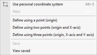
- Use personal coordinate system (Alt + 5)
Allows users to switch between using personal coordinate systems or the default coordinate system. - Next
Allows users to select the next defined personal coordinate system, if it has been previously saved. - Define using a point (origin)
Allows users to define a personal coordinate system by entering their origin. The direction of the "x" and "y" axes is calculated automatically. - Define using two points (origin and x-axis)
Allows users to define a personal coordinate system by entering two points: the coordinate origin and a second point indicating the direction of the x-axis. The direction of the y-axis is calculated automatically. - Define using three points (origin, x-axis and y-axis)
Allows users to define a personal coordinate system by entering three points: the coordinate origin, a second point indicating the direction of the x-axis and a third point defining the direction of the y-axis. - Save
Allows users to save the personal coordinate system by entering a "Reference" for it. - View saved
Allows users to consult the stored personal coordinate systems, edit their references and delete them.
- Use personal coordinate system (Alt + 5)
- Orthogonality (Ctrl + O)
If this option is activated, the position of the elements is forced when they are entered into the orthogonal directions of the active coordinate system.
Note:
It is also possible to maintain orthogonality by holding down the "Shift" key when inserting an element into the model.
- Polar tracking
Allows users to force the lines of the tracking activated by the "Object snap" option to the directions given by the angles selected in this panel.- Polar tracking (optional)
Allows polar tracking to be activated. - Relative (optional)
If this option is activated, the selected angles shall be measured with respect to the direction given by the last points entered in the model. If deactivated, the selected angles shall be measured with respect to the coordinate system in use. - Angle selection
Allows users to select the angular increments between the different tracking lines:- 5
- 10
- 15
- 18
- 22.5
- 30
- 45
- 90
- Polar tracking (optional)
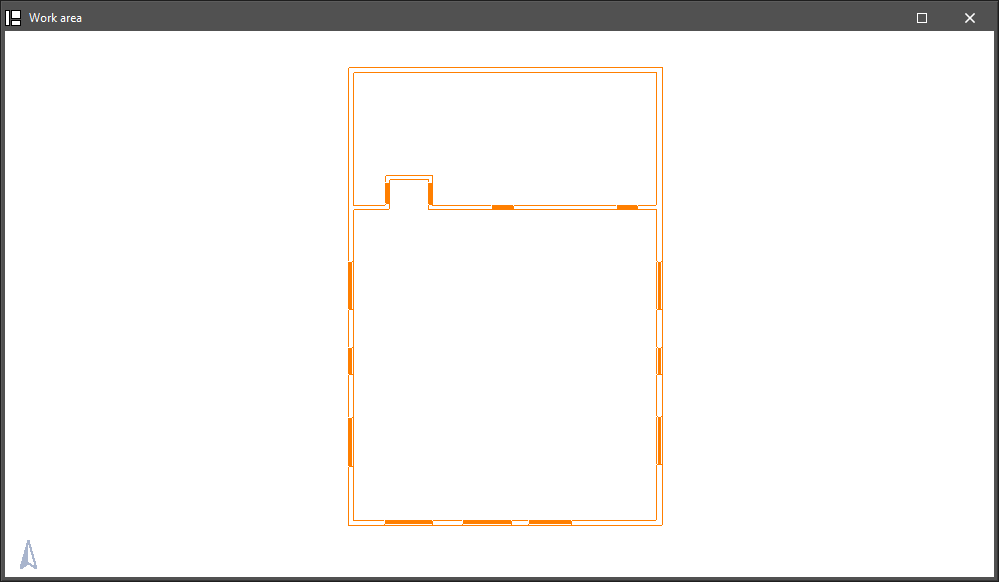
- Repeat the last selection
By pressing this option, the program selects the elements that were selected when using the last option, highlighting them in orange.
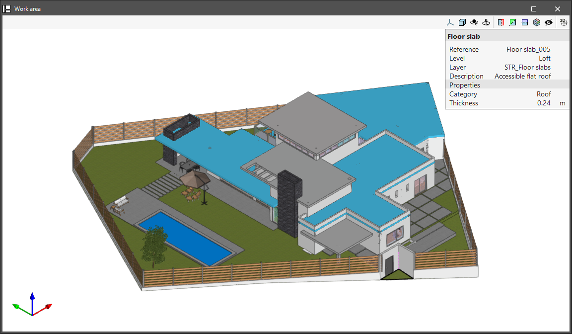
- Show information texts
If this option is activated, the program allows users to consult the information of each element in a specific panel that appears when hovering the mouse cursor over them.
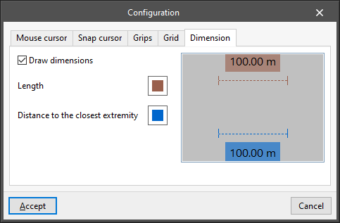
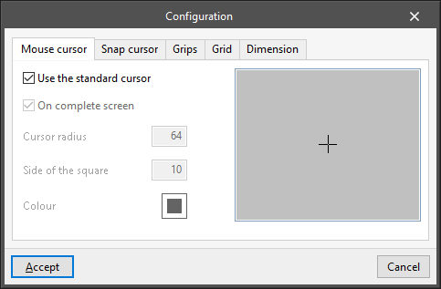
- Configuration
With this option, the appearance of different graphic elements that appear on the screen can be configured: - “Mouse cursor” tab
Allows users to modify the appearance of the mouse cursor:- Use the standard cursor (optional)
- On complete screen (optional)
- Cursor radius
- Side of the square
- Colour
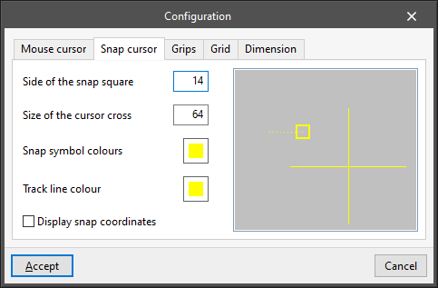
- “Snap cursor” tab
Allows users to modify the appearance of the snap cursor, which is displayed when nearby object snaps are detected:- Side of the snap square
- Size of the cursor cross
- Snap colour symbols
- Track line colour
- Display snap coordinates (optional)
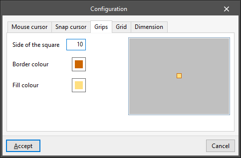
- “Grips” tab
Allows users to modify the appearance of grips or insertion points of elements in the model:- Side of the square
- Border colour
- Fill colour
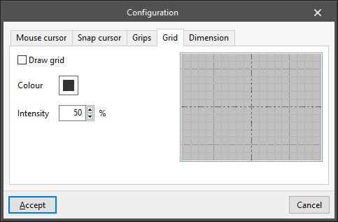
- “Grid” tab
Allows users to modify the appearance of the grid:- Draw grid (optional)
- Colour
- Intensity (%)
- “Dimension” tab
Allows users to modify the appearance of dimension lines:- Draw dimensions (optional)
- Length (colour selection)
- Distance to the closest extremity (colour selection)